ignition MAZDA 323 1992 Suplement Owner's Guide
[x] Cancel search | Manufacturer: MAZDA, Model Year: 1992, Model line: 323, Model: MAZDA 323 1992Pages: 279, PDF Size: 24.15 MB
Page 185 of 279

GI Reading Wiring Diagrams
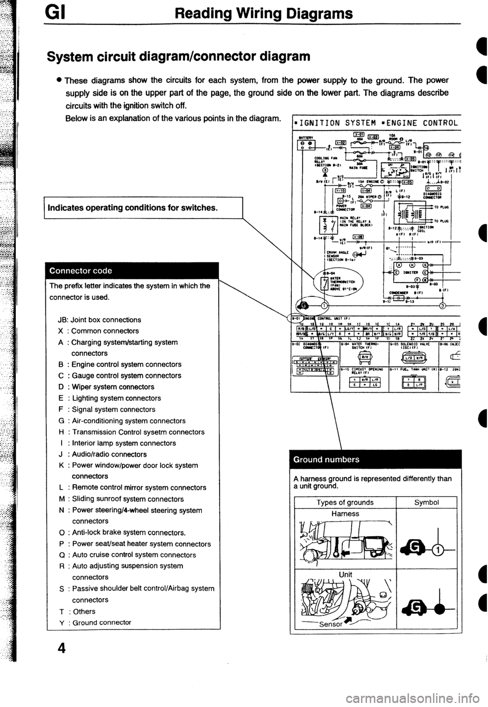
System circuit diagram/connector diagram
l These diagrams show the circuits for each system, from the power supply to the ground. The power
supply side is on the upper part of the page, the ground side on the lower part. The diagrams describe
circuits with the ignition switch off. Below is an explanation of the various points in the diagram.
I Indicates operating conditions for switches.
I
The prefix letter indicates the system in which the
:onnector is used.
JB: Joint box connections
X : Common connectors
A : Charging system/starting system
connectors
B : Engine control system connectors
C : Gauge control system connectors
D : Wiper system connectors
E : Lighting system connectors
F : Signal system connectors
G : Air-conditioning system connectors
l-l : Transmission Control sysetm connectors
I : Interior lamp system connectors
J : Audio/radio connectors
K : Power window/power door lock system
connectors
L : Remote control mirror system connectors
M : Sliding sunroof system connectors
N : Power steering/4-wheel steering system
connectors
0 : Anti-lock brake system connectors.
P : Power seat/seat heater system connectors
Q : Auto cruise control system connectors
R : Auto adjusting suspension system
connectors
S : Passive shoulder belt control/Airbag system
connectors
T : Others
Y : Ground connector
4
IGNITION SYSTEM mENGINE CONTROL
A harness ground is represented differently than
a unit ground.
Types of grounds
Harness
Unit Symbol
Page 190 of 279

-
Reading Wiring Diagrams GI
Symbol
Horn Meaning l Generates sound when current flows. Symbol Switch (1) Meaning l Allows or breaks current flow by
opening and closing circuits.
Speaker
ccl
Heater l Generates heat when current flows. Normally open (NO)
Switch (2)
I
Normally closed (NC)
Harness l Unconnected intersecting harness.
Speed sensor
+ Movement of magnet in speedometer
turns contact within sensor on and off. (Not connected)
w Connected intersecting harness.
Ignition switch
l Turning ignition key switches circuit to
operate various component.
(Connected)
Relay (1)
l Current flowing through coil produces electromagnetic force causing contact to open or close.
No current to coil Current to coil
Uormally open (NO)
Relay (2) Normally open relay (NO)
lormally closed (NC) [/I jr No flow @jj 1 Flow
Normally closed relay (NC)
Sensor (variable) a Resistance changes with other Diode l Known as a semiconductor rectifier,
components operation. the diode allows current flow in one
IA direction only.
R
CaIhode(K)--++- Anode(A)
- Flow 01 electric C”llO”,
KIIZT)-A K-A K-A
#ensor (thermistor) 0 Resistance changes with temperature. Light-emitting diode l A diode that lights when current flows.
V-ED) l Unlike ordinary bulbs, the diode does
not generate heat when it.
%u
I-
- Cathode(K) -$----- Anode(A)
Capacitor
l Component that temporarily stores
electrical charge.
----it----
Flow of current
Solenoid
l Current flowing through coil generates Reference diode l AIIOWS current to flow in one direction
electromagnetic force to operate (Zener diode) up to a certain voltage; allows current
to flow in the other direction once that
ti
n voltage is exceeded.
9
Page 191 of 279

Reading Wiring Diagrams
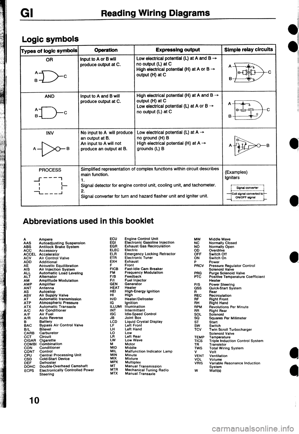
Loaic symbols I
ypes of logic symbols Operation Expressing output Simple relay circuits
OR
Input to A or 8 will Low electricai potential (L) at A and B +
produce output at C. no output (L) at C
A
6
D- High electrical potential (H) at A or B +
C output (H) at C
AND Input to A and B will High electrical potential (H) at A and B +
produce output at C. output(H) at C
q---J-c
Low electrical potential (L) at A or B + A
no output (L) at C
B a-00-a C
6
INV No input to A will produce Low electrical potential (L) at A -+
an output at B. no ground (H) B
An input to A will not High electrical potential (H) at A +
A- 6 produce an output at B. grounds (L) B A- 6
PROCESS Simplified representation of complex functions within circuit describes
main function. (Examples)
---
--I- 1 1. Igniters
I
-L-l Signal detector for engine control unit, cooling unit, and tachometer.
Ii- 2. r”~“-‘-‘-““‘~~‘.“’
Sbnsl conwflw :
i...-..--.---......-.~~
Signal converter for turn and hazard flasher unit and igniter unit.
Abbreviations used in this booklet
A
AAS
ABS
ACC
ACCEL
ACV
ADD
AE
AIS
ALL
ALT
EP
ANT
EV
EP
ATX
A/C
AIF
AIR
:AC
B/L
CARB
CCT
CIGAR
COMBI
CON
CONT
CPU
CSD
DEF
DOHC
ECPS Ampere
Autoadjusting Suspension
Antilock Brake System
Accessory
Accelerator
Air Control Valve
Additional
Acoustic Equilibration
Air Injection System
Automatic Load Leveling
Alternator
Amplitude Modulation
Amplifier
Antenna
Autostop
Alr Supply Valve
Automatic transmission
Atmospheric Pressure
Automatic Transaxle
Air Conditioner
Air Fuel
Auto Reverse
Battery
Bypass Air Control Valve
Bilevel
$rr$:,tor
Cigarette
Combination
Conditioner
Control
Central Procassino Unit
&Id-Start Device -
Defroster
Double-Overhead Camshaft
Electronically Controlled Power
Steering ECU
EGI
EGR
ELEC
ELR
ETR
EXH
E
FICB
FM
F/S
F/I
GEN
ET
HI
H/D
I;LUMl
INT
ISC
JB
LCD
LF
k!
z Engine Control Unit
Electronic Gasoline Injection
Exhaust Gas Recirculation
Electrio
Emergency Locking Retractor
Electronic Tuner
Exhaust
Front
Fast-Idle Cam Breaker
Frequency Modulation
Feedback
Fuel lniector
Generator
Heater
High-Energy Ignition
High
Heater/Defroster
Ignition
lllumlnation
Idle-Speed Control
Joint Box
Liquid Crystal Display
Left Front
Left Hand
Low
Left Rear
Low Wave
:I, Motor
Middle
MIL
MIN Malfunction Indicator Lamp
Minute
MIX
Mixture
MPX Multiplex
ZR Manual Transmission
MTX Mechanical Tuning Radio
Manual .Transaxie PRG
PTC
P/S ass
kc
FIF
. . .
RH
RPM
!2EL
SQ
ST
SW
TCV
TEMP
TICS
TR
TWS
V
VENT
VOL
VRIS
W Middle Wave
Normally Closed
Normally Open
Overdrive
Switch Off
Switch On
Power
Pressure Regulator Control
Solenoid Valve
Purge Solenoid Valve
Positive Temperature Coefficient
Heater
Power Steering
;im&k-Start System
Recirculation
Right Front
Right Hand
Revolutions Per Minute
Right Rear
Solenoid
Squares Per Milimeter
Start
Switch
Twin Scroll Turbocharger
Solenoid Valve
Temperature
Triple Induction Control System
Transistor
Total Wiring System
Volt
Ventilation
Volume
Variable Resonance Induction
System
Watt(s)
IO
Page 192 of 279

Troubleshooting GI
Precautions to take when servicing an electrical system
l Note the following items when servicing the electrical system.
l Do not alter the wiring or electrical equipment in any way; this may damage the vehicle or cause a fire from
short-circuiting a circuit or overloading it. l
The negative (-) battery cable must be removed first and
installed last. l Do not replace with fuses exceeding specified capacity.
1OA
f5A
Zaution
o Be sure that the ignition and other switches are off
Caution
before disconnecting or connecting the battery
l Replacing a fuse with one of a larger capacity than
cables.
designated may damage components or cause a fire.
Failure to do so may damage the semiconductor
components.
0 Tape areas of the
l When mounting l Secure harnesses with provided clamps to take up slack.
harness that may rub or
components, be sure the
bump against sharp
harness is not caught or
edges to protect it from
damaged.
damage.
Zaution
B Clamp all harnesses near vibrating components
(for example, the engine) to remove slack and to
prevent contact resulting from vibration.
D Do not handle electrical components roughly or drop
them.
l Disconnect heat-
sensitive parts (for
example, relays and
ECU) when performing
maintenance (such as
welding) where
temperatures may exceed
80°C (176°F). l Make sure that the
connectors are securely
connected when
installed.
11
Page 194 of 279

Troubleshooting
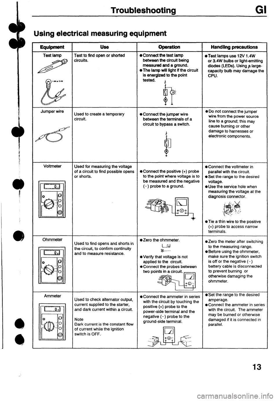
Using electrical measuring equipment
Equipment USe
Test lamp Test to find open or shorted
H circ”its. operation Handling precautions 0 Connect the test lamp l Test lamps use 12V 1.4W
between the circuit being
or 3.4W bulbs or light-emitting
measured and a ground.
diodes (LEDs). Using .a large-
l The lamp will light if the circuit
capacity bulb may damage the
is energized to the point
CPU.
tested.
I? ‘s
n
Jumper wire
Used to create a temporary 0 Connect the jumper wire
l Do not connect the jumper
circuit. between the terminals of a wire from the power source
circuit to bypass a switch. line to a ground; this may
4 cause burning or other
b damage to harnesses or
electronic components.
M
Voltmeter
Used for measuring the voltage
l Connect the voltmeter in
of a circuit to find possible opens *Connect the positive (+) probe
parallel with the circuit.
or shorts.
to the Point where Voltage is to 0 Set the range to the desired
be measured and the negative
voltage.
(-) probe to a ground.
*Use the service hole when
measuring the voltage at the
diagnosis connector.
‘$$
‘, i_ I/
*Tie a thin wire to the positive
(+) probe to access narrow
terminals.
Ohmmeter
l Zero the ohmmeter.
Used to find opens and shorts in *Zero the meter after switching
the circuit, to confirm continuity l-.&j
to the measuring range.
and to measure resistance. -*-.
0 Before using the ohmmeter,
l Verify that voltage is not make sure the ignition switch
applied to the circuit. is off or the negative (-)
l Connect the probes between battery cable is disconnected
two points in a circuit. _ to prevent burning or
otherwise damaging the
ohmmeter.
Ammeter
l Connect the ammeter in series l Set the range to the desired
Used to check alternator output,
with the circuit by touching the amperage.
current supplied to the starter,
and dark current within a circuit. positive (+) probe to the l Connect the ammeter in series
power-side terminal and the with the circuit. The ammeter
Note
Dark current is the constant flow negative (-) probe to the
ground-side terminal. may be burned or otherwise
damaged if it is connected in
parallel.
of current while the ignition
switch is OFF.
13
Page 197 of 279

GI Troubleshooting
FindIng short circuits
Shorts occur between the power (positive) and ground (negative) sides of a circuit.
Therefore, finding a short circuit requires determining how the circuit is routed.
Circuits
not connected to control unit
I
Examples
ihort location 1 SvmWom
I Battery
,pOSlhl
terminal) lgnitbn switch
I Finding short circuit
4
1. Remove the fuse and
main fuse of the circuit.
2. Disconnect ail connecton
Of electrical components in the circuit.
3. Attach a voltmeter or test
Motor
M
Qi!
Short (A)
Short (8)
Short (C)
Short (0) l The motor operates
regardless of whether the
thermoswitch is ON or OFF
when the ignition switch is ..-..
ON. -
@The fuse is not melted.
0 The main fuse melts when the
ignition switch and thermo-
switch are ON and the relay is
operating.
lgnitlon switch
Switch short locatior
Short (A)
Short (B)
Short (C) Test lamp lamp to the fuse box and
reconnect each connector, beginning
nearest the power
, source. Circuits connected to control unit
1 Examples
Symptom
l Fuse melts.
Short (D)
Short (E) 14. Check the voltmeter
reading or test lamp as
the connectors are
connected.
l solenoid A operates when the
ignition switch is ON.
l The CPU transistor burns out
when the ignition switch is
turned ON.
l The CPU thinks the switch is
ON because the same
conditions exist as when the
switch is ON.
@The CPU senses the sensor
to be 0 Q because the same
conditions exist as when the
resistance value is 0 Q.
l The CPU equipped with the
self-diagnosis function outputs
the code. l-
Finding short circuit
1. Remove the fuse and main
fuse of the circuit.
2. Disconnect ail connectors oi
electrical components in the
circuit.
rest lamp 3. Attach a voltmeter or test
lamp to the fuse box and
reconnect each connector,
beginning nearest to the
power source.
Check the voltmeter reading
or test lamp as the
connectors are connected.
Sensor/switch
1. Attach the test lamp or
voltmeter to the CPU
connector.
2. Connect to the switch/
sensor connector.
3. Check the voltmeter reading
voltmeter reads OV or the test lamp
16
Page 209 of 279

I-la1 = ENGINE CONTROL SYSTEM (l/3)
MAIN W/R (F) 0 ocrg\
m BOA JEJJS ROOM “27
rnn L’H(F-=-l ^T.^..^^-^
GNITION
I w
I I C (Fl
JB-04
I W/Y LG/Y W/B
0 (EM) (EM) (EM) (EM)
IA ID 1K lF
(SECTION n-1)
ENGINE CONTROL UNIT
7:: 81-03
IA
64) L .L (EM)
I I
I ’ W/R (EM)
B/W (RI
(EM1
I I B/R EM)
ThiCT”, l.lCIlT
II”.J / ““l~lL,Y I Ii
CLUSTER
(SECTEN cl -G/R +z::
t I I - ,- I
CONTROL SYSTEM
(SECTION B-lb)
I FUEL
B PUMP
(R)
I PUMP RELAY
~-_-, _-.. -, l-01 ENGINE CONTROL UNITtEM)
1” IS 10 10 1M 1K II IG 1E IC i&
R/B O/L G/B G * Xi/ L G/W x V L/R
BR/Y B/L B/G L/Y R/W * L/B O/B W/B W/y W/R
IV lT ,R !P fN IL 1J fH 1F 10 113
L-04 FUEL PUMP(R)
181-05 IGNITER (EM) 2H 2F 2D 28
91-06 CONDENSER (EM)
181-07 IGNITION COIL (EM)
I 8
I
-27 TRANSFER PUMP (Rl 161-28 FUEL PUMP RELAY (EM)
I
Y/L L/Y
B XL I i1-02 MAIN RELAY(E)
81-03 CIRCUIT OPENING
(FUEL INJ) RELAY (EM)
28
Page 215 of 279

1B 0 Main relay
(FUEL INJ r&y)
Ignition switch
(STARI)
1D 0 Self-Diagnosis
Checker
(monitor lamp)
I IJ 0 A/C relay
Ignition switch ON
vs
NC switch ON at idle
6&w 2 54
NC swtch OFF at Idle VB
-
‘“‘~~
System Selector test switch at
I I I
I I I 1L - - - -
- -
IM 1 - 1 - -
I - -
- 1T ThrorUe SW&X
(ii switch)
Foghghl relay
P/S pressure
switch
A/C switch
Electric coding fan
swlch
Blower control
swtch
Rear wlndow
defroster swtch
Neutral/Clutch
switches Tesl condnton
Accelerator pedal released
Accderator pedal depressed -*
B&low l.OV
Vi3
Togllghtsmtcll
Foglight switch OFF
lanitton switch ON V0
OY
VR .-
P/S pressure switch ON at tdle
P/S pressure swtch OFF at I& 6&w 1 .ov
Ye
Fan operatbng (coolant temperature over
97OC I207OF ) or diagnosis connector
Blower control switch OFF or 1st posttion
E~iower conlroi svntch 2nd or higher po-
Rear wndow defroster OFF
Rear wndow defroster ON ~~
Neutral pcsitw or clutch pedal
rlr-n -
Ignition swrlch
ON and biowtr
motor ON -
Ignition switch
ON
Ignition switch
ON
34
Page 216 of 279

Ve:BenyVdhfp
Test condttton
-roliqc lblwk
lgnhn switch ON
VI3
- bmtm
2A
28
x
2D
2E
2F
26
2H
21
2J
2K
21
2M
2N
20
2P
20
2R Test condtthw
ranabla
2s
2T
2u
2v
2W
2x
2Y
arm-up)
P
P
8°F) P
ov
ov
ov
ov
ov of sv
Approx. 2v
-
ov or 5v
tpplox. 1.5
- connected to
oveftmost warning
tluzz.af
I
I
i”e started wilh cootanl 1 Below 1.5V 1 No&ad engine 1Bo sec. alter eng
temperature is above 90% 1194°F ) and
CondilkJn
iniake air temperature is between 40%
I l@i°F) and So% (122OFj
Other condition at idle
VB
lgrition switch ON
L VE ‘Engine Signd
Idle
VFJ’ Monitor: Green
Engine speed above 2.ooO rpm during
VE and red lamps
Nash Sde”&d valve
m kw tap.)
deceteralion (alter warm-up) -
-
0 -
lanition switch ON -
-
-
-
0 lnjedor (Nos. 1. 3) -
Ignition switch ON
Idle
injector (Nos 2. 4) IgrMon switch ON
I -3 Va
I
ISC valve -
-
0
0
-
0
0
0
0
-
0
0
-
- Idle -
Lpprox. 4.01
4.!--5sv
0 of 5v Knock control unit
Engine speed above 2,GOD rf
Thio#e sensor/
Airllow mder Constant -
0 Solenoid valve
(purge conlro4) Ignition switch ON
II
-
I* I “la I
lgnitlon switch ON .-.- ._
lgnitiin swilch ON VB
-
Idle Below 1.w
210 sec. alter engine started with coolant Below 1.5V No&d engine
temperature above 90% ( 194OF) and
cofditlon
intake air temperature above 50°C
/122OF)
Other condition al idle Va - 0
0 Qrcuit-oparing
relay
sdenoid valve
(PRC high temp.) Accelerator pedal released
Accelerator pedal lully depfesw ,pprox. 0.5L
.pprox. 4.oi 22 -
1 J
Is- r,
L-7 r
2Y Zw 2U 2s 20 20 ZM 2K 21 2G 2E 2C ZA 1U IS 10 10 1M tK I, tG 1E ,C ,A
22 2X ZV 2T ZR 2P 2N 2L 2J 2H ZF 20 28 1V IT IF! ,P IN 1L 1J t” 1F 10 19 lamlion switch ON
Idle (cold engine)
Idle (alter warm-up) ov
o-l.OV
0.5-l.OV
o-0.4v
xpprox. 3.8
tipprox. 3.0
tpprox 2.5
bpprox. 2.5
Bdow 0.5v
V8 -
lncreasmg engine speed (after w
Deceleralion
lgnltro” switch ON Airllow meter -
n airflow meter intake aa
Ambient air temperalure 20°C (6
ErlQl”l? codant temperature 200(
Alter warm-up
Ignition switch ON Water
thermosensor
To&charge
rndlcator
1 I
UI “I
u-1 r
-
2Y ZW ZU ZS 20 20 2M ZK 21 2G 2E 2C ZA lU IS 10 10 1f.I 1K 11 1G 1E tC 1A
22 2X 2V 27 2P 2P 2N 2L 2J 2H ZF 2D 28 IV IT IA 1P IN IL 1.1 1H 1F ID It3
35
Page 238 of 279

NARNESS SYMBOL : z (FJ m (E) a (I) m (R) *(OFI)- (IN) ‘*t (FFi)* (EM)= (INJ)
F-2 1
/ E-12
FUSE BOX
MA,N FUSE IGNITION
SWITCH
CONNECTOR
/ / F-07 STOWGHT
LH
JOINT BOX