heater MAZDA 323 1992 Workshop Manual Suplement
[x] Cancel search | Manufacturer: MAZDA, Model Year: 1992, Model line: 323, Model: MAZDA 323 1992Pages: 279, PDF Size: 24.15 MB
Page 2 of 279
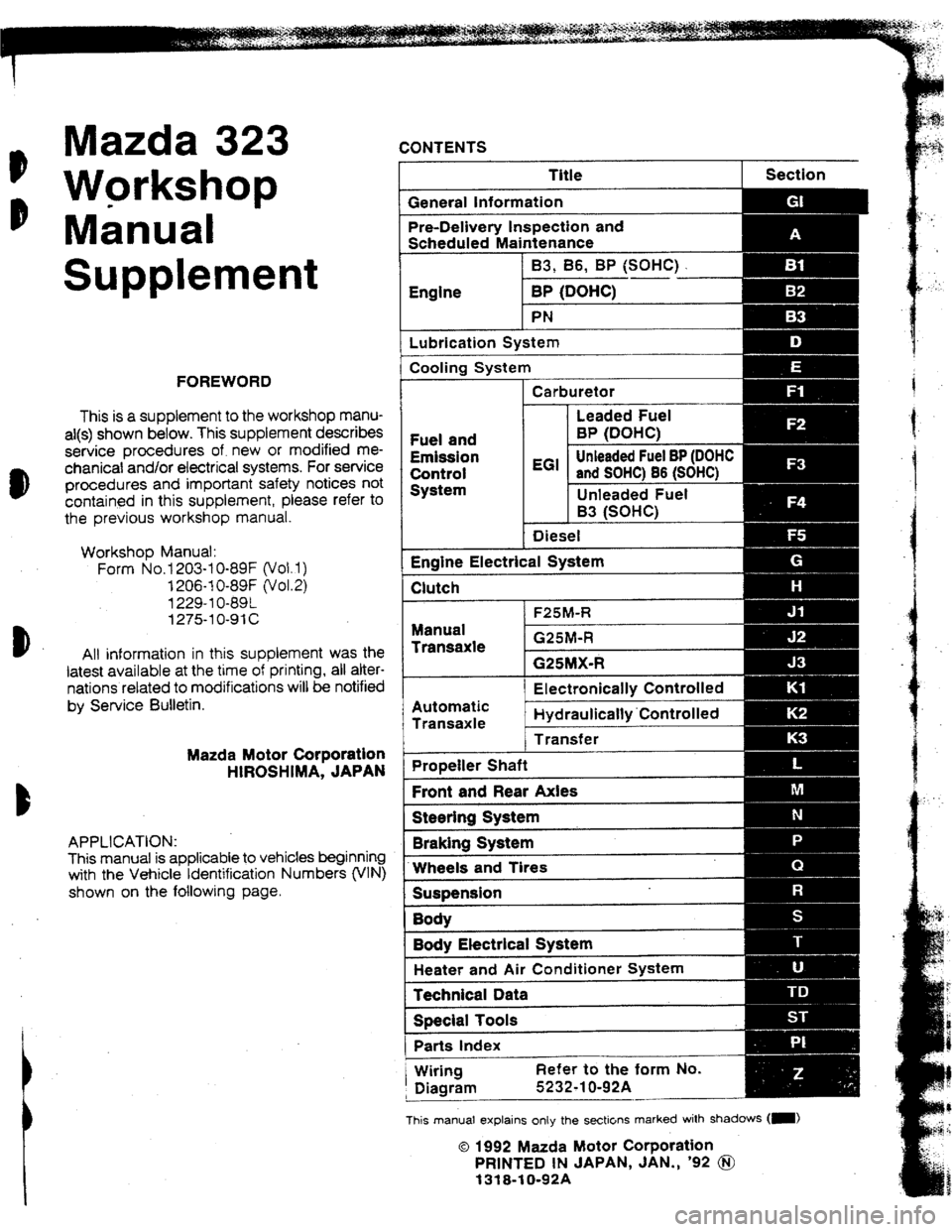
Mazda 323
o Workshop
b Manual CONTENTS
r Title Section
IG eneral Information
Pre-Delivery inspection and
Scheduled Maintenance
Supplement
I Lubrication System
j Cooling System
FOREWORD
This is a supplement to the workshop manu-
a!(s) shown below. This supplement describes
service procedures of. new or modified me-
chanicat and/or ekctrical systems. For service
procedures and important safety notices not
contained in this supplement, please refer to
the previous workshop manual.
Workshop Manual:
Form No.1 203-l O-89F (vol. 1)
1206-1 O-89F (Vol.2)
1229-l O-89L
1275-l O-91 c
b
All information in this supplement was the
latest available at the time of printing, ail alter-
nations related to modifications will be notified
by Service Sulletin. Carburetor
m !I
Fuel and
Emission
Controt
System EGi unieaded Fuel BP (DOHC
and S
Diesel
-Electrica I System
I-- Clutch
Manual
Transaxie
1 Electronically Co Introlled
I
Automatic
Transaxle Hydraulicaf~y’Co~~~rull=;u
1 Transfer
Mazda Motor Corporation
HIROSHIMA, JAPAN [ Propefier Shaft
1 Front and Rear Axles
P ISteerIng System
APPLICATION:
This manual is applicable to vehicles beginning
with the Vehicle Identification Numbers (VIN)
shown on the following page. Braking System
IWheels and Tires
ISusiension
1 Bodv Electricat System
1 Heater and Air Conditioner System
1 Technical Data
Special Toots
Parts Index
/ Wiring Refer to the form No.
, Diagram 5232-l 0-92A
--
This manual explains onty the secticlns marked with shadows (-1
0 1992 Mazda Motor Corporation
PR1NTED tN JAPAN, JAN., ‘92 @I
1318010192A
Page 21 of 279
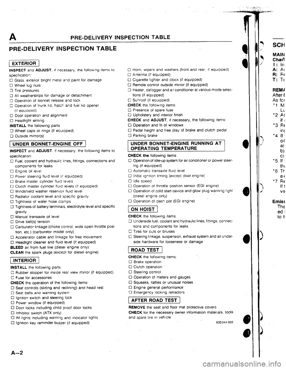
A PRE-DELIVERY INSPECTION TABLE
PRE-DELIVERY INSPECTION TABLE
[EXTERlORI
INSPECT and ADJUST, of necessary. the followlng Items to
specrfrcatron:
0 Glass, exterior bright metal and paint for damage
0 Wheel lug nuts
0 Tire pressures
0 All weatherstrips for damage or detachment
0 Operation of bonnet release and look
0 Operation of trunk Ild, hatch and fuel lbd opener
(of equipped)
0 Door operation and alignment
0 Headtrght aiming
INSTALL the foltowrng parts
0 Wheel caps or rrngs (if equipped)
0 Outsrde mirror(s)
1 UNDER BONNET-ENGINE OFF j
INSPECT and ADJUST. If necessary, the following items to
specrflcatlon.
0 Fuel, coolant and hydraulic tines, fittings, connectlons and
components for leaks
0 Engine 011 level
0 Power steering fluid level (of equipped)
0 Brake master cylinder fluky levels
0 Clutch master cylinder fturcl levels (If equipped)
0 Wtndshreld washer reservojr flurd level
0 Radiator coolant level and specrfic gravity
0 Tightness of water hose clamps
0 Tightness of battery terminals, electrolyte level and specific
gravity
0 Manual transaxle oil level
0 Drive belt(s) tension
Cl Carburetor lrnkage (choke control, wrde open throttle posi-
tion. etc ) (carburetor model only)
q Accelerator cable and linkage for free movement
0 Headlight cleaner and flurd level (if equipped)
BLEED air from fuel line (diesel engrne only)
CLEAN the spark plugs (except for diesel engine)
piEi6F]
INSTALL the following parts
0 Rubber stopper for rnsrde rear view mirror (if equjpped)
0 Fuse for accessories
CHECK the operation of the following items.
0 Seat controls (sliding and reclining) and head rest
0 Seat belts and warning system
Cl Ign&on switch and steering lock
0 Power window (if equipped)
D Door tacks including child proof door locks
Cl Inhibitor switch (ATX only)
Cl All Ikghts rncluding warning and Indicator lbghts
0 Ignition key reminder buzzer (If equipped)
A-Z
0 Horn, wbpers and washers (front and rear, If equipped)
0 Antenna (tf equipped)
0 Cigarette Ibghter and clock (if equipped)
0 Remote control outside mirror (if equrpped)
0 Heater, defogger and air conditioner at various mode selec-
tions (if equlppedj
0 Sunroof (If equipped)
CHECK the following items
0 Presence of spare fuse
0 Upholstery and Interior finish
CHECK and ADJUST, If necessary, the followjng items:
IJ Operation and fit of windows
0 Pedal height and free play of brake and clutch pedal
0 Parking brake UNDER BONNET-ENGINE RUNNING AT
OPERATING TEMPERATURE
CHECK the following items:
0 Operation of Idle-up system for air condbtroner or power steer-
ing (if equrpped)
0 Automatic transaxle flurd levet
0 tnltial ignrtlon timing (except disel engine)
0 Idle speed
0 Operation of throttle positron. sensor (EGI engrne)
0 Operation of cold start device and glow plug warning light
(diesel engine only)
0 Operation of dash pbt (EGI.engine)
fTiGGJ
CHECK the following items.
0 Underside fuel, coolant and hydraulic Irnes, ftttlngs, connec-
tions and components for leaks
0 Trres for cuts or brurses
0 Steering Itnkage, suspensron, exhaust system and all under-
side hardware for .looseness or damage 1 ROAD TEST j
CHECK the following items
0 8rake operation
0 Clutch operation
0 Steering control
!ZI Operation of meters and gauges
Cl Squeaks, rattles or unusual noises
Cl Engine general performance
0 Emergency locking retractors 1 AFTER ROAD TEST ]
REMOVE the seat and floor mat protective covers
CHECK for the necessary owner information materials, took
and spare tire
m vehicle
93EOAX-002
-- MAIN Char3 t: In
A: PC R: F!t T: Ti! Emis! The ed : to t!
Page 179 of 279
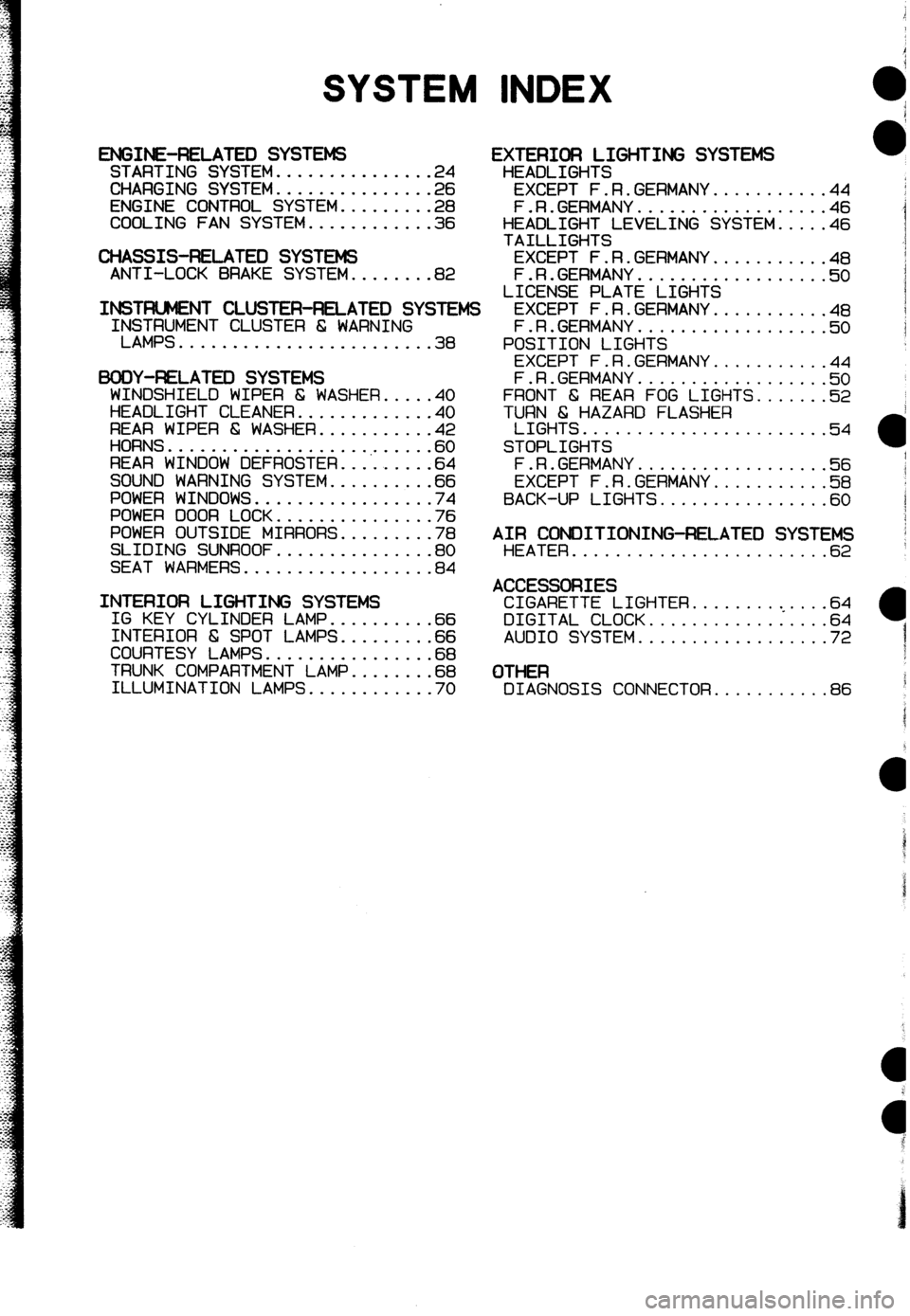
SYSTEM INDEX
ENGINE-RELATED SYSTEMS STARTING SYSTEM...............2 4
CHARGING SYSTEM...............2 6
ENGINE CONTROL SYSTEM.........2 8
COOLING FAN SYSTEM............3 6
CHASSIS-RELATED SYSTEMS ANTI-LOCK BRAKE SYSTEM........82
INSTFUJMENT CLUSTER-RELATED SYSIEMS IrS$;MENT CLUSTER 6 WARNING
........................ 38
BODY-F&LATEX) SYSTEMS
WINDSHIELD WIPER 6 WASHER.....4 0
HEADLIGHT CLEANER.............4 0
REAR WIPER & WASHER...........4 2
HORNS...................,......6 0
REAR WINDOW DEFROSTER.........6 4
SOUND WARNING SYSTEM..........6 6
POWER WINDOWS.................7 4
POWER DOOR LOCK...............7 6
POWER OUTSIDE MIRRORS.........7 8
SLIDING SUNROOF...............8 0
SEAT WARMERS..................8 4
INTERIOR LIGHTING SYSTEMS IG KEY CYLINDER LAMP..........6 6
INTERIOR 6 SPOT LAMPS.........6 6
COURTESY LAMPS................6 8
TRUNK COMPARTMENT LAMP........6 8
ILLUMINATION LAMPS............7 0
EXTERIOR LIGHTING SYSTEMS
HEADLIGHTS
EXCEPT F.R.GERMANY...........44
F.R.GERMANY..................46
HEADLIGHT LEVELING SYSTEM.....46
TAILLIGHTS
EXCEPT F.R.GERMANY...........48
F.R.GERMANY..................5 0
LICENSE PLATE LIGHTS
EXCEPT F.R.GERMANY...........4 8
F.R.GERMANY..................5 0
POSITION LIGHTS
EXCEPT F.R.GERMANY...........4 4
F.R.GERMANY..................!i? 0
FRONT 6 REAR FOG LIGHTS.......52
TURN 6 HAZARD FLASHER
LIGHTS.......................54
STOPLIGHTS
F.R.GERMANY.a................5 6
EXCEPT F.R.GERMANY...........5 8
BACK-UP LIGHTS................6 0
AIR CONDITIONING-RELATED SYSTEMS HEATER........................6 2
ACCESSORIES CIGARETTE LIGHTER.........<....64
DIGITAL CLOCK.................64
AUDIO SYSTEM..................72
OTHER DIAGNOSIS CONNECTOR...........86
Page 185 of 279
GI Reading Wiring Diagrams
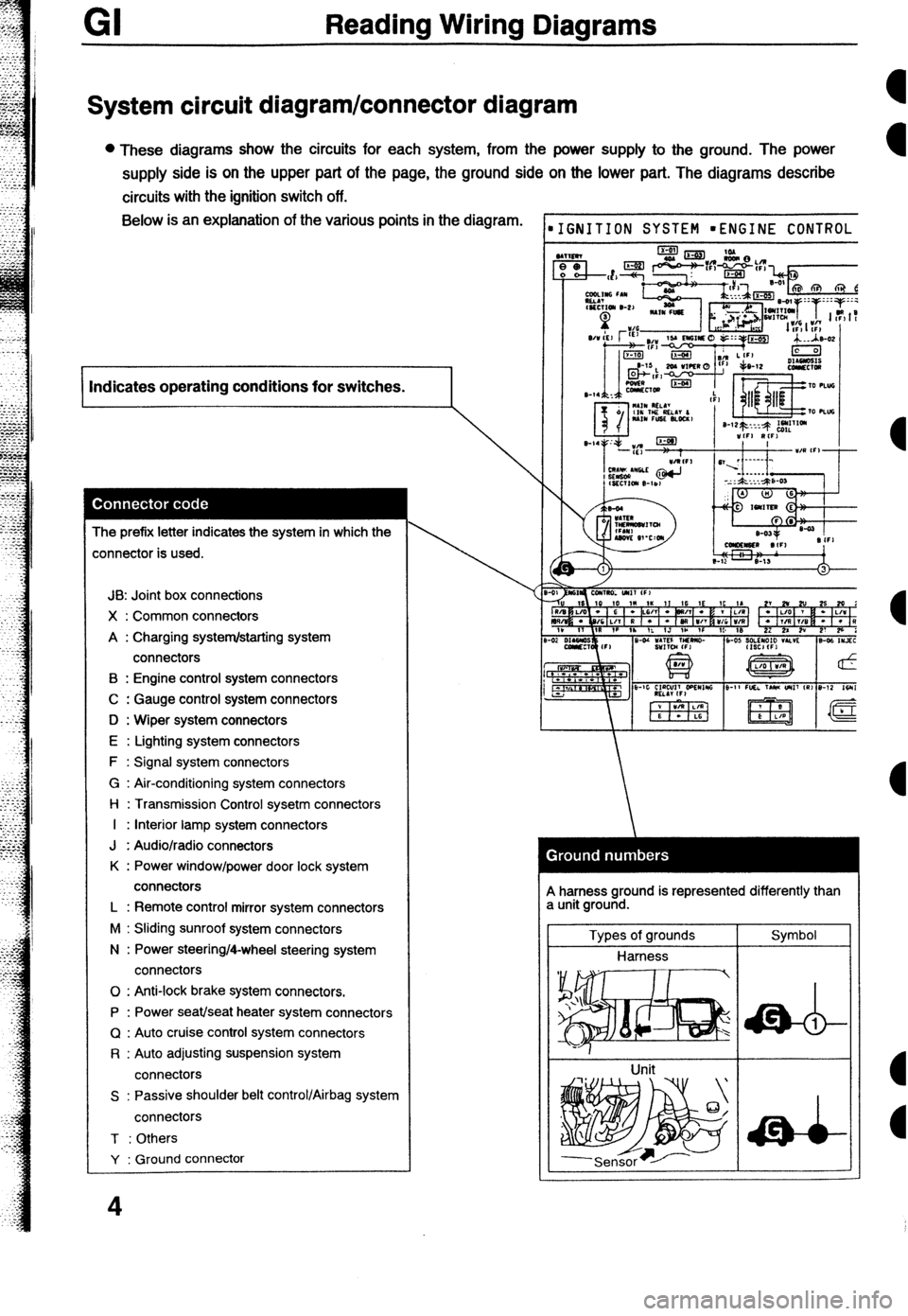
System circuit diagram/connector diagram
l These diagrams show the circuits for each system, from the power supply to the ground. The power
supply side is on the upper part of the page, the ground side on the lower part. The diagrams describe
circuits with the ignition switch off. Below is an explanation of the various points in the diagram.
I Indicates operating conditions for switches.
I
The prefix letter indicates the system in which the
:onnector is used.
JB: Joint box connections
X : Common connectors
A : Charging system/starting system
connectors
B : Engine control system connectors
C : Gauge control system connectors
D : Wiper system connectors
E : Lighting system connectors
F : Signal system connectors
G : Air-conditioning system connectors
l-l : Transmission Control sysetm connectors
I : Interior lamp system connectors
J : Audio/radio connectors
K : Power window/power door lock system
connectors
L : Remote control mirror system connectors
M : Sliding sunroof system connectors
N : Power steering/4-wheel steering system
connectors
0 : Anti-lock brake system connectors.
P : Power seat/seat heater system connectors
Q : Auto cruise control system connectors
R : Auto adjusting suspension system
connectors
S : Passive shoulder belt control/Airbag system
connectors
T : Others
Y : Ground connector
4
IGNITION SYSTEM mENGINE CONTROL
A harness ground is represented differently than
a unit ground.
Types of grounds
Harness
Unit Symbol
Page 190 of 279

-
Reading Wiring Diagrams GI
Symbol
Horn Meaning l Generates sound when current flows. Symbol Switch (1) Meaning l Allows or breaks current flow by
opening and closing circuits.
Speaker
ccl
Heater l Generates heat when current flows. Normally open (NO)
Switch (2)
I
Normally closed (NC)
Harness l Unconnected intersecting harness.
Speed sensor
+ Movement of magnet in speedometer
turns contact within sensor on and off. (Not connected)
w Connected intersecting harness.
Ignition switch
l Turning ignition key switches circuit to
operate various component.
(Connected)
Relay (1)
l Current flowing through coil produces electromagnetic force causing contact to open or close.
No current to coil Current to coil
Uormally open (NO)
Relay (2) Normally open relay (NO)
lormally closed (NC) [/I jr No flow @jj 1 Flow
Normally closed relay (NC)
Sensor (variable) a Resistance changes with other Diode l Known as a semiconductor rectifier,
components operation. the diode allows current flow in one
IA direction only.
R
CaIhode(K)--++- Anode(A)
- Flow 01 electric C”llO”,
KIIZT)-A K-A K-A
#ensor (thermistor) 0 Resistance changes with temperature. Light-emitting diode l A diode that lights when current flows.
V-ED) l Unlike ordinary bulbs, the diode does
not generate heat when it.
%u
I-
- Cathode(K) -$----- Anode(A)
Capacitor
l Component that temporarily stores
electrical charge.
----it----
Flow of current
Solenoid
l Current flowing through coil generates Reference diode l AIIOWS current to flow in one direction
electromagnetic force to operate (Zener diode) up to a certain voltage; allows current
to flow in the other direction once that
ti
n voltage is exceeded.
9
Page 191 of 279
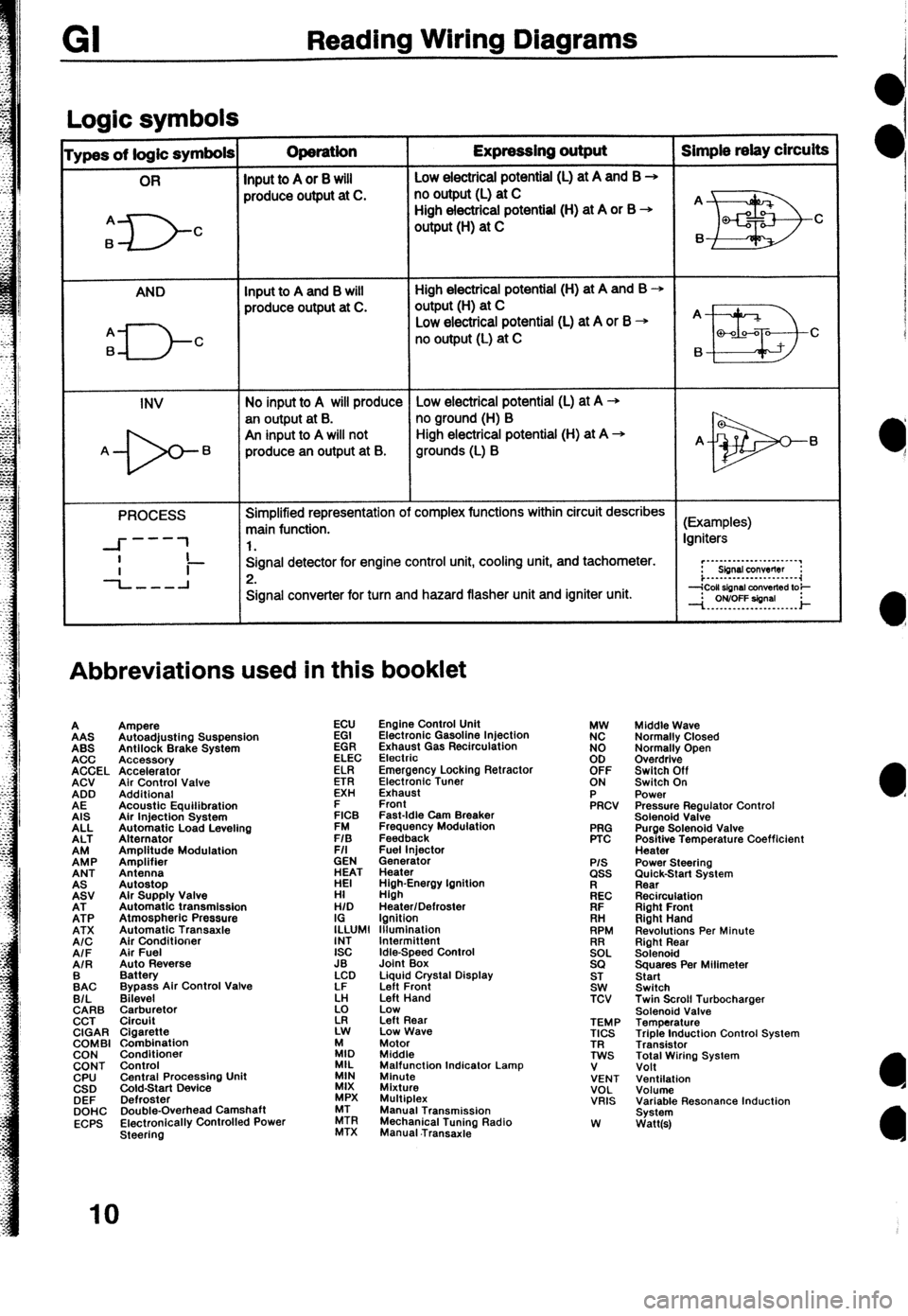
Reading Wiring Diagrams
Loaic symbols I
ypes of logic symbols Operation Expressing output Simple relay circuits
OR
Input to A or 8 will Low electricai potential (L) at A and B +
produce output at C. no output (L) at C
A
6
D- High electrical potential (H) at A or B +
C output (H) at C
AND Input to A and B will High electrical potential (H) at A and B +
produce output at C. output(H) at C
q---J-c
Low electrical potential (L) at A or B + A
no output (L) at C
B a-00-a C
6
INV No input to A will produce Low electrical potential (L) at A -+
an output at B. no ground (H) B
An input to A will not High electrical potential (H) at A +
A- 6 produce an output at B. grounds (L) B A- 6
PROCESS Simplified representation of complex functions within circuit describes
main function. (Examples)
---
--I- 1 1. Igniters
I
-L-l Signal detector for engine control unit, cooling unit, and tachometer.
Ii- 2. r”~“-‘-‘-““‘~~‘.“’
Sbnsl conwflw :
i...-..--.---......-.~~
Signal converter for turn and hazard flasher unit and igniter unit.
Abbreviations used in this booklet
A
AAS
ABS
ACC
ACCEL
ACV
ADD
AE
AIS
ALL
ALT
EP
ANT
EV
EP
ATX
A/C
AIF
AIR
:AC
B/L
CARB
CCT
CIGAR
COMBI
CON
CONT
CPU
CSD
DEF
DOHC
ECPS Ampere
Autoadjusting Suspension
Antilock Brake System
Accessory
Accelerator
Air Control Valve
Additional
Acoustic Equilibration
Air Injection System
Automatic Load Leveling
Alternator
Amplitude Modulation
Amplifier
Antenna
Autostop
Alr Supply Valve
Automatic transmission
Atmospheric Pressure
Automatic Transaxle
Air Conditioner
Air Fuel
Auto Reverse
Battery
Bypass Air Control Valve
Bilevel
$rr$:,tor
Cigarette
Combination
Conditioner
Control
Central Procassino Unit
&Id-Start Device -
Defroster
Double-Overhead Camshaft
Electronically Controlled Power
Steering ECU
EGI
EGR
ELEC
ELR
ETR
EXH
E
FICB
FM
F/S
F/I
GEN
ET
HI
H/D
I;LUMl
INT
ISC
JB
LCD
LF
k!
z Engine Control Unit
Electronic Gasoline Injection
Exhaust Gas Recirculation
Electrio
Emergency Locking Retractor
Electronic Tuner
Exhaust
Front
Fast-Idle Cam Breaker
Frequency Modulation
Feedback
Fuel lniector
Generator
Heater
High-Energy Ignition
High
Heater/Defroster
Ignition
lllumlnation
Idle-Speed Control
Joint Box
Liquid Crystal Display
Left Front
Left Hand
Low
Left Rear
Low Wave
:I, Motor
Middle
MIL
MIN Malfunction Indicator Lamp
Minute
MIX
Mixture
MPX Multiplex
ZR Manual Transmission
MTX Mechanical Tuning Radio
Manual .Transaxie PRG
PTC
P/S ass
kc
FIF
. . .
RH
RPM
!2EL
SQ
ST
SW
TCV
TEMP
TICS
TR
TWS
V
VENT
VOL
VRIS
W Middle Wave
Normally Closed
Normally Open
Overdrive
Switch Off
Switch On
Power
Pressure Regulator Control
Solenoid Valve
Purge Solenoid Valve
Positive Temperature Coefficient
Heater
Power Steering
;im&k-Start System
Recirculation
Right Front
Right Hand
Revolutions Per Minute
Right Rear
Solenoid
Squares Per Milimeter
Start
Switch
Twin Scroll Turbocharger
Solenoid Valve
Temperature
Triple Induction Control System
Transistor
Total Wiring System
Volt
Ventilation
Volume
Variable Resonance Induction
System
Watt(s)
IO
Page 201 of 279
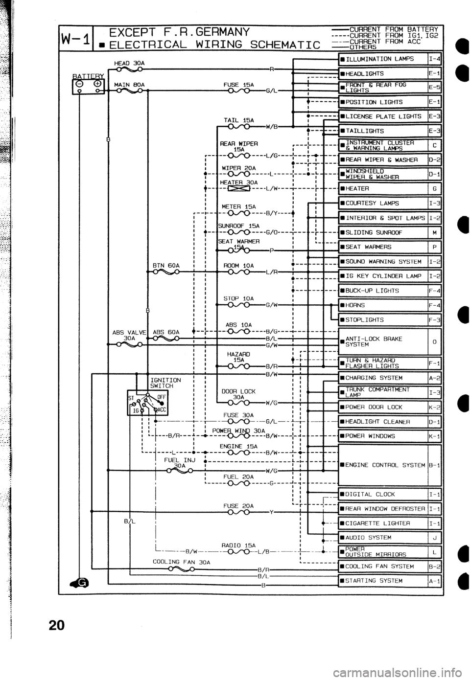
d-II __ EXCEPT F.R.GERMANY -CURRENT FROM BATTERY
-----CURRENT FROM IGl. IG2
-I 1--~-l-l-a-r-~ A, ,.,TiTl-TLITr r-.-a ar.1. ?I,-% ----CIJARENT FROM ACC
“-‘e 30A
I -mILLUMINATION LAMPS I-4
HiZP
r--- “f E-l
MAIN 00A FUSE l5A
q
-GA- I’LIE iHTS
---mm_
n POSITION LIGHTS E-l
TAIL 15A
-W/B
I
+-.
i-. I
i REAR WIPER
15A
-0J‘o ---- L/G _--- ;-.-&+v ---.
WIPER 20A .---$- ---. l REAR WIPER E WASHER o-2
m--c____ L _____ ;--:-; ____. l ;:E;H;E:;SHm
O-l
HEATER 30A
-- _-__ ,,,-j __-__; --me., HEATER
G
t
METER 15A : - - l COURTESY LAMPS I-3
-------B/y ---- + I
ZiUNROOF 15A : --•INTERIOR 6 SPOT LAMPS I-2
t
-oJy)--
G/O---:--- -t----.mSLIOING SUNROOF M
~~~~ .--- __ ___ n SOUN0 WARNING SYSTEM I-2
48s VALV
30A I
i
AES 60A +--t-
I mSTOF’LIGHTS F-3
ABS iOA
--- ’ ‘I ---
GNITION ! ;
iWITCH 1 I
TRUNK COMPARTMENT
‘LAMP I-3
‘mPOWER DOOR LOCK A
K-2
FUSE 30A
y-------t- --~--G/!---j--& .--- - l HEADLIGHT CLEANER O-l
I
’ . ---B/R---+-* ----
K-l
I PowE~~om!,IJ,+~~ -..---- -...;PO,.,ER WI,.,,,OWS
! I ENGINE 15A
’ I (’ I :
:.
.--
1 ----L ---- l -* ---- OJY) ---- FJ,w----l-q -..--
FUEL INJ ’ .-------------------:-L.---
’ I UENGINE CONTROL SYSTEM B-l
FUSE 20A
l REAR WINOOW DEFROSTER I-l
-- mCIGARETTE LIGHTER I-l
mAUOI0 SYSTEM J
aSTARTING SYSTEM A-l
Page 202 of 279
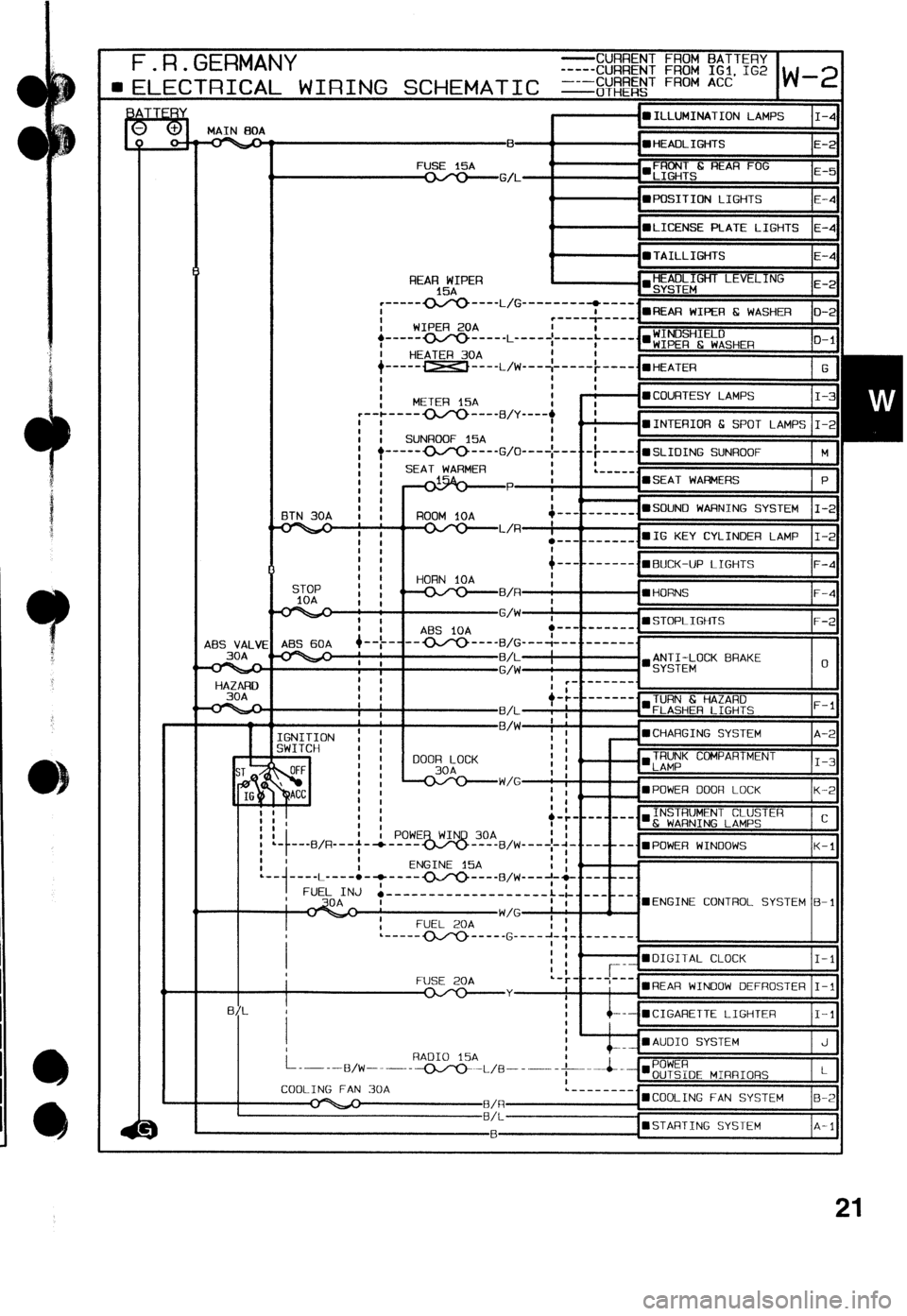
,c -
-
3
F.R.GERMANY F.R.GERMANY -CURRENT FROM BATTERY -CURRENT FROM BATTERY
-----CURRENT FROM IGl. 1G2 -----CURRENT FROM IGl. 1G2
l
ELECTRICAL WIRING SCHEMATIC =&$&jT FRoM ACC l ELECTRICAL WIRING SCHEMATIC =&$&jT FRoM ACC w-2 w-2
I I l ILLUMINATION LAMPS l ILLUMINATION LAMPS
MAIN BOA MAIN BOA , ,
485 VALVI
30A
HAZARO
30A ET’&” REAA FOG
i il E-5
t ‘=POSITION LIGHTS E-4
0
n LICENSE PLATE LIGHTS E-4
i ’ l TAILLIGHTS E-4
!rJJ:GHT LEVELING
.
i il E-2 REAR WIPER
15A a....*.
--- ~--
4
~FIEAR WIPER 6 WASHER i il o-2 I ----- - ---_ L/G _--...----A-___ 7
I WIPER 20A
,---.... - ----_ L ----
I
HEATER 30A
+-----w-.-L/W-+ -----; --__. l ,,,ZATER
G
I I
I
I METER 15A
I - l COURTESY LAMPS I-3
,--+ ---- (xro ---- FJ,y ----, I
I : I -mINTERIOR 6 SPOT LAMPS
I I SUNROOF 15A I I-2
b----------G/o ---- [ ---..- ~----,mSLIOING
I I SUNROOF
I
i i
I I SEAT WARMER
I
I I +g&)
ETN 30A t : ROOM 1OA
; ; i I ,
I : &---------,WBUCK-UP LIGHTS F-4
I
HORN iOA
STOP :
l- : !
.^. t , B/R l HORNS F-4
I , ABS iOA
- ~-
ABS 60A
9--t-“---
1 t
I :
t
I 1
FLASHER LIGHTS STOPLIGHTS
CHARGING SYSTEM
TRUNK COMPARTMENT
POWER DOOR LOCK K-2
INSTRUMENT CLUSTER
6 WARNING LAMPS C
?:m-“_“_“.B/W ---- +.+,v.-{~POWE~ ,.,INOOWS
K-l
l i .-m-e_ cx/v _____ G _-__ +.:m.
I , i il I-l
L_-----_-, l COOLING FAN SYSTEM B-2
B/L---------------------
R l STARTING SYSTEM A-l
21
Page 243 of 279

G l HEATER
MAIN
RESISTOR ASSEMBLY
1 1 1 1
BLOWER SWITCH
ILLUMINATION LAMP
:REFER TO SECTION I-4
Page 275 of 279

0 .F.R.GERMAN~
0 _. .F.R.GERMANY
JB mJB CONNECTORS LOCATION
m JOINT BOX *....ABS
JB-01 ,I;td;gR iAMP JB-02 INSTRUMENT PANEL HARNESS
JB-04
JB-01
JB-06
JB-02 JE-05
JB-07
JB-04 FRONT HARNESS JB-05 FRONT HARNESS
JB-09 JB-08
JB-06 FRONT HARNESS JB-07 FRONT HARNESS
JB-03
J%-08 FRONT HARNESS
‘I B * X X
0 C/B *
H G F E D C B A
REAR WIPER 15A
HAZARD 15A (HORN
IOA)
ROOM iOA
ENGINE 15A
RADIO
15A
DOOR LOCK 30A
SEAT WARMER lSA(TAIL RH
IOA)
POWER WIND 30A
METER
15A
WIPER 20A
STOP 1OA (SEAT WARMER
15Ai
TAIL 15A (TAIL LH
lOA
SUN ROOF 15A
ABS IOA
FUEL 20A
HEATER 30A JB-09 CPU
PONMLKJIHGFEOCBA