relay MAZDA 323 1992 Workshop Manual Suplement
[x] Cancel search | Manufacturer: MAZDA, Model Year: 1992, Model line: 323, Model: MAZDA 323 1992Pages: 279, PDF Size: 24.15 MB
Page 17 of 279

..,. .
a
._
GI CAUTKN
PRECAUTIONS TO TAKE WHEN SERVICING AN ELECTRICAL SYSTEM l Note the following items when servicing the electrical system.
l Do not alter the wiring or electrical equipment in any way; this may damage the vehicle or cause a fire
from short-circuiting a circuit or overloading it.
l The negatrve (-) battery cable must be removed first and
rnstalled last. l Do not reptace with fuses exceedrng specified capacity
Cautron
l 8e sure that the ignitton and other switches are off
before disconnectrng or connecting the battery cables.
Failure to do so may damage the semrconductor
components. Caution l Repfacing a fuse with one of a larger capacrty than
desrgnated may damage components or cause a frre.
l Secure harnesses with provrded clamps to take up slack. l Tape areas of the harness
that may rub or bump l When mounting
components, be sure the
against sharp edges to
protect rt from damage. harness IS not caught or
damaged.
Caution
l Clamp all harnesses near vibratrng components (for
example, the engine) to remove slack and to prevent
contact resultrng from vibration. i Drsconnect heatsensitive l Make sure that the
parts (for example, relays
and ECU) when performing connectors are securely
connected when installed.
l Do not handle electrical components roughly or drop
them. maintenance (such as
weldrng) where
temperatures may exceed
80°C [176OFj.
-*
HI
Page 34 of 279

F3
c
FUEL AND EMISSION
CONTROL
SYSTEMS
i
INDEX . . . . . . . . l ..,.... *..,. . . . . . . m...*.*...*..... F3- 2
UUTLtNE
...................................... F3- 4
OUTLINE OF CONSTRUCTION.. ....
F3- 4
SYSTEM DIAGRAM ...................... F3- 5
VACUUM HOSE ROUTING
DIAGRAM
................................. F3- 6
WIRING DIAGRAM.. .....................
F3- 7
ECU RELATIONSHIP DIAGRAM ...... F3- 8
SPECIFICATIONS.. ....................... F3- 9
TURBOCHARGER CONTROL .......... F3-IO
OUTLINE
.................................... F3-10
SYSTEM DIAGRAM ...................... F3-10
WASTEGATE CONTROL ............... F3-11
FUEL SYSTEM
.............................. F3-12
OUTLINE ....................................
F3-12
CONTROL SYSTEM .......................
F3-13
STRUCTURAL VIEW .....................
F3-13
PRESSURE REGULATOR
CONTROL SYSTEM ....................
F3-14 SUPPLEMENTAL SERVICE
tNFOF?MATtON
............................. F3-I 5
SELF-DtAGNOStS FUNCTtON.. ........
F3-16
OUTLINE ....................................
F3-16
SERVICE CODE NUMBERS..
......... F3-16
TROU8LESHOOTtNG GUtDE
........... F3-19
RELATIONSHtP
CHART.. F3-19 ..............
DIAGNOSTIC JNDEX
.................... F3-20
PRECAUTIONS
............................
F3-21
SYMPTOM TROUBLESHOOTING .... F3-22
TURBOCHARGERCONTROL
SYSTEM ......................................
F3-37
TURBOCHARGER F3-37 ........................
WASTEGATE SOLENOID VALVE.. .. F3-38
INTERCOOLER ............................
F3-39
FUELSYSTEM ..............................
F3-40
FUEL PUMP ................................
F3-40
FUEL PUMP RESISTOR/RELAY ......
F3-40
PRESSURE
REGULATOR .............. F3-41
INJECTOR ..................................
F3-42
INJECTOR RESISTOR
................... F3-42
PRESSUR REGULATOR CONTROL
SYSTEM ......................................
F3-43
SOLENOID VALVE (PRESSURE
REGULATOR CONTROL)
............. F3-43
CONTROL SYSTEM
....................... F3-44
PREPARATION ............................ F3-44
ENGINE CONTROL UNIT (ECU) ..... F3-45
7 3EOF3-301
Page 36 of 279

INDEX F3
t
3EOf3.303
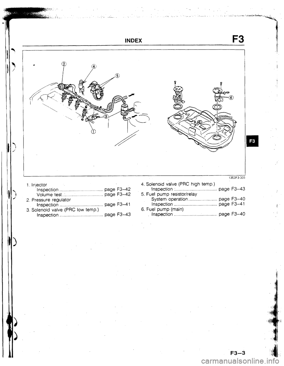
1. Injector 4. Solenoid valve (PRC high temp.)
Inspection ................................. page F3-42 Inspection ;. ............................... page F3-43
Volume test.; ............................. page F3-42 5. Fuel pump resistor/relay
2. Pressure regulator System operation ...................... page F3-40
Inspection ................................. page F3-4 1 Inspection ....... . .........................
page F3-4 1
II
3. Solenoid valve (PRC low temp.) 6. Fuel pump (main)
Inspection ................................. page F3-43 Inspection .......... . ...................... page F3-40
Page 37 of 279

F3 OUTLINE
OUTLINE
OUTLINE OF CONSTRUCTION
Theefuel and emission control system of the new 323 4WD model 1s basically the same as that of the prevr-
ous 323 4WD model; however some parts are changed. The changed parts and interchangable parts
are shown betow.
13EOF3-304
Changed parts
1 ~ components Contents and purpose Reference pagl
INTAKE AlR
SYSTEM Turbocharger
Intercooler
l Size Increased for greater boost pressure l Wastegate solenord valve IS lozated on Intake port of F3-10
turbocharger to make system more compact F3-37
Volume increased for Improved F3-10
t F3-39
Wastegate sojenold valve
l Wastegate solenoid valve changed to duty solenoid
type for Increased engine power and response
l Wastegate solenoid valve is located on Intake port of
turbocharger to make system more compact F3-1 f
F3-38
I r
Pressure regulator One-stage operattlon changed to two-stage operatron F3-14
to improve hot restarting f3-41
L
FUEL SYSTEM High-ohmic type change to low-ohmrc type with exter-
Fuel qector na solenoid reslstor for improved fuel supply during F3-12
high-speed driving F3-42
Fuel pump reslstor Resistance reduced for
surer fuel supply F3-40
CONTROL
SYSTEM Pressure
regulator control system
Atr flow meter Two-stage operatton used to Improve hot restarting
Measures larger amount of air flow Increased power
Resistance values changed F3-t4
F3-43
F3- 9
f3EOF3-305 lnterchangable parts
tntake air system
l
Air valve
l Air bypass valve
l Air cleaner
l Air cleaner element
Fuel system
l Fuel filter assembly
l Fuel pu.mp (transfer
l Fuel vapor valve Control system
. l Throttle sensor
l Water thermosensor
l Knock sensor and control unit
l Oxygen sensor
l Fuel pump control unit
l Main relay
l Circuit opening relay
l Check valve (two-way) .
Evaporative system
l Charcoal canister
l Check valve (two-way)
13EOF3-306
F3-4
Page 41 of 279

F3 OIJTUNE
SPE
* TEN
The @
ECU RELATtONSHtP DtAGRAM
1NPUT DEVICE
KNOCK SENSOR
c AIRFLOW METER
KNOCK
DlSTRlBUTOR
91c YfTC”
THERMOSENSOR
OXYGENSENSOR N EUTRAti
CLUTCH SWITCH
CONNECTOR
(TEN TERMINAL,)
INTAKE AIR
OUTPUT
DEVtCE THERMOSENSOR
{AIRFLOW METER)
CIRCUIT
OPENING
TURBOCHARGE
jAGNOSE
ONNECTOR
EN/MEN TERMINA
h SOLENOID VALVE
(PRESSURE REGUL+TOR
CONTROL)
WASTEGATE
SOLENOID VALVE IGNITER
- - (TURBtiHARGER)
FUEL PUMP
RESlSTORlRELAY
SOLENOID VALVE
(PURGE CONTROL)
F3-8 13EOF3-311
Page 46 of 279

:
:
1 , ._.s_ , -. _ ._>_ ‘r--A.-
_, . :. . . . . .-
CONTROL SYSTEM F3
CONTROL SYSTEM
STRUCTURAL VtEW
SOLENOID VALVE
PRESSURE RE
LUTCH SWlTCH
FUEL INJ RELAY
NTAKE AIR THERMOSENSOR
AIRFLOW METER)
WATER THERMOSENSOR
F3-13
Page 47 of 279

F3 CONTROL SYSTEM
PRESSURE REGULATOR CONTROL SYSTEM
SOLENOID VALVE TO MAIN RELAY
(PRC HIGH TEYP.)
t ECU
I
PRESSURE REGULATOR
// VACUUM
IJ WATER
THERMOSENSOR
F----------- lNTAKE AIR
THERMOSENSOR
SWITCH SOLEltolD VALVE
(PRC LOW TEMP.)
TO FUEL TANK
13EOF3-31 To prevent vaporlock in the fuel system during hot restart idle, a two-stage pressure regulator is adoped
to the new 323 4WD.
Low temperature operation: The vacuum to the pressure regulator (A and B ports) is cut (solenoid valve
[low temp.] UN), and the fuel injection pressure is increased to 284 kPa (2.90 kgf/cm2, 41 psi ) ,
High temperature operation: The vacuum to the pressure regulator (A port) is cut (solenoid valve [high
temp.] ON), and the fuel injection pressure is increased to 343 kPa [ 3.5 kgf/cm2, 49 psi 1.
Condition and operation
Condition Operation
1
coolant Intake alt Solenoid vrlve Solenoid vatve Opemtlon
I temperature temperature Engine (Idw temp.)
(high temp.) time Operation 40% [fU40f)-
Above 90°C 5U°C (t22OFI ON OFF 180s Low temp.
f f940Fj No load
Above 5O*C
I122OF) OFF ON 210s t-ltgh temp.
3
t3EOF3-319
F3-14 Wast
l Ins fuel
l In:; InJeci
l In:;
l Vol Injecl
l In:;
Presr
l SCI Engir
l InsI
Page 48 of 279
![MAZDA 323 1992 Workshop Manual Suplement SUPPLEMENTAL SERVICE INFORMATION .
I
The following points in this section are changed in comparison to the Mazda 323 4-Wheel Drive Work-
shop Manual [I 229-l O-89t].
Turbocharger
l Removal / Inst MAZDA 323 1992 Workshop Manual Suplement SUPPLEMENTAL SERVICE INFORMATION .
I
The following points in this section are changed in comparison to the Mazda 323 4-Wheel Drive Work-
shop Manual [I 229-l O-89t].
Turbocharger
l Removal / Inst](/img/28/57055/w960_57055-47.png)
SUPPLEMENTAL SERVICE INFORMATION .
I
The following points in this section are changed in comparison to the Mazda 323 4-Wheel Drive Work-
shop Manual [I 229-l O-89t].
Turbocharger
l Removal / Installation
Wastegate solenoid valve
l Inspection
htercooter
l Removal I Installation
Fuel pump (main)
l Inspection
Fuel pump resistor/relay
l System operation
l Inspection
Injector
l Inspection
l Volume test
Injector resistor
l Inspection
Pressure regulator control system
l Solenoid valve (pressure regulator control}
Engine control unit (ECU)
l Inspection 13EOF3.320
F3-I 5
Page 51 of 279

F3 SELF-DIAGNOSIS FUNCTION
:ODE NO. 25 {SOLENOlD VALVE - PRESSURE REGULATOR CONTROL) (Low temperature opoeration)
INSPECTION ACTION
Disconnect connector from ECU; IS there battery Yes Check ECU termrnal connector for poor
voltage at ECU terminal 2T (G/C) wrth Ignition connection
switch ON?
4 If OK, replace ECU
CT page F3-2
c3 If not OK, repatr or replace connector
NO Go to next step
2 In same condition as rn Step 1. is there battery Yes Repair or replace wlrrng harness (G/O)
voltage at sofenord vatve (PRC low temp.) con-
nector termrnal wrre (G/O)?
NO Go to next step
3 Is solenord valve (PRC low temp ) UK7 Yes Check for a short or open crrcuit in WII-
CT page F343 ing harness (main relay [FUEL INJ re-
lay] - solenoid valve [PRC low temp.])
NO Replace solenord valve (PRC tow temp.)
1
t3EOF3-323
CODE NO. 35 (SOLENOID VALVE - PRESSURE REGULATOR CONTROL) (High temperature opoeration)
STEP lNSPECTlON ACTlON
1 Disconnect connector from ECU: is there battery Yes Check ECU terminal connector for poor
voltage a? ECU terminal 22 (G) with rgnttlon connection
swttch ON7
4 If OK, replace ECU
J page F3-2
e If not OK, repair or replace connector
No Go to next step
2 In same condrtron as In Step 1, is there battery Yes
voltage at solenoid valve (PRC high temp.) con- Repair or replace wiring harness (G)
nector terminal wire (G)?
No Go to next step
3 Is solenoid valve (PRC high temp ) OK7 Yes Check for a short or open circuit In wir-
r;r page F343 ing harness (marn relay [FUEL INJ re-
WI - sofenord valve [PRC high temp.])
No Replace solenoid valve
(PRC high temp.)
f3EOF3-324
Circuit Diagram
ECU
I
2T 22 I
G
TO MAIN RELAY
I SOLENOID
VALVE
(PRC HIGH TEMP.)
F3-18 :3EOf3 32 5
--
TRW
RELAT
c
-..
INPUT
--
KNOCH
--
DIAGM
(TEN T
--
IGNITIi
(STAR1
--
E/L SIC
-a
P/S PR
--
A/c SYI
--
NEUTR
SWITCI
--
STUPb
--
ATMDI
SENSQ
-a
THRUI
-..
INfAk.1
--
AlFlFLC
--
UXYGE
--
WATEF
--
DlSfRl
Page 55 of 279

F3 TROUBLESHOOTING GUIDE
SYMPTOM TROUSLESHOOTING
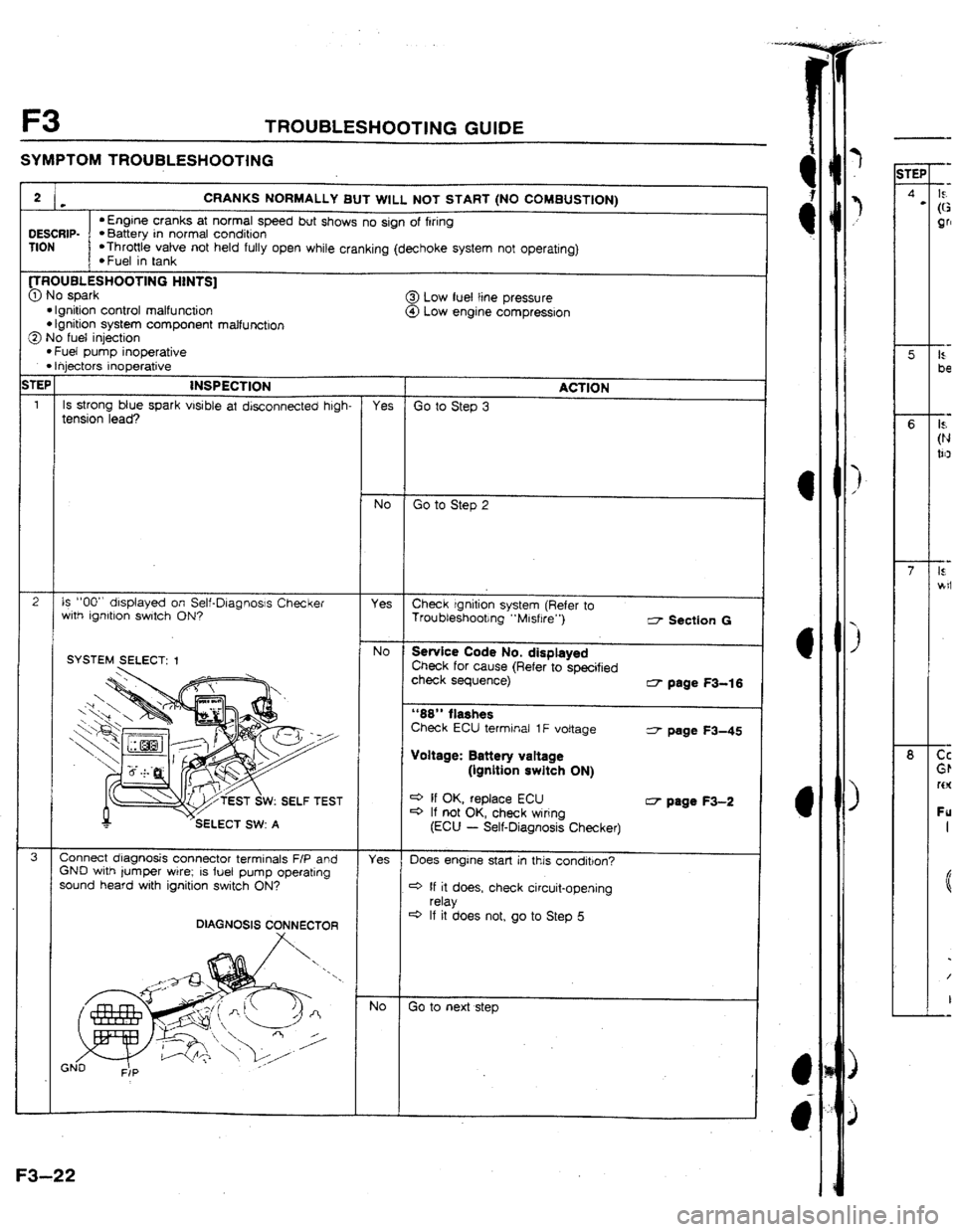
2 . CRANKS NORMALLY BUT WILL NOT START (NO COMBUSTION)
LIESCRIP-
l Engine cranks at normal speed but shows no sign of firing l Battery in normal condition
TION *Throttle valve not held fufly open while cranking (dechoke system not operating}
l Fuel in tank
UROOBLESHUOTlNG HINTS]
@ No spark
@.I low fuei tine pressure
l Ignition control malfunction @I Low engine compresslon l Ignition system component malfunction
@ No fuel injection
l Fuel pump inoperative l Ihjectors inoperative
;TEP
INSPECTION
I ACTION
1
Is strong btue spark visible at disconnected high- Yes Go to Step 3
tension lead?
NO Go to Step 2
2 Is “00” dlsplayed on Self-Dlagnosjs Checker
Yes
with ignltron switch ON? Check rgnltion system (Refer to
Troubleshooting “Misfire”)
c7 Section G
SYSTEM SELECT: 1 No
Service Code No. displayed Check for cause (Refer to specified
check sequence)
G- page
F3-16
“66” flashes
Check ECU termrnal 1F voltage
3 page W-45
Voltage: Battery vabage
(ignition switch ON)
W: SELF TEST C+ If OK, replace ECU
4 If not OK, check wiring
CT page F3-2
(ECU
- Self-Diagnosis Checker)
3
Connect diagnosis connector terminals F/P and
Yes
GND with jumper wire; IS fuel pump operating Does engine start in this condition?
sound heard wjth ignition switch ON?
4 If it does, check circuit-opening
relay
4 If it does not, go to Step 5
No Go to next step
F3-22
iTEF
6
8