torque MAZDA 323 1992 Workshop Manual Suplement
[x] Cancel search | Manufacturer: MAZDA, Model Year: 1992, Model line: 323, Model: MAZDA 323 1992Pages: 279, PDF Size: 24.15 MB
Page 6 of 279

3
3
,
>
1.
3
>
>
HOW TO USE THIS MANUAL GI
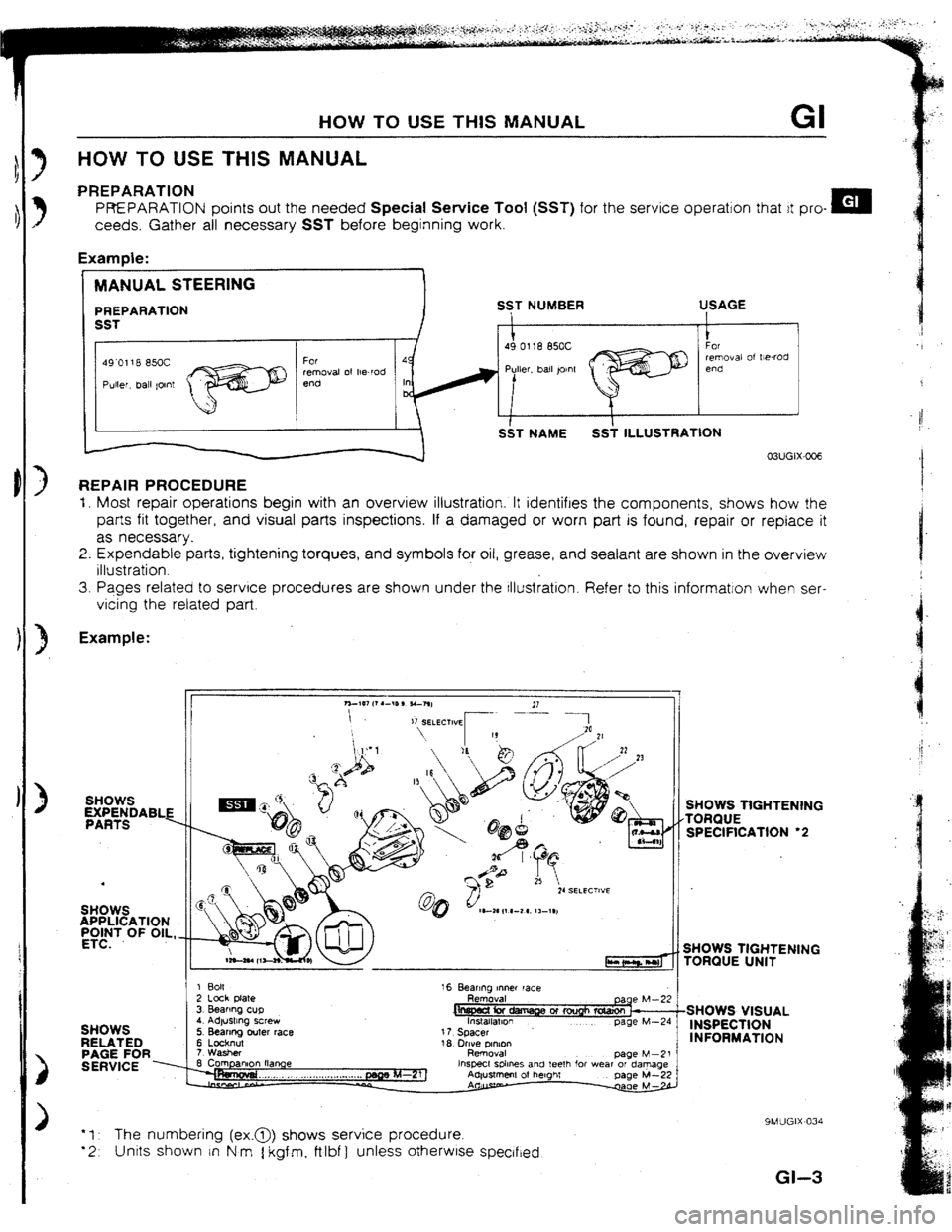
HOW TO USE THIS MANUAL
PREPARATION
PREPARATION points out the needed Special Service Tool (SST) for the service operation that it pro- m
ceeds. Gather all necessary SST before beginning work.
Examde:
MANUAL STEERING
PREPARATlON
SST
49’0118 85oC
Puller, ball tolnt For
removal of he-rod
end SST NUMBER
1
49 0118 85oC USAGE
1
For
removal of Wrod
end
S&T NAME SS; ILLUSTRATlON
REPAIR PROCEDURE
I. Most repair operations begin with an overview illustration. It identifies the components, shows how the
parts fit together, and visual parts inspections. If a damaged or worn part is found, repair or replace it
as necessary.
2. Expendable parts, tightening torques, and symbols for oil, grease, and sealant are shown in the overview
illustration.
3. Pages related to service procedures are shown under the tllustration. Refer to this informatron when ser-
vicing the related part
Example:
SHOWS
yA;ytDABLE
.
SHOWS
APPLICATION
;v’dT OF OlL, _
SH
RE
2
3ws .ATED
3E FOR
?VICE . 1 Bolt
2 Lock Nate
3 Bearmg cup
4 Adtustmg screw
5 Bearing outer race
6 Locknut
7 Washer 16 Beanno Inner race
Rem&al
17 Spacer page M-24
18 lhve olnion
Daoe M-21
hspect sphes and teeIh for wear ordaqge SHOWS TIGHTENING
TORQUE
SPECIFICATION
l 2
SHOWS TIGHTENING
TORQUE UNIT
:
SHOWS VISUAL
INSPECTION
INFORMATION
9MlJGIX~034
*I The numbering (ex.@> shows service procedure.
l 2 Unrts shown in N m 1 kgf m, ftlbf ] unless otherwlse speclfted
Gl-3
Page 9 of 279

GI FUNDAMENTAL PROCEDURES
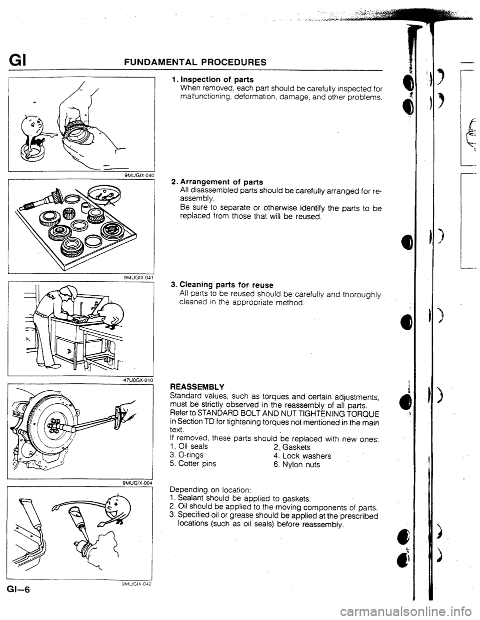
I. Inspection of parts
When removed, each part should be carefully inspected for
malfunctioning, deformation, damage, and other problems.
2. Arrangement of parts
All disassembled parts should be carefully
arranged for re-
assembly.
Be sure to separate or otherwise identify the parts to be
replaced from those that will be reused.
3. Cteaning parts for reuse
All parts to be reused should be carefully and thoroughly
cleaned in the appropriate method.
Gl-6
9MUGIX-042
REASSEMBtY
Standard values, such as torques and certain adjustments,
must be
strictly observed in the reassembly of all parts.
Refer to STANDARD BOLT AND NUT TIGHTENING TORQUE
in Section TD for tightening torques not mentioned in the main
text.
tf removed, these parts should be replaced with new ones:
1. Oil seals
2, Gaskets
3. O-r.ings
4. Lock washers
.
5. Cotter pins
6. Nylon nuts
Depending on location:
1. Sealant should be applied to gaskets.
2. Oil should be applied
to the moving components of parts.
3. Specified oil or grease should be applied at the prescribed
locations (such as oil seals) before reassembty.
Page 15 of 279

GI IDENTIFICATION NUMBER tOCATlONS/UNlTS/ABBREVIATlONS
IDENTIFICATION NUMBER LOCATIONS
VEHICLE tDENTtRCATtUN NUM8ER (VIM) ENGINE MODEL AND NUMBER
I
UNITS
N.rn { kgf m or kgfcm,
f-t&f or tn.lbf 1 . . . . . . . . . . . . . . . . Torque
rpm ._ . . . Revolutions per minute
A.. ,_...___.... Ampere(s)
v I... Volt(s)
$2 . .._..__......_.....__... Ohm(s) (resls‘tance)
kPa { kgflcm*, psr] . . . . . . . Pressure
{usually positive)
mmHg I inl-lg ] . . . . . . . . . Pressure
(usually negatrve)
W . . . ._ .._.__ .._ . . . . . . ..,......... Watt
titers [US qt, Imp qt 1 . V&me
mm { rn 1 . . . . . . . . . . . . . . . . . . . . . . . Length
89UOGX-006
ABBREWATIONS
ABDC _. . . . . . . . . . . After bottom dead
center
A/C . . . . . . . ._.. _. . . . . . . . . Air conditioner
ACC .__ . . . . . . . Accessones
ATX .._ ._ . . . . . . . . . . . . . . Automate transaxle
ATDC _.. __ _. . . . . After top dead center
ATF ,... ._....__._.. Automatic transmission
fluid
BAC ._ . . . . . . . . . . . . . . ,. Bypass air control
BBDC _. . . . . . . . . . . . . .._. Before bottom dead
center
BTDC ., ._._... . . . Before top dead center
CPU . . . . . . . . . Central processrng unit EC-AT
........................... Electronrcally-controlled
automatic transmlsslon
ECU ._ ....................... Engine control unit
EG 1 ..................... Electronc gasoll ne
injectron
E/L. ............................ Electrrcal load
EX .............................. Exhaust
IC ................................ Integrated clrcult
IGN ........................... lgnrtlon
IN ..... ........................ Intake
INT
............................... Intermittent
ISC ............................ Idle speed control
U-l ................................
Left hand
M..
........................... Motor
MIL
........ ...................... MatfunctIon Indicator
iamp
MTX. ........................... Manual transaxle
00.. .............................. Overdnve
Of F .............................. Swrtch off
ON
............................... Switch
on
PCV .............................. Positive crankcase
ventilation
PRC .......................... Pressure regulator
control
P/S ............................. Power steerrng
P/W ............................
Power window
RH ............................... Rlght hand
SST
............................. Special service tool
ST.. ............................... Starl
SW.. ............................. Switch
TDC. ............................ Top dead center
4WD .............................
4-wheel drive
03UGIX-802
INS7
If a t’
and
Whe
1, II-!
2. II-!
3. E-
4. Dr
W-1 2
Page 43 of 279

F3 TURBOCHARGERCONTROL
TURBOCHARGERCONTROL
OUTLINE
l The-capacity of the air-to-air intercooler is increased to reduce the intake air temperature and to the tm-
prove engine performance.
l With addition of the improved wastegate control system, the engine’s high rpm torque is increased.
TURBOCHARG
INTERCOOLER
SYSTEM DIAGRAM
WASTEGATE SOLENOrD VALVE
F3-10
Page 98 of 279

M FRONT AXLE
WHEEL HUB, STEERING KNUCKLE
RemovaI / Inspection I Installation
1. Remove in the order shown in the figure, referring to Removal Note.
2. Inspect all parts and repair or replace as necessary.
3. InstaH in the reverse order of removal, referring to Installation Note.
Caution
l Loosely tighten the shock absorber bolts. Lower the vehicle and tighten the bolts to the specified
torque with the vehicle unladen.
4. Adjust the front wheel alianment.
16-22 ]1.6-2.3, 12-161 I
19.0-l 2.0, 65-86.7 I
1. Wheel hub nut
2. Wheel and tire
3. Locknut
Removal Note . . . . . . .._.. . . . . . . . . . . . . . . . . . . . page M-7
installation Note .I.........,..,............ page M-7
4. Brake caliper assembly
Service . _. . . . . . . . . ,__. . . , , . ._. _. , , . . . , . ._ ._. . . . . . Section P
5. Disc plate
lnspectioti .~~*.......*~...,......,,,.....*~...~. Section P
6. ABS wheel speed sensor (if equipped)
7. Tie rod end
Removal Note . . . . . . .._.......... I . .._.....= page M-7
lnstallatiofi Note . . .._... _.__......,....... page M-7
M-6
8. Lower ball joint
9. Steering knuckle, wheel hub, and dust cover
Inspect-wheel hub for cracks and damage
Inspect knuckle spindle for cracks and
damage
Inspect dust cuver for damage and dis-
tortion
Disassembly I Inspection I
Assembly . ..C1..............~...,.....,.....
page M-8
Page 99 of 279

FRONT AXLE M
13EOMX308
13EOMX-310
1
13EOMX-311
Removal note
Locknut
Caution
l Do not damage the drive shaft.
l Do not reuse the locknut.
1.
Raise the staked portion of the locknut using a chisel.
2. Lock the
hub by applying the brakes.
3. Remove the locknut.
Tie rod end
Caution i
l Do not damage the dust boot.
t
Losen the nut and disconnect the tie rod end bv using the
I
SST.
P
Installation note
Tie rod end
Caution
l Do not damage the dust boot.
tnstall the nut and secure it with the new cotter
Tightening torque:
43-56 N-m (4.3-5.8 kgf,m, 31-41 ft-lbf
Locknut
lnstail a new
locknut and stake it, as shown. pin.
Tightening torque: 236-318 N-m
f 24.0-32.5 kgfm, 174-235 ftelbf ]
M-7.
Page 104 of 279

REAR AXLE
WHEEL HUB, KNUCKLE
Removal I Inspection / installation
1. Remove in the order shown in the figure, referring to
Removal Note. 2. Inspect all parts and repair or replace as necessary.
3. Install in the reverse order of removal, referring to Installation Note.
Caution
l Loosely tighten the shock absorber bolts. Lower the vehicle and tighten the bolts to the specified
torque with the vehicle unladen.
4. Adiust the rear wheel alianment.
16-22 1?.6-2.3, 12-16 I
7
IO.o-13.0,
66-66.7 1 1. Wheel and tire
2. Locknut
Removal Note..; . . . . . . . . , . . . . ,.......- -.. page M-f 3
Installation Note .._...,.,...._.__........ page M-13
I$ Brake caliper assembly
Service . . . . . . . . . . . ..e......._......... ,.,...,....
Section P
4. Disc plate
‘Service ..I....................__....... . . . . . . . . . Section P 5. Af3S wheel speed sensor (if equipped)
6. Wheel hub, knuckle
Disassembly I Inspect& /
Assem bty . . . . . . . ..I..........*..*.*...-... page M-14
Inspect wheel hub and knuckle for damage
or cracks
Inspect dust cover for damage or defor-
mation
M-12
Page 105 of 279

REAR AXLE M
Removal note
Locknut
Caution
l Do not damage the drive shaft.
l Do not reuse the locknut.
I. Raise the staked portion of the tocknut using a chisel.
2. Lock the hub by applying the brakes.
3. Remove the locknut.
1 13EOMX-308
13EOMX-327 installation note
Locknut
Install a new locknut and stake it, as shown.
Tightening torque: 236-318 N-m
[ 24.0-32.5 kgfm, f 74-235 ftelbf
‘I
Page 120 of 279

CONVENTIONAL BRAKE SYSTEM P
WlfH ABS
1 f3EOPX-3 I 7
I* 44 44’
/
13EOPX-318
MASTER CYLINDER PRESSURE kPa f kgffcm2, psi 1
16AOPX-m 0
PRUPORTIONING VALVE
Inspection
1. Connect the SST to the brake pipes with adapters as shown
in the figure.
Adapter and flare nut tightening torque:
12.8-21.5 Nsm f 130-220 kgfcm, I 134 90 inlbf 1
Note
l Disconnect and connect the brake pipes with SST.
2. Bleed the air from the brake system.
3. Depress the brake pedal until the master cylinder pressure
equals A; then record rear brake pressure A’.
4. Depress the brake pedal again, apply additional pressure
until the pressure equals B; then record pressure B’.
Fluid pressure
kPa { kgVcm2, psi]
A
A’ 8
8’
WITHOUT 1960
1960
ABS 120, 284 (20,284] 5880
1 al96 12, 28)
(60, 853) 2750 (28, 3881
*I96 12,281
WITH ABS $;;4 1960 f 20,284) 5880
1 *196 12,261 160, 853 3140 {32, 455)
1
*294 [3,42)
-,
--.
. p-g.’
Page 124 of 279

CONVENTIONAL BRAKE SYSTEM P
13EOPX-324
I %EOPX-071
Disassembly note
Piston
Caution
l Blow the compressed air slowly to prevent the pis-
ton from popping out.
I. Place a piece of wood in the caliper.
2. Blow compressed air through the pipe hole to force the pis-
ton out of the caLper.
Piston seal
Remove the piston seal from the caliper by using the SST.
I
Bleeder screw
Loosen the bleeder screw by using the SST.
Assembly note
Bleeder screw
Tightening the bteeder screw by using the SST.
Tightening torque:
5.9-8.8 Nom (60-90 kgfcm, 53-78 in&f ]