check oil MAZDA 6 2002 Suplement User Guide
[x] Cancel search | Manufacturer: MAZDA, Model Year: 2002, Model line: 6, Model: MAZDA 6 2002Pages: 909, PDF Size: 17.16 MB
Page 191 of 909
INTAKE-AIR SYSTEM
F2–39
F2
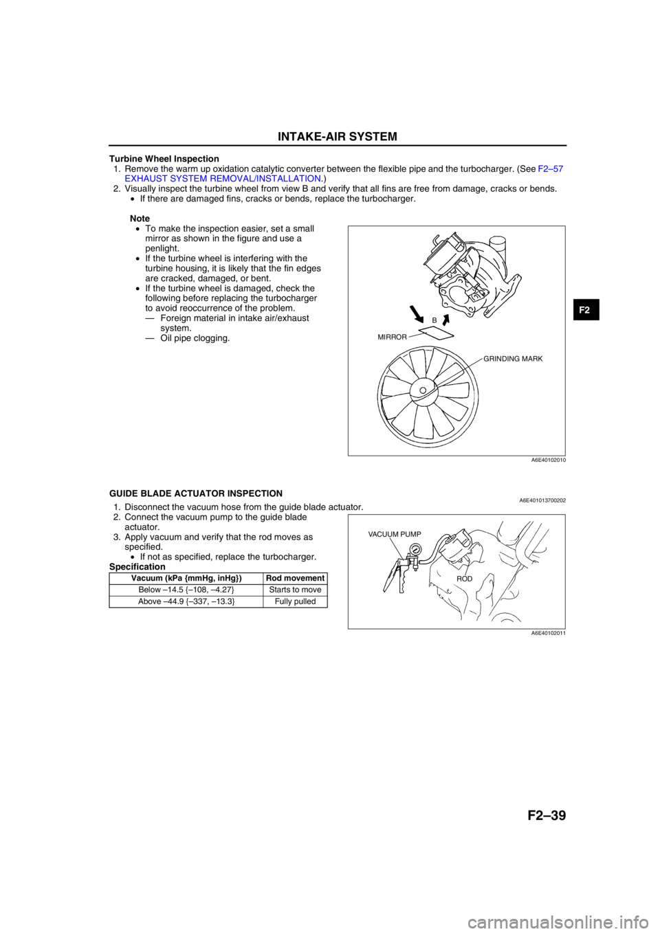
Turbine Wheel Inspection
1. Remove the warm up oxidation catalytic converter between the flexible pipe and the turbocharger. (See F2–57
EXHAUST SYSTEM REMOVAL/INSTALLATION.)
2. Visually inspect the turbine wheel from view B and verify that all fins are free from damage, cracks or bends.
•If there are damaged fins, cracks or bends, replace the turbocharger.
Note
•To make the inspection easier, set a small
mirror as shown in the figure and use a
penlight.
•If the turbine wheel is interfering with the
turbine housing, it is likely that the fin edges
are cracked, damaged, or bent.
•If the turbine wheel is damaged, check the
following before replacing the turbocharger
to avoid reoccurrence of the problem.
—Foreign material in intake air/exhaust
system.
—Oil pipe clogging.
End Of Sie
GUIDE BLADE ACTUATOR INSPECTIONA6E4010137002021. Disconnect the vacuum hose from the guide blade actuator.
2. Connect the vacuum pump to the guide blade
actuator.
3. Apply vacuum and verify that the rod moves as
specified.
•If not as specified, replace the turbocharger.
Specification
End Of Sie
MIRRORB
GRINDING MARK
A6E40102010
Vacuum (kPa {mmHg, inHg}) Rod movement
Below –14.5 {–108, –4.27} Starts to move
Above –44.9 {–337, –13.3} Fully pulled
VACUUM PUMP
ROD
A6E40102011
Page 201 of 909
FUEL SYSTEM
F2–49
F2
(2) Apply a slight amount of clean engine oil to
the sealing surface of the fuel pump unit.
(3) Align the fuel pipe on the fuel pump unit and
quick release connector so that the tabs of the
retainer are correctly fitted into the quick
release connector. Push the quick release
connector straight into the retainer until a click
is heard.
(4) Lightly pull and push the quick release
connector a few times by hand and verify that
it can move 2.0—3.0 mm {0.08—0.11 in} and
it is connected securely.
•If the quick release connector does not
move at all, verify that O-ring is not
damaged of that is has not slipped, and reconnect the quick release connector.
2. When the retainer is removed, perform the following procedure.
End Of Sie
FUEL TANK INSPECTIONA6E401242110202
Caution
•Disconnecting/connecting the quick release connector without cleaning it may possibly cause
damage to the fuel pipe and quick release connector. Always clean the quick release connector
joint area before disconnecting/connecting using a cloth or soft brush, and make sure that it is
free of foreign material.
Note
•This inspection is for two rollover valves and check valve (two-way) integrated in the fuel tank.
1. Remove the fuel tank with the fuel gauge sender unit. (See F2–45 FUEL TANK REMOVAL/INSTALLATION.)
2. Plug the fuel pipe of the fuel gauge sender unit.
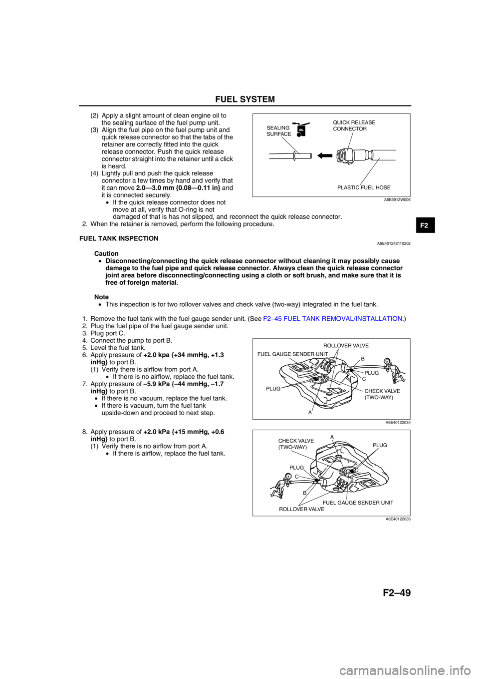
3. Plug port C.
4. Connect the pump to port B.
5. Level the fuel tank.
6. Apply pressure of +2.0 kpa {+34 mmHg, +1.3
inHg} to port B.
(1) Verify there is airflow from port A.
•If there is no airflow, replace the fuel tank.
7. Apply pressure of –5.9 kPa {–44 mmHg, –1.7
inHg} to port B.
•If there is no vacuum, replace the fuel tank.
•If there is vacuum, turn the fuel tank
upside-down and proceed to next step.
8. Apply pressure of +2.0 kPa {+15 mmHg, +0.6
inHg} to port B.
(1) Verify there is no airflow from port A.
•If there is airflow, replace the fuel tank.
End Of Sie
OILOIL
PLASTIC FUEL HOSE QUICK RELEASE
CONNECTOR SEALING
SURFACE
A6E3912W006
B
C
APLUG
PLUG
CHECK VALVE
(TWO-WAY)
FUEL GAUGE SENDER UNIT
ROLLOVER VALVE
A6E40122034
B CA
PLUGPLUG
CHECK VALVE
(TWO-WAY)
FUEL GAUGE SENDER UNIT
ROLLOVER VALVE
A6E40122035
Page 369 of 909

TROUBLESHOOTING
F2–217
F2
NO.21 ENGINE NOISEA6E408018881223
Diagnostic Procedure
21 ENGINE NOISE
DESCRIPTION•Engine noise under hood.
POSSIBLE
CAUSE•Engine internal damage
•Timing belt displacement
•Fuel injector malfunction
•Loose attaching bolts or worn parts
•Improper drive belt tension
•Air leakage from intake-air system
•Incorrect injection timing
•Erratic signal from CKP sensor
•Erratic signal from CMP sensor
•Fuel pressure sensor or related circuit malfunction
•Boost sensor or related circuit malfunction
•Accelerator position sensor or related circuit malfunction
•MAF/IAT sensor or related circuit malfunction
•ECT sensor or related circuit malfunction
•EGR system or malfunction
•IAT sensor No.2 or related circuit malfunction
•Vacuum leakage
•Suction control valve malfunction (built-in supply pump)
•Air leakage from intake-air system
•Air in power steering fluid line
•Turbocharger operating noise
•Solenoid valve operating noise
Warning
The following troubleshooting flow chart contains the fuel system diagnosis and repair
procedures. Read the following warnings before performing the fuel system services:
•Fuel vapor is hazardous. It can easily ignite, causing serious injury and damage. Always keep
sparks and flames away from fuel.
•Fuel line spills and leakage are dangerous. Fuel can ignite and cause serious injury or death
and damage. Fuel can also irritate skin and eyes. To prevent this, always complete “BEFORE
REPAIR PROCEDURE” and “AFTER REPAIR PROCEDURE” described in this manual.
Note
•PCM checks fuel injection amount during a set interval while idling, and automatically corrects it to
maintain engine efficiency. It is normal that engine noise and vibration might be a little louder during
this process.
STEP INSPECTION RESULTS ACTION
1 Is squeal, click or chirp sound present? Yes Inspect engine oil level, solenoid valves installation or
drive belt.
No Go to next step.
2 Is rumble or grind sound present? Yes Inspect drive belt tension or power steering system
fluid level.
If okay, perform power steering fluid line air bleed.
No Go to next step.
3 Is rattle sound present? Yes Inspect location of rattle for loose parts.
No Go to next step.
4 Is hiss sound present? Yes Inspect for vacuum leakage and intake-air system
leakage.
No Go to next step.
5 Is rap or roar sound present? Yes Inspect exhaust system or loose parts.
No Go to next step.
Page 457 of 909
K2–42
AUTOMATIC TRANSAXLE
CENTRIFUGAL BALANCE CLUTCH DESCRIPTIONA6E571401030208Function
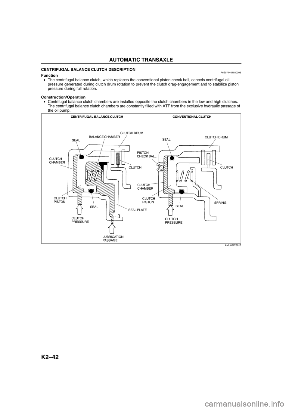
•The centrifugal balance clutch, which replaces the conventional piston check ball, cancels centrifugal oil
pressure generated during clutch drum rotation to prevent the clutch drag-engagement and to stabilize piston
pressure during full rotation.
Construction/Operation
•Centrifugal balance clutch chambers are installed opposite the clutch chambers in the low and high clutches.
The centrifugal balance clutch chambers are constantly filled with ATF from the exclusive hydraulic passage of
the oil pump.
AMU0517S018
Page 494 of 909
AUTOMATIC TRANSAXLE
K2–79
K2
Automatic Transaxle Fluid (ATF) Level Inspection
Caution
•The ATF amount varies according to ATF's temperature. Therefore, when checking the ATF level or
replacing the ATF, use a thermometer to measure the temperature then adjust the ATF amount to
the specified level according to the specified temperature.
1. Park the vehicle on level ground.
2. Apply the parking brake and position wheel chocks securely to prevent the vehicle from rolling.
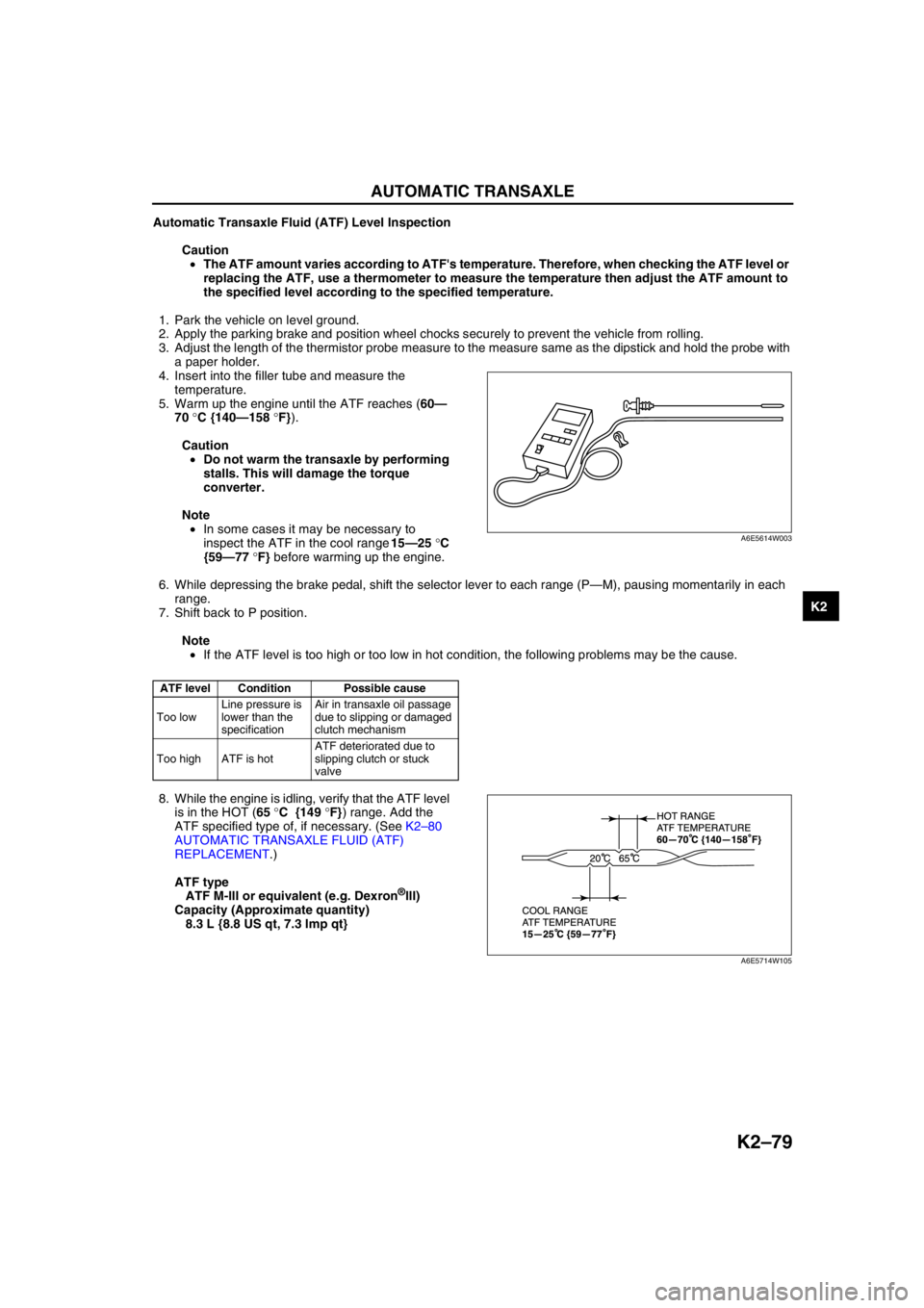
3. Adjust the length of the thermistor probe measure to the measure same as the dipstick and hold the probe with
a paper holder.
4. Insert into the filler tube and measure the
temperature.
5. Warm up the engine until the ATF reaches (60—
70 °C {140—158 °F}).
Caution
•Do not warm the transaxle by performing
stalls. This will damage the torque
converter.
Note
•In some cases it may be necessary to
inspect the ATF in the cool range 15—25 °C
{59—77 °F} before warming up the engine.
6. While depressing the brake pedal, shift the selector lever to each range (P—M), pausing momentarily in each
range.
7. Shift back to P position.
Note
•If the ATF level is too high or too low in hot condition, the following problems may be the cause.
8. While the engine is idling, verify that the ATF level
is in the HOT (65 °C {149 °F}) range. Add the
ATF specified type of, if necessary. (See K2–80
AUTOMATIC TRANSAXLE FLUID (ATF)
REPLACEMENT.)
ATF type
ATF M-III or equivalent (e.g. Dexron
®III)
Capacity (Approximate quantity)
8.3 L {8.8 US qt, 7.3 Imp qt}
End Of Sie
ATF level Condition Possible cause
Too lowLine pressure is
lower than the
specificationAir in transaxle oil passage
due to slipping or damaged
clutch mechanism
Too high ATF is hotATF deteriorated due to
slipping clutch or stuck
valve
A6E5614W003
A6E5714W105
Page 557 of 909

K2–142
ON-BOARD DIAGNOSTIC
End Of SieDTC P0740A6E577018901212
Diagnostic procedure
12VERIFY TROUBLESHOOTING OF DTC P0720
COMPLETED
•Make sure to reconnect all disconnected
connectors.
•Clear DTC from memory using WDS or
equivalent.
•Drive vehicle with vehicle speed 40 km/h {25
mph} or above for 2 second or more
•Is same DTC present?Yes Replace TCM, then go to next step.
(See K2–96 TCM REMOVAL/INSTALLATION.)
No Go to next step.
13VERIFY AFTER REPAIR PROCEDURE
•Perform “After Repair Procedure”.
(See K2–124 AFTER REPAIR PROCEDURE.)
•Is there any DTC present?Yes Go to applicable DTC inspection.
No Troubleshooting completed. STEP INSPECTION ACTION
DTC P0740 TCC system malfunction
DETECTION
CONDITION•RPM difference between crankshaft (engine speed signal) and reverse clutch drum (input/turbine speed
sensor signal) exceeds the pre-programmed value.
Diagnostic support note:
•This is continuous monitor (CCM).
•MIL illuminates if TCM detects the above malfunction conditions in two consecutive drive cycles.
•PENDING CODE is available.
•FREEZE FRAME DATA is available.
•AT warning light does not indication.
•DTC is stored in TCM memory.
POSSIBLE
CAUSE•ATF level low.
•Deteriorated ATF.
•TCC solenoid valve and pressure control solenoid stuck.
•Line pressure low.
•Oil pump malfunction.
•Control valve stuck
•Torque convert clutch malfunction
•TCM malfunction.
STEP INSPECTION ACTION
1VERIFY FREEZE FRAME DATA HAS BEEN
RECORDED
•Has FREEZE FRAME PID DATA been
recorded?Yes Go to next step.
No Record FREEZE FRAME PID DATA on repair order, then
go to next step.
2VERIFY RELATED REPAIR INFORMATION
AVAILABILITY
•Check for related Service Bulletins and/or on-
line repair information availability.
•Is any related repair information available?Yes Perform repair or diagnosis according to available repair
information.
•If vehicle is not repaired, go to next step.
No Go to next step.
3CHECK ATF CONDITION
•Turn ignition key to OFF.
•Check ATF condition.
—Clear red: Normal
—Milky: Water mixed in fluid
—Reddish brown: Deteriorated ATF
•Is it okay?
(See K2–78 Automatic Transaxle Fluid (ATF)
Condition Inspection.)Yes Go to next step.
No If ATF color milky or reddish brown, replace ATF, then go to
Step 5.
(See K2–80 AUTOMATIC TRANSAXLE FLUID (ATF)
REPLACEMENT.)
4CHECK ATF LEVEL
•Start engine.
•Warm up ATX.
•Is ATF level within specification?
(See K2–79 Automatic Transaxle Fluid (ATF)
Level Inspection.)Yes Go to next step.
No Adjust ATF level, then go to Step 9.
(See K2–79 Automatic Transaxle Fluid (ATF) Level
Inspection.)
Page 646 of 909
M–16
ELECTRONIC 4WD CONTROL SYSTEM
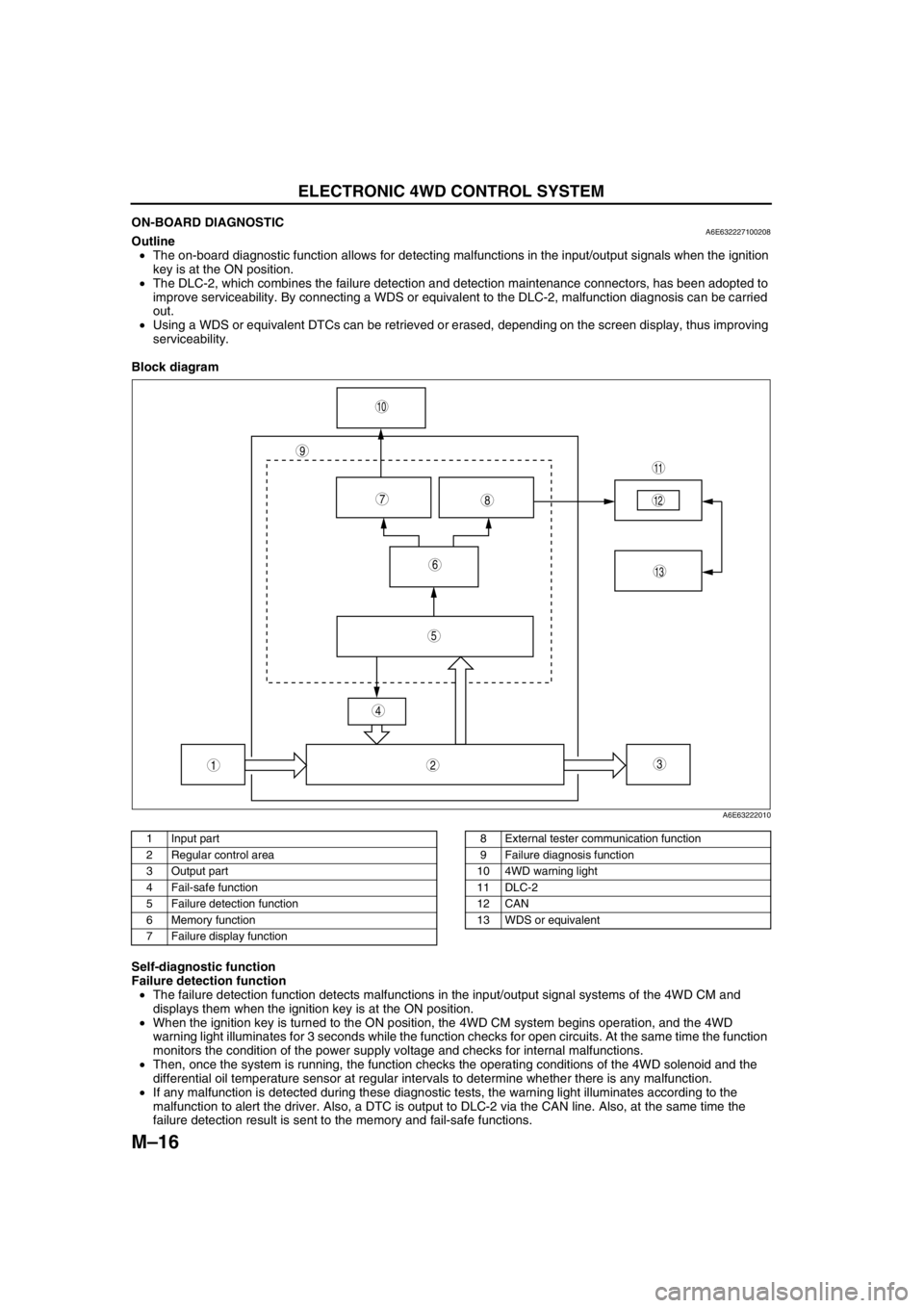
ON-BOARD DIAGNOSTICA6E632227100208Outline
•The on-board diagnostic function allows for detecting malfunctions in the input/output signals when the ignition
key is at the ON position.
•The DLC-2, which combines the failure detection and detection maintenance connectors, has been adopted to
improve serviceability. By connecting a WDS or equivalent to the DLC-2, malfunction diagnosis can be carried
out.
•Using a WDS or equivalent DTCs can be retrieved or erased, depending on the screen display, thus improving
serviceability.
Block diagram
.
Self-diagnostic function
Failure detection function
•The failure detection function detects malfunctions in the input/output signal systems of the 4WD CM and
displays them when the ignition key is at the ON position.
•When the ignition key is turned to the ON position, the 4WD CM system begins operation, and the 4WD
warning light illuminates for 3 seconds while the function checks for open circuits. At the same time the function
monitors the condition of the power supply voltage and checks for internal malfunctions.
•Then, once the system is running, the function checks the operating conditions of the 4WD solenoid and the
differential oil temperature sensor at regular intervals to determine whether there is any malfunction.
•If any malfunction is detected during these diagnostic tests, the warning light illuminates according to the
malfunction to alert the driver. Also, a DTC is output to DLC-2 via the CAN line. Also, at the same time the
failure detection result is sent to the memory and fail-safe functions.
9
87
5
4
3
10
13
11
12
6
12
A6E63222010
1 Input part
2 Regular control area
3 Output part
4 Fail-safe function
5 Failure detection function
6 Memory function
7 Failure display function8 External tester communication function
9 Failure diagnosis function
10 4WD warning light
11 DLC-2
12 CAN
13 WDS or equivalent
Page 745 of 909
P–12
CONVENTIONAL BRAKE SYSTEM
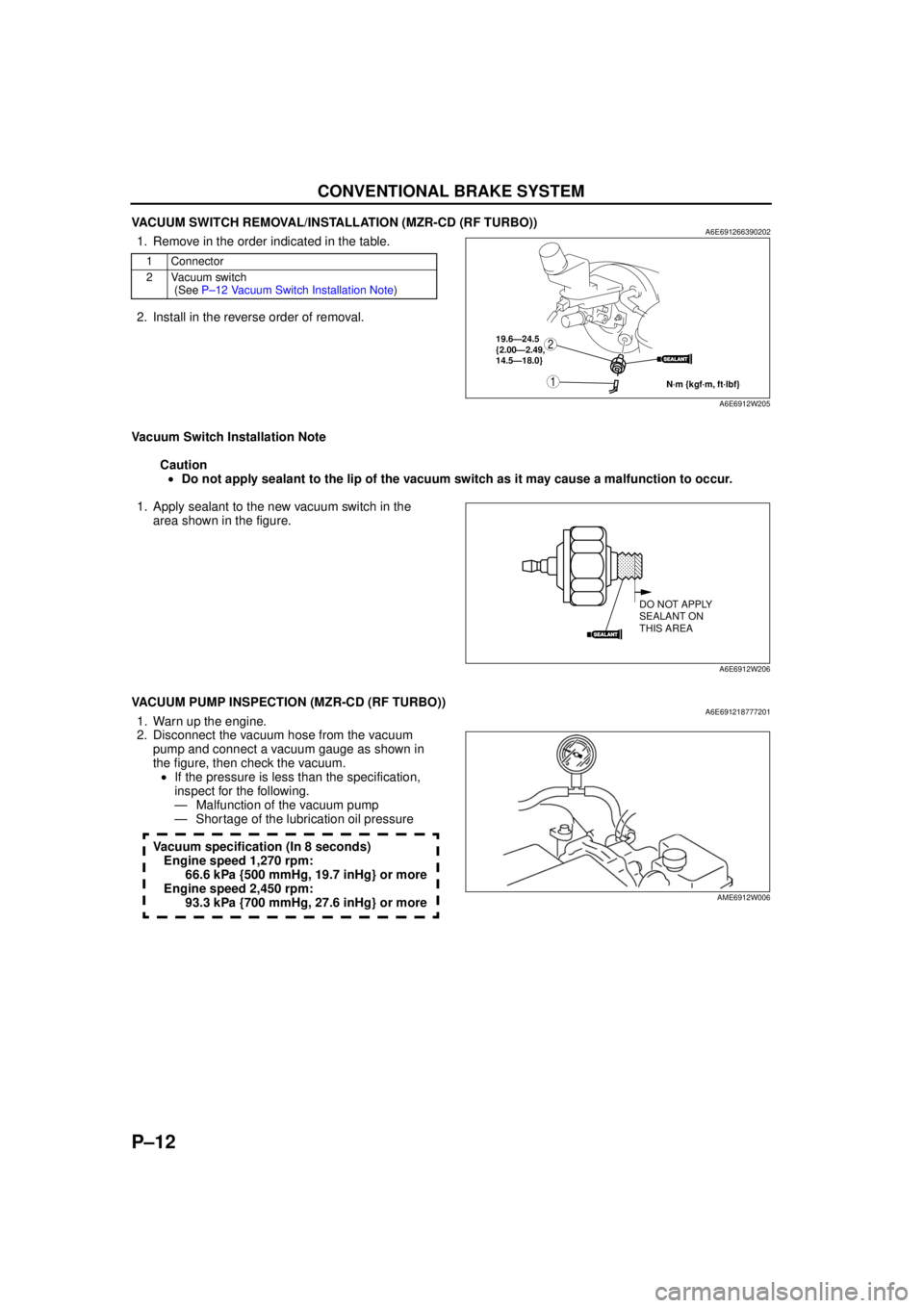
VACUUM SWITCH REMOVAL/INSTALLATION (MZR-CD (RF TURBO))A6E6912663902021. Remove in the order indicated in the table.
2. Install in the reverse order of removal.
Vacuum Switch Installation Note Caution• Do not apply sealant to the lip of the vacuum switch as it may cause a malfunction to occur.
1. Apply sealant to the new vacuum switch in the area shown in the figure.
End Of Sie
VACUUM PUMP INSPECTION (MZR-CD (RF TURBO))A6E6912187772011. Warn up the engine.
2. Disconnect the vacuum hose from the vacuum pump and connect a vacuum gauge as shown in
the figure, then check the vacuum.• If the pressure is less than the specification,
inspect for the following.
— Malfunction of the vacuum pump
— Shortage of the lubrication oil pressure
Vacuum specification (In 8 seconds) Engine speed 1,270 rpm: 66.6 kPa {500 mmHg, 19.7 inHg} or more
Engine speed 2,450 rpm: 93.3 kPa {700 mmHg, 27.6 inHg} or more
End Of Sie
1 Connector
2 Vacuum switch (See P –12 Vacu um S w itch Ins tal lat ion Note )
SEALANT
1
219.6—24.5
{2.00—2.49,
14.5—18.0}
N·m {kgf·m, ft·lbf}
A6E6912W205
SEALANT
DO NOT APPLY
SEALANT ON
THIS AREA
A6E6912W206
AME6912W006
Page 767 of 909
REAR SUSPENSION
R–5
R
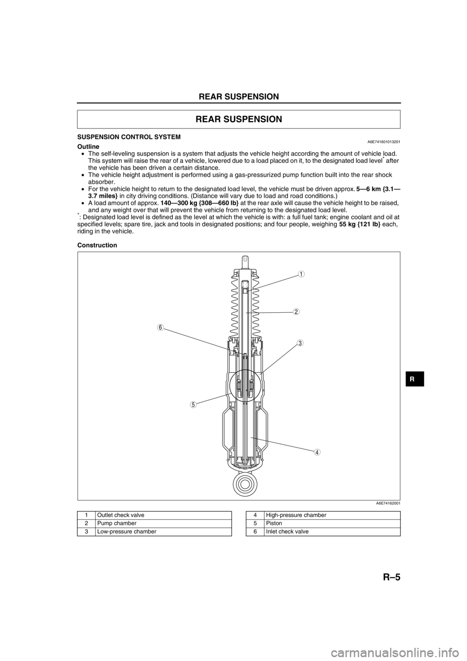
SUSPENSION CONTROL SYSTEMA6E741601013201Outline
•The self-leveling suspension is a system that adjusts the vehicle height according the amount of vehicle load.
This system will raise the rear of a vehicle, lowered due to a load placed on it, to the designated load level
* after
the vehicle has been driven a certain distance.
•The vehicle height adjustment is performed using a gas-pressurized pump function built into the rear shock
absorber.
•For the vehicle height to return to the designated load level, the vehicle must be driven approx. 5—6 km {3.1—
3.7 miles} in city driving conditions. (Distance will vary due to load and road conditions.)
•A load amount of approx. 140—300 kg {308—660 lb} at the rear axle will cause the vehicle height to be raised,
and any weight over that will prevent the vehicle from returning to the designated load level.
*: Designated load level is defined as the level at which the vehicle is with: a full fuel tank; engine coolant and oil at
specified levels; spare tire, jack and tools in designated positions; and four people, weighing 55 kg {121 lb} each,
riding in the vehicle.
Construction
.
REAR SUSPENSION
5
4
3
6
1
2
A6E74162001
1 Outlet check valve
2 Pump chamber
3 Low-pressure chamber4 High-pressure chamber
5Piston
6 Inlet check valve
Page 768 of 909
R–6
REAR SUSPENSION
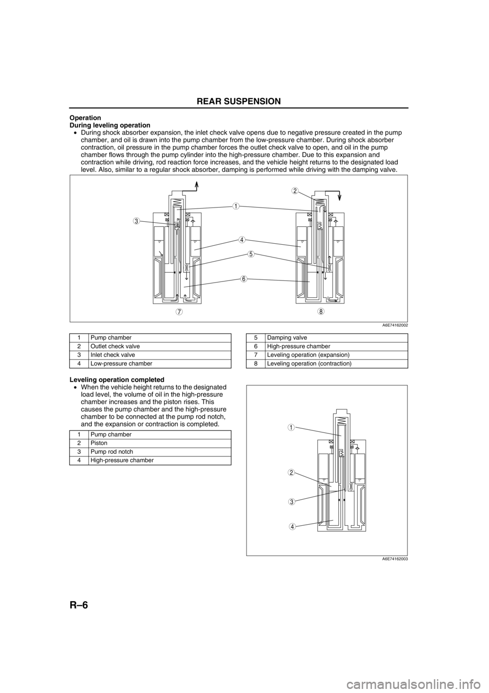
Operation
During leveling operation
•During shock absorber expansion, the inlet check valve opens due to negative pressure created in the pump
chamber, and oil is drawn into the pump chamber from the low-pressure chamber. During shock absorber
contraction, oil pressure in the pump chamber forces the outlet check valve to open, and oil in the pump
chamber flows through the pump cylinder into the high-pressure chamber. Due to this expansion and
contraction while driving, rod reaction force increases, and the vehicle height returns to the designated load
level. Also, similar to a regular shock absorber, damping is performed while driving with the damping valve.
.
Leveling operation completed
•When the vehicle height returns to the designated
load level, the volume of oil in the high-pressure
chamber increases and the piston rises. This
causes the pump chamber and the high-pressure
chamber to be connected at the pump rod notch,
and the expansion or contraction is completed.
.
87
5
4
3
6
1
2
A6E74162002
1 Pump chamber
2 Outlet check valve
3 Inlet check valve
4 Low-pressure chamber5 Damping valve
6 High-pressure chamber
7 Leveling operation (expansion)
8 Leveling operation (contraction)
1 Pump chamber
2Piston
3 Pump rod notch
4 High-pressure chamber
4
3
1
2
A6E74162003