brake rotor MAZDA 6 2002 Workshop Manual Suplement
[x] Cancel search | Manufacturer: MAZDA, Model Year: 2002, Model line: 6, Model: MAZDA 6 2002Pages: 909, PDF Size: 17.16 MB
Page 736 of 909

OUTLINE
P–3
P
STRUCTURAL VIEWA6E690201020204
.
End Of Sie
7
53
1
2
6
7
53
6
89
4
4
8
10
15
14
15
14
12
13
13
12
11
11
16
16
A6E6902W201
1L.H.D.
2 R.H.D.
3 Brake pedal
4 Master cylinder
5 Power brake unit
6 Front brake (disc)
7 Rear brake (disc)
8 Vacuum pump9 Without ABS
10 Dual proportioning valve
11 ABS (ABS/TCS) or DSC HU/CM
12 ABS wheel-speed sensor (front)
13 ABS sensor rotor (front)
14 ABS wheel-speed sensor (rear)
15 ABS sensor rotor (rear)
16 Combine sensor
Page 737 of 909

P–4
ABS/TCS
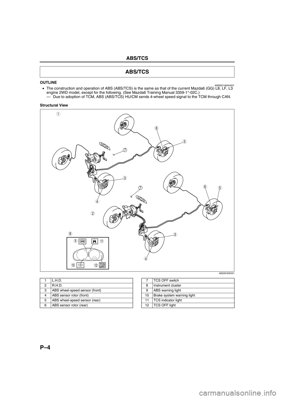
OUTLINEA6E692146444201•The construction and operation of ABS (ABS/TCS) is the same as that of the current Mazda6 (GG) L8, LF, L3
engine 2WD model, except for the following. (See Mazda6 Training Manual 3359-1*-02C.)
—Due to adoption of TCM, ABS (ABS/TCS) HU/CM sends 4-wheel speed signal to the TCM through CAN.
Structural View
.
ABS/TCS
5
3
1
2
6
7
5
3
6
8
4
4
7
9
10TCS
OFF
11
12
A6E6916W201
1 L.H.D.
2 R.H.D.
3 ABS wheel-speed sensor (front)
4 ABS sensor rotor (front)
5 ABS wheel-speed sensor (rear)
6 ABS sensor rotor (rear)7 TCS OFF switch
8 Instrument cluster
9 ABS warning light
10 Brake system warning light
11 TCS indicator light
12 TCS OFF light
Page 739 of 909

P–6
DYNAMIC STABILITY CONTROL
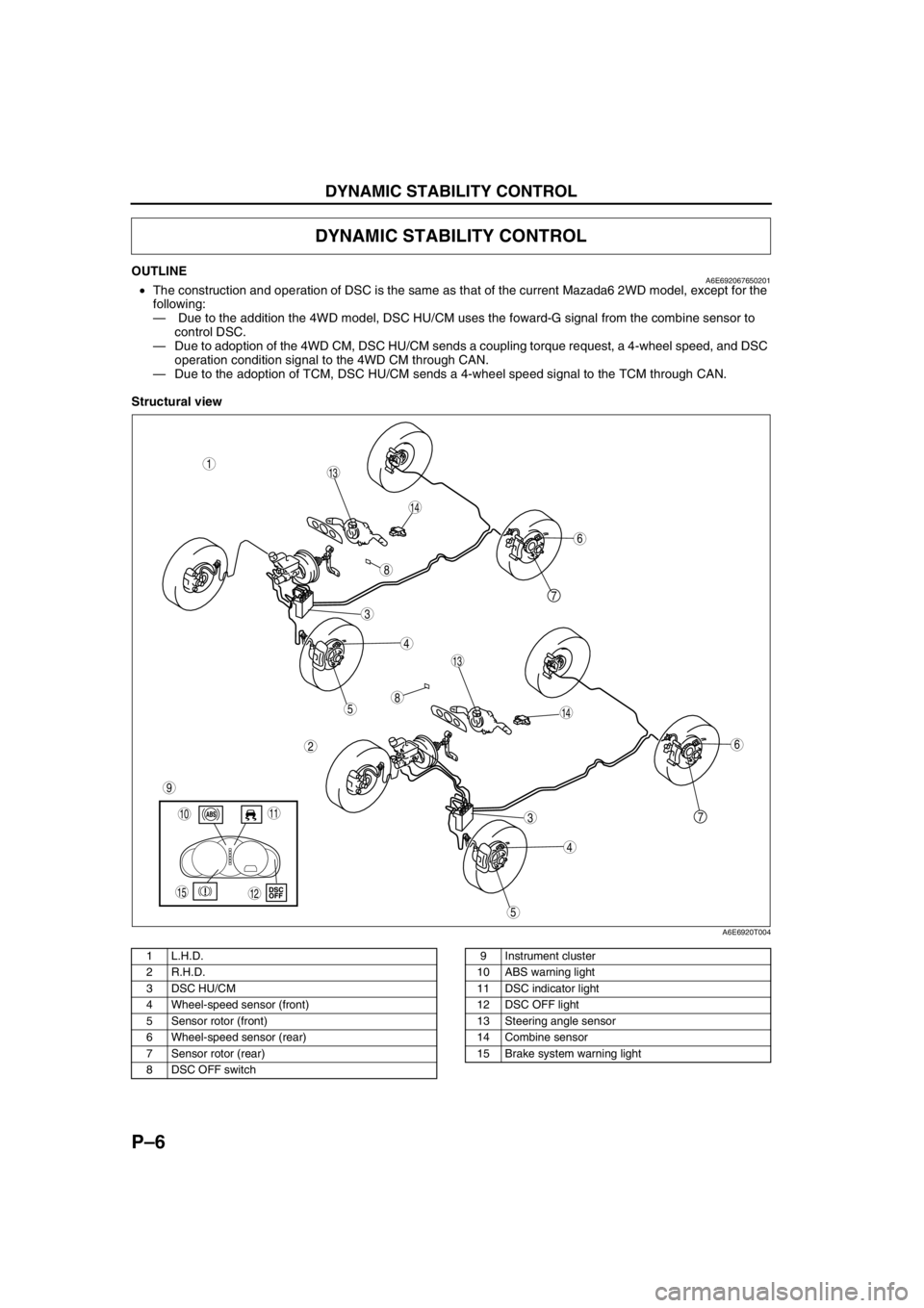
OUTLINEA6E692067650201•The construction and operation of DSC is the same as that of the current Mazada6 2WD model, except for the
following:
— Due to the addition the 4WD model, DSC HU/CM uses the foward-G signal from the combine sensor to
control DSC.
—Due to adoption of the 4WD CM, DSC HU/CM sends a coupling torque request, a 4-wheel speed, and DSC
operation condition signal to the 4WD CM through CAN.
—Due to the adoption of TCM, DSC HU/CM sends a 4-wheel speed signal to the TCM through CAN.
Structural view
.
DYNAMIC STABILITY CONTROL
7
5
4
3
1
2
14
13
6
13
12
5
4
3
7
6
1011
9
14
8
8
15
A6E6920T004
1 L.H.D.
2 R.H.D.
3 DSC HU/CM
4 Wheel-speed sensor (front)
5 Sensor rotor (front)
6 Wheel-speed sensor (rear)
7 Sensor rotor (rear)
8 DSC OFF switch9 Instrument cluster
10 ABS warning light
11 DSC indicator light
12 DSC OFF light
13 Steering angle sensor
14 Combine sensor
15 Brake system warning light
Page 754 of 909

ON-BOARD DIAGNOSTIC
P–21
P
DSC ON-BOARD DIAGNOSISA6E697067650201DTC Table
Note
•There is no change except for the code marked with an asterisk *
ON-BOARD DIAGNOSTIC
DTC
Diagnosis system component
WDS or
equivalent
B1318 DSC power supply
B1342 DSC HU/CM
B1483 Stop switch signal (with DSC only)
B1484 Stop switch signal (with DSC only)
B1486 Stop switch signal (with DSC only)
B1627 Reverse signal (with DSC only)
B2477 Module configuration (with DSC only)
C1095 Motor relay, pump motor
C1096 Motor relay, pump motor
C1119* Engine control system
C1125 Brake fluid level sensor (with DSC only)
C1140 DSC HU (pump) (with DSC only)
C1145 Right front wheel-speed sensor
C1148 Right front wheel-speed sensor/sensor rotor
C1155 Left front wheel-speed sensor
C1158 Left front wheel-speed sensor/sensor rotor
C1165 Right rear wheel-speed sensor
C1168 Right rear wheel-speed sensor/sensor rotor
C1175 Left rear wheel-speed sensor
C1178 Left rear wheel-speed sensor/sensor rotor
C1186 Fail-safe relay
C1194 Left front pressure reduction solenoid valve
C1198 Left front pressure retention solenoid valve
C1210 Right front pressure reduction solenoid valve
C1214 Right front pressure retention solenoid valve
C1233 Left front wheel-speed sensor/sensor rotor
C1234 Right front wheel-speed sensor/sensor rotor
C1235 Right rear wheel-speed sensor/sensor rotor
C1236 Left rear wheel-speed sensor/sensor rotor
C1242 Left rear pressure reduction solenoid valve
C1246 Right rear pressure reduction solenoid valve
C1250 Left rear pressure retention solenoid valve
C1254 Right rear ABS pressure retention solenoid valve
C1266 Fail-safe relay
C1280 Combine sensor (with DSC only)
C1400 Right front traction switch solenoid valve (with DSC only)
C1410 Left front traction switch solenoid valve (with DSC only)
C1414 DSC HU/CM (with DSC only)
C1507 DSC control (with DSC only)
C1508 TCS control
C1510 Right front solenoid valve, motor or wheel-speed sensor/sensor rotor
C1511 Left front solenoid valve, motor or wheel-speed sensor/sensor rotor
C1512 Right rear solenoid valve, motor or wheel-speed sensor/sensor rotor
C1513 Left rear solenoid valve, motor or wheel-speed sensor/sensor rotor
Page 757 of 909

P–24
ON-BOARD DIAGNOSTIC
ABSRF_I
(Right front ABS pressure
retention solenoid valve output
state)ON/OFF•During ABS control: ON/
OFF
(solenoid valve is activated/
deactivated)
•Not ABS control: OFF
(solenoid valve is
deactivated)Internal fault of ABS
(ABS/TCS) or DSC
HU/CM. Replace ABS
(ABS/TCS) or DSC
HU/CM.—
ABSLF_I
(Left front ABS pressure
retention solenoid valve output
state)ON/OFF•During ABS control: ON/
OFF
(solenoid valve is activated/
deactivated)
•Not ABS control: OFF
(solenoid valve is
deactivated)Internal fault of ABS
(ABS/TCS) or DSC
HU/CM. Replace ABS
(ABS/TCS) or DSC
HU/CM.—
ABSVLVRLY
(Fail-safe relay output state)ON/OFF•Fail-safe relay is
activated: ON
•Fail-safe relay is
deactivated: OFFInspect ABS (ABS/
TCS) or DSC HU/CM.
—
ABSPMPRLY
(Motor relay output state)ON/OFF•Motor relay is activated: ON
•Motor relay is deactivated:
OFFInspect ABS (ABS/
TCS) or DSC HU/CM.—
SWA POS (with DSC only)
(Steering angle sensor input)ANGLE•Steering wheel is in neutral
position: 0 DEG
•Steering wheel is turned to
left: Changes between
0 DEG and -1,638.40 DEG
•Steering wheel is turned to
right: Changes between
0 DEG and 1,638.35 DEGInspect steering angle
sensor.
R, U, W, X
LF_WSPD
(Left front wheel-speed sensor
input)SPEED•Vehicle is stopped: 0 KPH
{0 MPH}
•Vehicle is driving: Indicates
vehicle speedInspect wheel-speed
sensor/sensor rotor.ABS (ABS/
TCS): E, I
DSC: F, J
RF_WSPD
(Right front wheel-speed
sensor input)SPEED•Vehicle is stopped: 0 KPH
{0 MPH}
•Vehicle is driving: Indicates
vehicle speedInspect wheel-speed
sensor/sensor rotor.ABS (ABS/
TCS): D, G
DSC: I, M
LR_WSPD
(Left rear wheel-speed sensor
input)SPEED•Vehicle is stopped: 0 KPH
{0 MPH}
•Vehicle is driving: Indicates
vehicle speedInspect wheel-speed
sensor/sensor rotor.ABS (ABS/
TCS): C, F
DSC: N, Q
RR_WSPD
(Right rear wheel-speed
sensor input)SPEED•Vehicle is stopped: 0 KPH
{0 MPH}
•Vehicle is driving: Indicates
vehicle speedInspect wheel-speed
sensor/sensor rotor.ABS (ABS/
TCS): A, B
DSC: H, K
LAT ACC (with DSC only)
(Lateral-G sensor input)ACCELERATION•Vehicle is stopped or driving
straight: 0 G
•Cornering to left: Changes
between 0 G and 1.27 G
•Cornering to right: Changes
between 0 G and -1.28 GInspect ABS wheel-
speed sensor/sensor
rotor.
O
YAW_RATE (with DSC only)
(Yaw rate sensor input)ACCELERATION•Vehicle is stopped or driving
straight: 0 DG/S
•Cornering to left: Changes
between 0 DG/S and 127
DG/S
•Cornering to right: Changes
between 0 DG/S and -128
DG/SInspect combine
sensor.
T
MCYLI P (with DSC only)
(Brake fluid pressure sensor
input)PRESSURE•Brake pedal is released:
0 MPa
•Brake pedal is depressed:
Changes between 0 MPa
and 25.5 MPaInspect DSC HU/CM.
— PID Name
(Definition)Unit/Condition Condition/Specification ActionABS (ABS/
TCS) HU/CM or
DSC HU/CM
terminal