ignition MAZDA 6 2002 Suplement User Guide
[x] Cancel search | Manufacturer: MAZDA, Model Year: 2002, Model line: 6, Model: MAZDA 6 2002Pages: 909, PDF Size: 17.16 MB
Page 26 of 909

B1–4
OUTLINE, ENGINE
SUPPLEMENTAL SERVICE INFORMATIONA6E220202000205•The following changes and/or additions have been made since publication of the Mazda6 Workshop Manual
(1730-1*-02C).
Engine
•Removal/Installation procedure for 4WD has been adopted.
End Of Sie
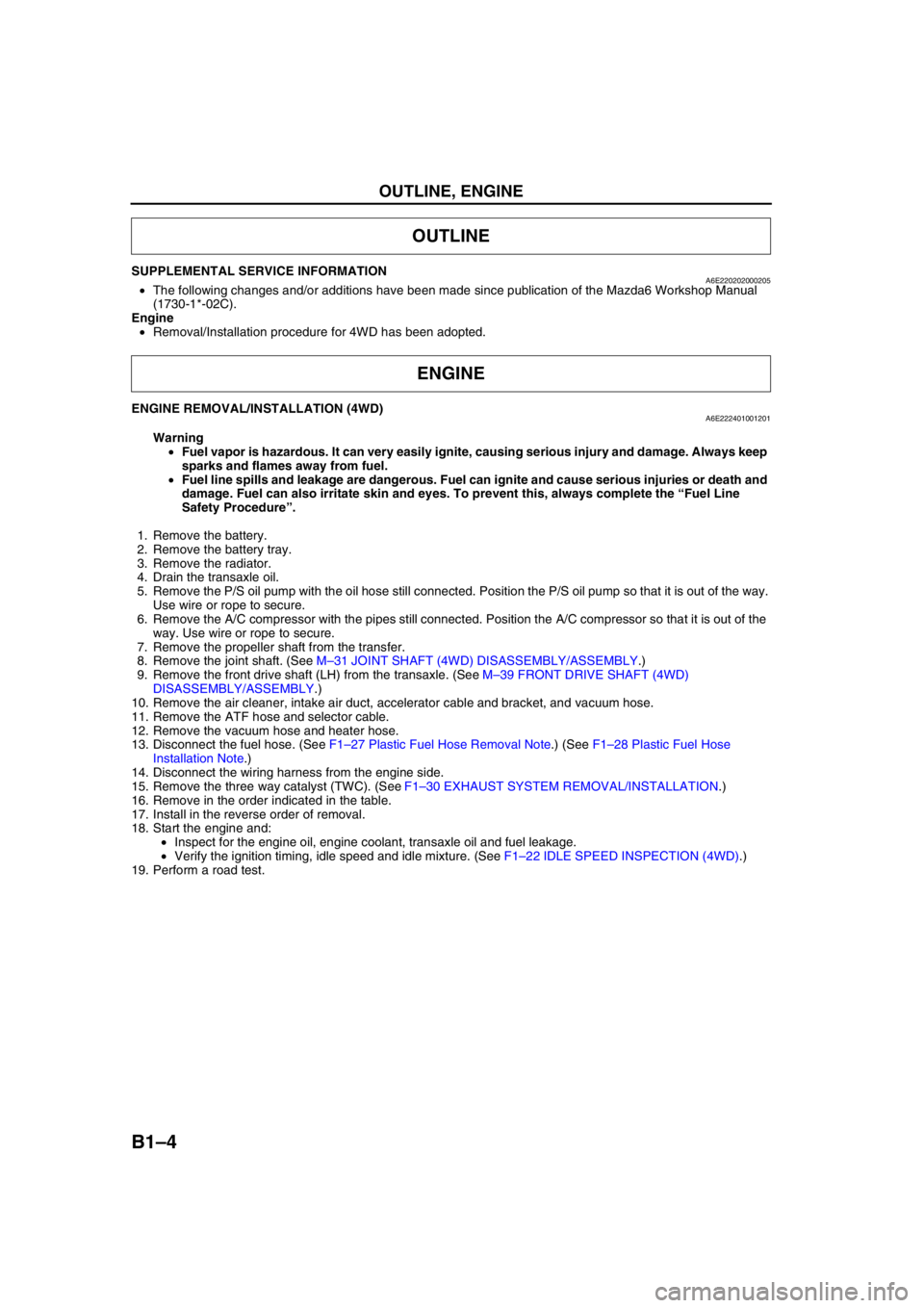
ENGINE REMOVAL/INSTALLATION (4WD)A6E222401001201
Warning
•Fuel vapor is hazardous. It can very easily ignite, causing serious injury and damage. Always keep
sparks and flames away from fuel.
•Fuel line spills and leakage are dangerous. Fuel can ignite and cause serious injuries or death and
damage. Fuel can also irritate skin and eyes. To prevent this, always complete the “Fuel Line
Safety Procedure”.
1. Remove the battery.
2. Remove the battery tray.
3. Remove the radiator.
4. Drain the transaxle oil.
5. Remove the P/S oil pump with the oil hose still connected. Position the P/S oil pump so that it is out of the way.
Use wire or rope to secure.
6. Remove the A/C compressor with the pipes still connected. Position the A/C compressor so that it is out of the
way. Use wire or rope to secure.
7. Remove the propeller shaft from the transfer.
8. Remove the joint shaft. (See M–31 JOINT SHAFT (4WD) DISASSEMBLY/ASSEMBLY.)
9. Remove the front drive shaft (LH) from the transaxle. (See M–39 FRONT DRIVE SHAFT (4WD)
DISASSEMBLY/ASSEMBLY.)
10. Remove the air cleaner, intake air duct, accelerator cable and bracket, and vacuum hose.
11. Remove the ATF hose and selector cable.
12. Remove the vacuum hose and heater hose.
13. Disconnect the fuel hose. (See F1–27 Plastic Fuel Hose Removal Note.) (See F1–28 Plastic Fuel Hose
Installation Note.)
14. Disconnect the wiring harness from the engine side.
15. Remove the three way catalyst (TWC). (See F1–30 EXHAUST SYSTEM REMOVAL/INSTALLATION.)
16. Remove in the order indicated in the table.
17. Install in the reverse order of removal.
18. Start the engine and:
•Inspect for the engine oil, engine coolant, transaxle oil and fuel leakage.
•Verify the ignition timing, idle speed and idle mixture. (See F1–22 IDLE SPEED INSPECTION (4WD).)
19. Perform a road test.
OUTLINE
ENGINE
Page 91 of 909

OUTLINE
F1–3
F1
CONTROL SYSTEM DIAGRAM (4WD)A6E390218881204
.
* : Equipped for L3 engine modelEnd Of Sie
9
8
7
54
3
10
19
18
17
15
16
14
13
11
12
20
29
28
27
25
26
24
23
21
22
30
3938
3735
33
36
31
32
40
6
1
2
3441
A6E39022000
1PCM
2 Ignition coil
3 Generator
4* VAD shutter valve
5 Air cleaner
6 MAF sensor
7* VAD shutter valve actuator
8* VAD control solenoid valve
9* Vacuum chamber
10* VAD check valve (one-way)
11 IAC valve
12 Purge solenoid valve
13 TP sensor
14 MAP sensor
15* VIS control solenoid valve
16 Variable tumble control solenoid valve
17* VIS shutter valve actuator
18* VIS shutter valve
19 VTCS shutter valve actuator
20 VTCS shutter valve
21 Fuel injector22* OCV
23 CMP sensor
24 EGR valve
25 Knock sensor
26 ECT sensor
27 PCV valve
28 CKP sensor
29 HO2S (front)
30 HO2S (rear)
31 Charcoal canister
32 Check valve (two-way)
33 Pressure regulator
34 Fuel filter (high-pressure)
35 Fuel pump
36 Fuel filter (low-pressure)
37 Fuel tank
38 Rollover valve
39 Pulsation damper
40 Fuel pump (transfer)
41 To PCM
Page 93 of 909

OUTLINE
F1–5
F1
11 Knock sensor
12 CKP sensor
13 CMP sensor
14 Fuel injector No.1
15 Fuel injector No.2
16 Fuel injector No.3
17 Fuel injector No.4
18 IAC valve
19 Oxygen sensor heater (front)
20 Oxygen sensor heater (rear)
21 A/C relay22 Cooling fan relay
23 Cooling fan relay
24 Cooling fan relay
25 TR switch
26 Fuel pump relay
27 Coil
28 Security light
29 Ignition switch
30 Main relay
31 TR switch
32 Starter relay
Page 94 of 909

F1–6
OUTLINE
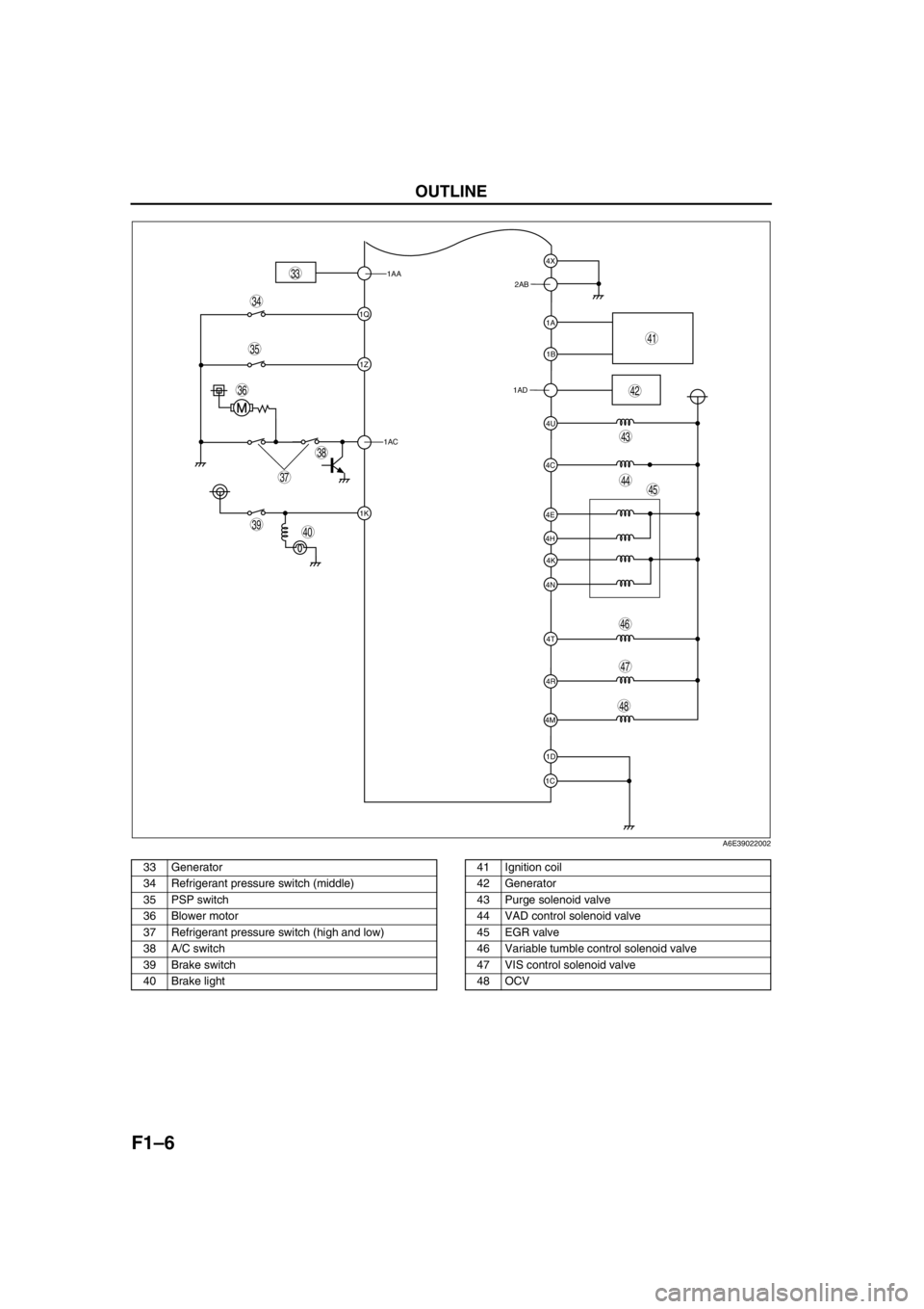
.
1AA
1Q
1Z
1AC
1K
1C1D 4M4R 4N4K 4H4E
4T 4C4U 1AD1B 1A 2AB4X
39
38
37
35
36
33
40
45
46
44
43
41
42
34
48
47
A6E39022002
33 Generator
34 Refrigerant pressure switch (middle)
35 PSP switch
36 Blower motor
37 Refrigerant pressure switch (high and low)
38 A/C switch
39 Brake switch
40 Brake light41 Ignition coil
42 Generator
43 Purge solenoid valve
44 VAD control solenoid valve
45 EGR valve
46 Variable tumble control solenoid valve
47 VIS control solenoid valve
48 OCV
Page 96 of 909

F1–8
OUTLINE
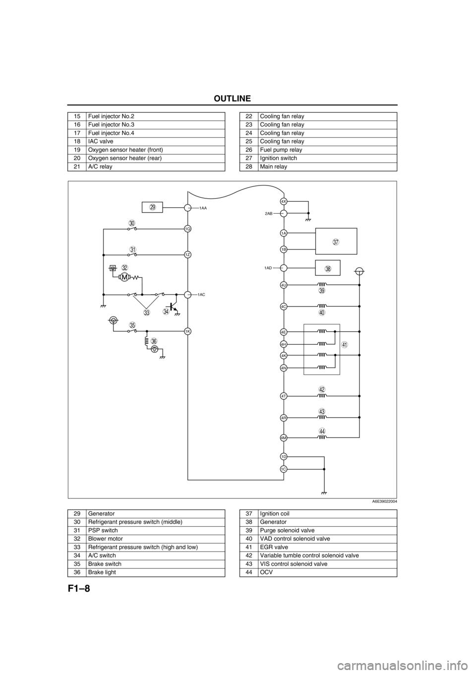
.
15 Fuel injector No.2
16 Fuel injector No.3
17 Fuel injector No.4
18 IAC valve
19 Oxygen sensor heater (front)
20 Oxygen sensor heater (rear)
21 A/C relay22 Cooling fan relay
23 Cooling fan relay
24 Cooling fan relay
25 Cooling fan relay
26 Fuel pump relay
27 Ignition switch
28 Main relay
1AA
1Q
1Z
1AC
1K
1C1D 4M4R 4N4K 4H4E
4T 4C4U 1AD1B 1A 2AB4X
39
38
37
35
36
33
31
32
40
44
43
41
42
34
29
30
A6E39022004
29 Generator
30 Refrigerant pressure switch (middle)
31 PSP switch
32 Blower motor
33 Refrigerant pressure switch (high and low)
34 A/C switch
35 Brake switch
36 Brake light37 Ignition coil
38 Generator
39 Purge solenoid valve
40 VAD control solenoid valve
41 EGR valve
42 Variable tumble control solenoid valve
43 VIS control solenoid valve
44 OCV
Page 103 of 909

CONTROL SYSTEM
F1–15
F1
Output Device
×:Applied
—: Not applied
* : For L3 engine only
End Of Sie
Item SignalMazda6 (GG, GY)
Remark for new model
4WD ATX Unleaded
(RON 90
or above)Current
model
IAC valve IAC×Same as current model
VIC solenoid valve* VIC×—×Same as current model
Variable tumble control
solenoid valveVTCS×Same as current model
Oil control valve (OCV)*Variable valve
timing control×—×Same as current model
Fuel injectorFuel injection
control×Same as current model
Fuel pump relayFuel pump
control×Same as current model
Ignition coil ESA control×Same as current model
EGR valve EGR control×Same as current model
Purge solenoid valve Purge control×Same as current model
BARO factor for Purge control has been
eliminated.
Heated oxygen sensor
heater
(Front, rear)O2S heater
control×Same as current model
Field coil
(Generator terminal D)Generator
control×Same as current model
Cooling fan relayElectric fan
control×Same as current model
A/C relayA/C cut-off
control×Same as current model
Controller area network
(CAN)Information
function×Same as current model
TCM (ATX) information have been
adopted for 4WD ATX model.
Page 104 of 909

F1–16
CONTROL SYSTEM
STRUCTURAL VIEW (4WD)A6E394018880202
.
End Of Sie
9
8
7
5
4
3
10
1817
15
16
14
13
11
12
20
25
24
23
21
22
6
1
2
19
A6E39402000
1 MAF/IAT sensor
2 TP sensor
3 MAP sensor
4 CMP sensor
5 CKP sensor
6 ECT sensor
7 Knock sensor
8 HO2S (front)
9 HO2S (rear)
10 PSP switch
11 Brake switch
12 VAD control solenoid valve
13 IAC valve14 VIC solenoid valve
15 Variable tumble control solenoid valve
16 OCV
17 Fuel injector
18 Ignition coil
19 Purge solenoid valve
20 EGR valve
21 BARO sensor
22 PCM (R.H.D.)
23 TCM (R.H.D)
24 PCM (L.H.D.)
25 TCM (L.H.D)
Page 106 of 909

F1–18
CONTROL SYSTEM
*1: For MTX model
*2: For 2WD ATX model
*3: For L3 engine
End Of Sie
1 MAF/IAT sensor
2 TP sensor
3 MAP sensor
4 CMP sensor
5 CKP sensor
6 ECT sensor
7 Knock sensor
8 HO2S (front, rear)
9 PSP switch
10 Vehicle speedometer sensor
11
Clutch switch*
1
12
Neutral switch*1
13
TR switch*2
14 Brake switch
15 A/C switch
16 Refrigerant pressure switch
17 Generator (terminal P: generation voltage)
18 Battery
19
VAD control solenoid valve*
3
20 IAC valve
21
VIC solenoid valve*
3
22 Variable tumble control solenoid valve
23
OCV*
3
24 Fuel injector
25 Fuel pump relay
26 Ignition coil
27 Purge solenoid valve
28 EGR valve
29 Oxygen sensor heater (front, rear)
30 A/C relay
31 Cooling fan relay
32 Generator (terminal D: field coil)
33
VAD control*
3
34 IAC
35
VIC*
3
36 VTCS
37
Variable valve timing control*
3
38 Fuel injection control
39 Fuel pump control
40 Electronic spark advance (ESA) control
41 Purge control
42 EGR control
43 Oxygen sensor heater control
44 A/C cut-off control
45 Electrical fan control
46 Generator control
Page 108 of 909

F1–20
CONTROL SYSTEM
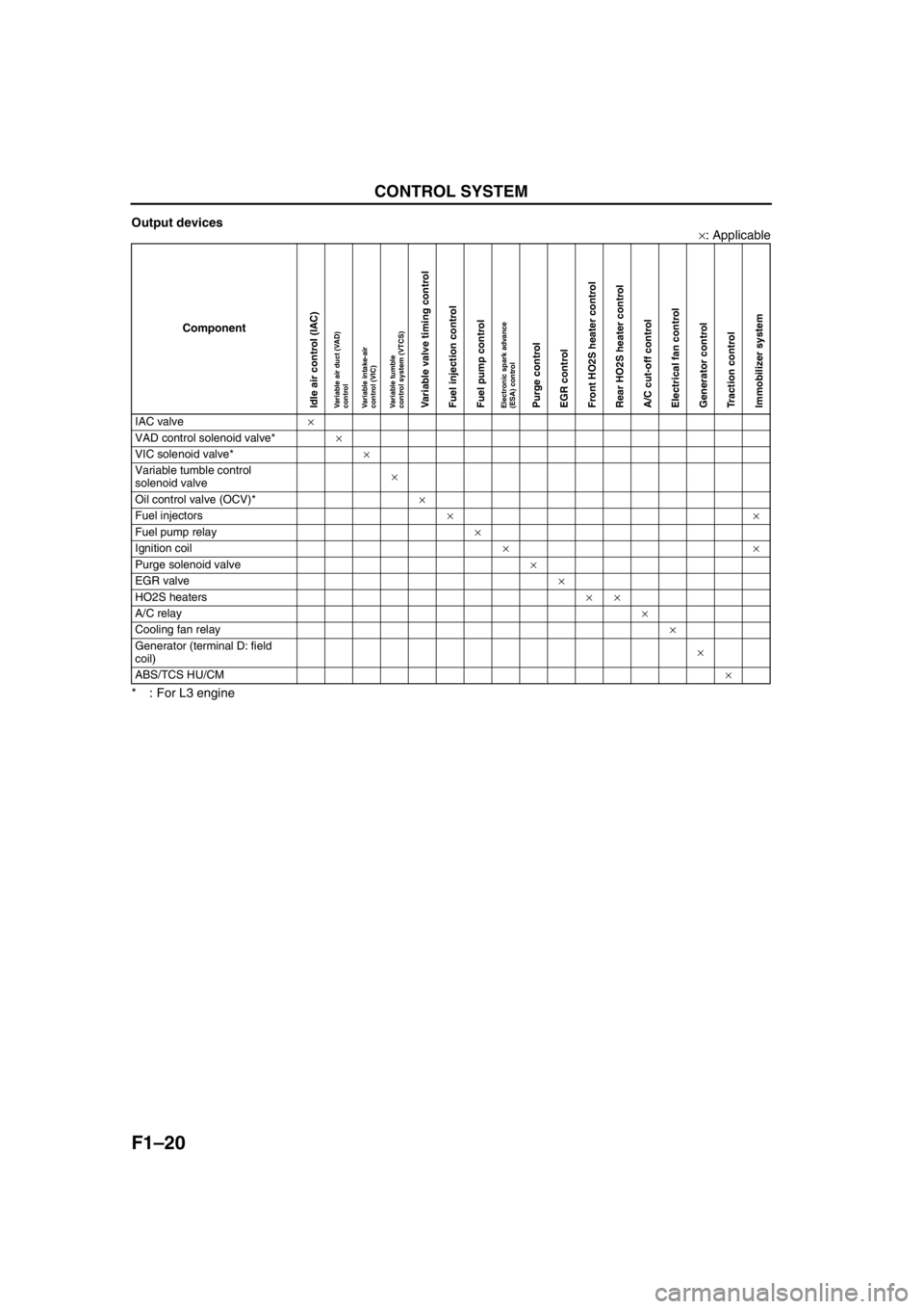
Output devices
×: Applicable
* : For L3 engine
End Of Sie
Component
IAC valve×
VAD control solenoid valve*×
VIC solenoid valve*×
Variable tumble control
solenoid valve×
Oil control valve (OCV)*×
Fuel injectors××
Fuel pump relay×
Ignition coil××
Purge solenoid valve×
EGR valve×
HO2S heaters××
A/C relay×
Cooling fan relay×
Generator (terminal D: field
coil)×
ABS/TCS HU/CM×
Idle air control (IAC)Variable air duct (VAD)
controlVariable intake-air
control (VIC)Variable tumble
control system (VTCS)Variable valve timing controlFuel injection controlFuel pump controlElectronic spark advance
(ESA) controlPurge controlEGR controlFront HO2S heater controlRear HO2S heater controlA/C cut-off controlElectrical fan controlGenerator controlTraction controlImmobilizer system
Page 110 of 909

F1–22
OUTLINE, ENGINE TUNE-UP
SUPPLEMENTAL SERVICE INFORMATIONA6E390218881206•The following changes and/or additions have been made since publication of the Mazda6 Workshop Manual
(1621-10-98E).
Idle speed
•Adjustment procedure has been modified.
Fuel tank
•Removal/installation procedure has been modified.
Fuel pump unit
•Removal/installation procedure has been modified.
Quick release connector (fuel tank side, transfer hose part)
•Removal/installation procedure has been added.
Exhaust system
•Removal/installation procedure has been modified.
PCM
•Inspection procedure has been modified.
On-board diagnostic
•Inspection procedure has been modified.
Troubleshooting
•Inspection procedure has been modified.
End Of Sie
IDLE SPEED INSPECTION (4WD)A6E390802000201
Note
•Ignition timing is not adjustable.
•Ignition timing verification requires WDS or equivalent.
1. Turn off the electrical loads.
2. Warm up the engine as follows.
(1) Start the engine.
(2) Maintain the engine speed at approx. 3,000 rpm until the cooling fans start to operate.
(3) Release the accelerator pedal.
(4) Wait until the cooling fans stop.
3. Verify that the idle speed (WDS: RPM PID) is within the specification using WDS or equivalent.
Idle speed
*1 : Excludes temporary idle speed drop just after the electrical loads are turned on.
*2 : Blower motor is operating at high speed. Headlight switch is turned on. Rear window defroster switch is turned
on. Cooling fans are operating.
End Of Sie
OUTLINE
ENGINE TUNE-UP
Condition
Engine speed (rpm)*1
No load 650—750
Electrical loads*
2 ON650—750
P/S ON 650—750
A/C ON and refrigerant
pressure switch (middle) OFF650—750
A/C ON and refrigerant
pressure switch (middle) ON700—800