maintenance MAZDA 6 2002 Suplement User Guide
[x] Cancel search | Manufacturer: MAZDA, Model Year: 2002, Model line: 6, Model: MAZDA 6 2002Pages: 909, PDF Size: 17.16 MB
Page 20 of 909

GI–16
SCHEDULED MAINTENANCE
Evaporative system (if installed) IIIIIIII
ELECTRICAL SYSTEM
Battery electrolyte level and specific gravity IIIIIIII
All electrical system *5IIIIIIII
CHASSIS AND BODY
Brake lines, hoses and connections IIIIIIII
Brake fluid *3IIIRIIIRIIIRIIIR
Parking brake IIIIIIIIIIIIIIII
Power brake unit and hoses IIIIIIII
Disc brakes IIIIIIIIIIIIIIII
Power steering fluid, lines, hoses, and connections I I I I I I I I I I I I I I I I
Steering operation and linkages IIIIIIII
Manual transaxle oilR
Automatic transaxle fluid level IIIIIIII
Rear differential oil (for 4WD)
*6*7
Transfer oil (for 4WD)
*7
Front and rear suspension and ball joints I I I I
Driveshaft dust boots I I I I
Bolts and nuts on chassis and body TTTTTTTT
Exhaust system and heat shields Inspect every 80,000 km (50,000 miles)
Cabin air filter (if installed) RRRRRRRR
Body condition
(for rust, corrosion and perforation)Inspect annually
Tyres (including spare tyre)
(with inflation pressure adjustment)IIIIIIII Maintenance ItemMaintenance Interval (Number of months or km (miles), whichever comes first)
Months 6 121824303642485460667278849096
×1000 km
10 20 30 40 50 60 70 80 90 100 110 120 130 140 150 160
×1000 miles6.25 12.5 18.75 25 31.25 37.5 43.75 50 56.25 62.5 68.75 75 81.25 87.5 93.75 100
Page 21 of 909

SCHEDULED MAINTENANCE
GI–17
GI
Scheduled Maintenance Service (Specific Work Required)
•The specific work required for each maintenance item is listed in the following table. (Please refer to the section
applicable to the model serviced.)
For Europe (L.H.D. U.K.)
Bold frames: New item
Maintenance Item Specific Work Required
ENGINE
Engine valve clearance Measure clearance
Drive beltsInspect for wear, cracks and fraying, and check tension.
Replace drive belt.
Engine timing belt Replace engine timing belt.
Engine oil Replace engine oil and inspect for leakage.
Oil filter Replace oil filter and inspect for leakage.
COOLING SYSTEM
Cooling system
(including coolant level adjustment)Check coolant level and quality, and inspect for leakage.
Engine coolant Replace coolant.
FUEL SYSTEM
Air cleaner elementInspect for dirt, oil and damage.
Clean air cleaner element (by blowing air).
Replace air cleaner element.
Fuel filter Replace fuel filter.
Fuel lines and hoses Inspect for cracks, leakage and loose connection.
Fuel injection system (for MZR-CD (RF Turbo)) Update to injection amount correction with WDS. (see W/M)
IGNITION SYSTEM (FOR GASOLINE)
Spark plugsInspect for wear, damage, carbon, high-tension lead condition and measure
plug gap.
Replace spark plugs.
EMISSION CONTROL SYSTEM
Evaporative system (for gasoline)Check system operation (see W/M), vapor lines, vacuum fitting hoses and
connection.
E.G.R. system (MZR-CR (RF Turbo))Check system operation (see W/M), vacuum fitting hoses and connection.
Update to MAF correction for E.G.R control with WDS. (see W/M)
ELECTRICAL SYSTEM
Battery electrolyte level and specific gravity Check level and specific gravity.
CHASSIS AND BODY
Brake fluidCheck fluid level and inspect for leakage.
Replace brake fluid.
Brake lines, hoses and connectionsInspect for cracks, damage, chafing, corrosion, scars, swelling and fluid
leakage.
Parking brake Check lever stroke.
Power brake unit and hosesCheck vacuum lines, connections and check valve for improper attachment,
air tightness, cracks chafing and deterioration.
Disc brakesTest for judder and noise. Inspect caliper for correct operation and fluid
leakage, brake pads for wear. Check disc plate condition and thickness.
Power steering fluid and linesCheck fluid level and lines for improper attachment, leakage, cracks,
damage, loose connections, chafing and deterioration.
Power steering fluid Check fluid level.
Power steering system and hosesCheck lines for improper attachment, leakage, cracks, damage, loose
connections, chafing and deterioration.
Steering operation and gear housingCheck that the steering wheel has the specified play. Be sure to check for
changes, such as excessive play, hard steering or strange noises.
Check gear housing and boots for looseness, damage and grease/gear oil
leakage.
Steering linkages tie rod ends and armsCheck ball joint, dust cover and other components for looseness, wear,
damage and grease leakage.
Front and rear suspension and ball joints Inspect for grease leakage, cracks, damage and looseness.
Manual transmission/transaxle oilCheck oil level and inspect for leakage.
Replace manual transmission/transaxle oil.
Automatic transmission/transaxle fluid level Check fluid level.
Page 22 of 909
GI–18
SCHEDULED MAINTENANCE
End Of Sie
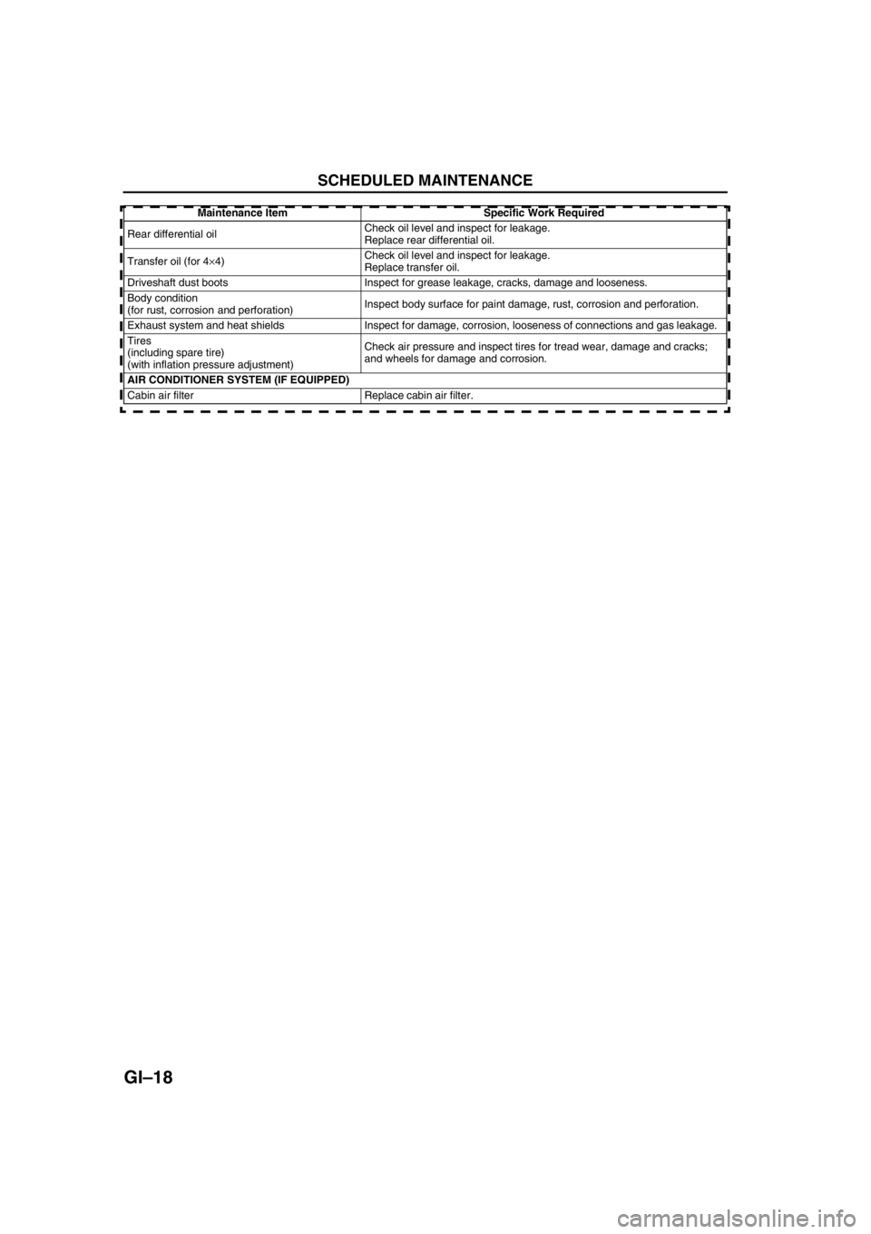
Rear differential oilCheck oil level and inspect for leakage.
Replace rear differential oil.
Transfer oil (for 4×4)Check oil level and inspect for leakage.
Replace transfer oil.
Driveshaft dust boots Inspect for grease leakage, cracks, damage and looseness.
Body condition
(for rust, corrosion and perforation)Inspect body surface for paint damage, rust, corrosion and perforation.
Exhaust system and heat shields Inspect for damage, corrosion, looseness of connections and gas leakage.
Tires
(including spare tire)
(with inflation pressure adjustment)Check air pressure and inspect tires for tread wear, damage and cracks;
and wheels for damage and corrosion.
AIR CONDITIONER SYSTEM (IF EQUIPPED)
Cabin air filter Replace cabin air filter.Maintenance Item Specific Work Required
Page 66 of 909

D–2
OUTLINE
OUTLINE OF CONSTRUCTIONA6E330202000201•The construction and the operation of the oil cooler and the oil filter for the new Mazda6 (GG, GY) MZR-CD (RF
Turbo) engine model is the same as the current Mazda MPV (LW) MZR-CD (RF Turbo) engine model. (See
Mazda MPV Workshop Manual Supplement 1737-1*-02D.)
•The construction and the operation of the lubrication system except for the oil cooler and oil filter for the new
Mazda6 (GG, GY) MZR-CD (RF Turbo) engine model is the same as the current Mazda 626, 626 Station
Wagon (GF, GW) RF Turbo engine model. (European specs.) (See Mazda 626, 626 Station Wagon RF Turbo
Workshop Manual Supplement 1614-10-98D.)
•The construction and the operation of the lubrication system for the new Mazda6 (GG, GY) L8, LF, and L3
engine models is the same as the current Mazda6 (GG) engine model L8, LF, and L3 engine models. (See
Mazda6 Training Manual 3359-1*-02C, Mazda6 Workshop Manual 1730-1*-02C.)
End Of Sie
SPECIFICATIONSA6E330202000202Gasoline engine
* : Always verify the oil level with the dipsticks since the engine oil capacity differs according to dipstick
specifications. (See Mazda6 Workshop Manual 1730-1*-02C Section D.)
Recommended Engine Oil (Gasoline Engine)
•The maintenance intervals on the scheduled maintenance table (See GI–8 SCHEDULED MAINTENANCE
TABLE) can only be supported with the use of following oils.
OUTLINE
ItemSpecification
New
Mazda6
(GG, GY)Current
Mazda6
(GG)New
Mazda6
(GG, GY)Current
Mazda6
(GG)New
Mazda6
(GG, GY)Current
Mazda6
(GG)
L8 LF L3*
Lubrication system Force-fed type
Oil coolerWater-cooled
Oil pressure
(approximate quantity)
[oil temperature: 100°C
{212°F}](kPa {kgf/cm
2, psi})
min [rpm]234—521
{2.39—5.31, 33.9—75.5}
[3,000]395—649
{4.03—6.61,
57.3—94.1}
[3,000]
Oil pumpType Trochoid gear type
Relief pressure
(approximate
quantity) (kPa {kgf/cm
2,
psi})500—600
{5.09—6.11, 72.6—87.0}
Oil filterType Full-flow, Paper element
Bypass pressure
(approximate
quantity)(kPa kgf/cm
2, psi})80—120
{0.9—1.2, 12.8—17.0}
Oil capacity
(approximate
quantity)Total
(dry engine)(L {US qt, lmp qt}) 4.6 {4.8, 4.0} Dipstick A: 4.2 {4.4, 3.7}
Dipstick B: 5.1 {5.4, 4.5}
Oil replacement (L {US qt, lmp qt}) 3.9 {4.0, 3.4} Dipstick A: 3.1 {3.3, 2.7}
Dipstick B: 4.0 {4.2, 3.5}
Oil and oil filter
replacement(L {US qt, lmp qt}) 4.3 {4.5, 3.8} Dipstick A: 3.5 {3.7, 3.1}
Dipstick B: 4.4 {4.6, 3.9}
ItemSpecification
New Mazda6
(GG, GY), Current Mazda6
(GG)New Mazda6
(GG, GY), Current Mazda6
(GG)
L8, LF, L3
Engine oil GradeAPI SL
ACEA A3
Viscosity (SAE) 5W-30, 10W-40 5W-20
RemarksMazda genuine Dexelia oil e.g. —
Page 67 of 909

OUTLINE
D–3
D
Diesel engine
Bold frames: New specifications
Recommended Engine Oil (Diesel Engine)
•The maintenance intervals on the scheduled maintenance table (See GI–8 SCHEDULED MAINTENANCE
TABLE) can only be supported with the use of following oils.
Bold frames: New specifications
End Of Sie
ItemSpecification
New Mazda6
(GG, GY)Current
Mazda 626, 626
Station Wagon
(GF, GW)Current
Mazda MPV
(LW)
MZR-CD (RF Turbo) RF TurboMZR-CD (RF
Turbo)
Lubrication system Force-fed type—
Oil cooler Water-cooled—
Oil pressure
(approximate quantity)
[oil temperature: 100°C {212°F}](kPa {kgf/cm
2, psi})
min [rpm]147 {1.5, 21} [1,000],
343 {3.5, 50} [3,000]—
Oil pumpType Trochoid gear type—Trochoid gear type
Relief pressure
(approximate
quantity)(kPa {kgf/cm
2, psi})
[rpm]580—700
{5.9—7.1,
84.1—101.5}
[3,000]—580—700
{5.9—7.1,
84.1—101.5}
[3,000]
Oil filterTypeFull-flow,
Paper element—Full-flow,
Paper element
Bypass pressure
(approximate
quantity)(kPa kgf/cm
2, psi})78—118
{0.8—1.2,
11.3—17.1} —78—118
{0.8—1.2,
11.3—17.1}
Oil capacity
(approximate
quantity)Total
(dry engine)(L {US qt, lmp qt}) 5.5 {5.8, 4.8} 5.4 {5.7, 4.8} —
Oil replacement (L {US qt, lmp qt}) 4.8 {5.1, 4.2} 4.5 {4.8, 4.0}—
Oil and oil filter
replacement(L {US qt, lmp qt}) 5.0 {5.3 ,4.4} 4.7 {5.0, 4.1} —
ItemSpecification
New Mazda6
(GG, GY)Current
Mazda 626, 626
Station Wagon
(GF, GW)
MZR-CD (RF Turbo) RF Turbo
Engine oil GradeAPI CF CD, CE, CF-4 CD
ACEA B1 or B3 B3 B3 or B4—
Viscosity (SAE) 5W-30 10W-40 5W-30, 10W-30 5W-30, 10W-30
RemarksMazda genuine
Dexelia oil e.g.——
Page 72 of 909
D–8
ENGINE OIL
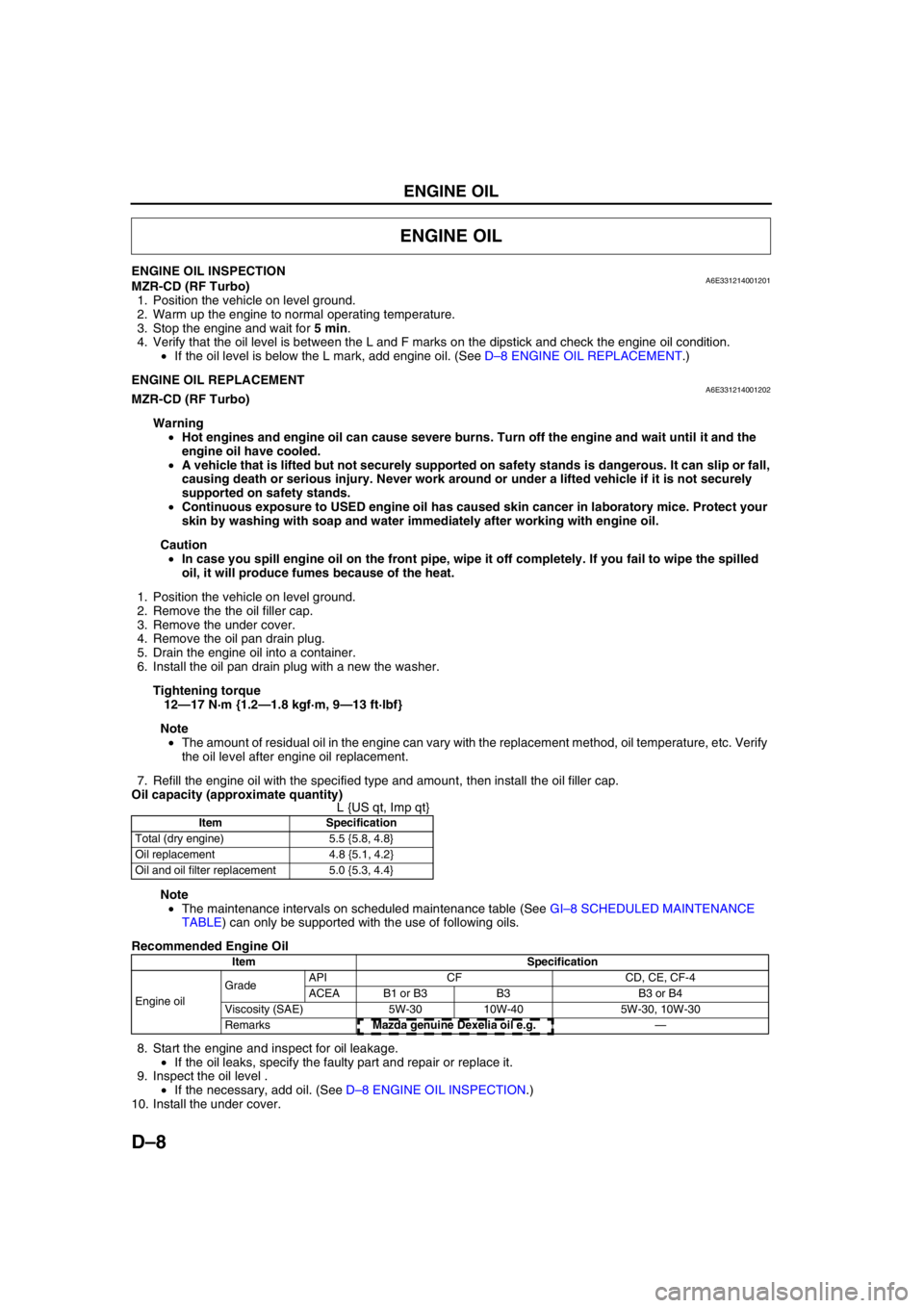
ENGINE OIL INSPECTIONA6E331214001201MZR-CD (RF Turbo)
1. Position the vehicle on level ground.
2. Warm up the engine to normal operating temperature.
3. Stop the engine and wait for 5 min.
4. Verify that the oil level is between the L and F marks on the dipstick and check the engine oil condition.
•If the oil level is below the L mark, add engine oil. (See D–8 ENGINE OIL REPLACEMENT.)
End Of SieENGINE OIL REPLACEMENTA6E331214001202MZR-CD (RF Turbo)
Warning
•Hot engines and engine oil can cause severe burns. Turn off the engine and wait until it and the
engine oil have cooled.
•A vehicle that is lifted but not securely supported on safety stands is dangerous. It can slip or fall,
causing death or serious injury. Never work around or under a lifted vehicle if it is not securely
supported on safety stands.
•Continuous exposure to USED engine oil has caused skin cancer in laboratory mice. Protect your
skin by washing with soap and water immediately after working with engine oil.
Caution
•In case you spill engine oil on the front pipe, wipe it off completely. If you fail to wipe the spilled
oil, it will produce fumes because of the heat.
1. Position the vehicle on level ground.
2. Remove the the oil filler cap.
3. Remove the under cover.
4. Remove the oil pan drain plug.
5. Drain the engine oil into a container.
6. Install the oil pan drain plug with a new the washer.
Tightening torque
12—17 N·m {1.2—1.8 kgf·m, 9—13 ft·lbf}
Note
•The amount of residual oil in the engine can vary with the replacement method, oil temperature, etc. Verify
the oil level after engine oil replacement.
7. Refill the engine oil with the specified type and amount, then install the oil filler cap.
Oil capacity (approximate quantity)
L {US qt, Imp qt}
Note
•The maintenance intervals on scheduled maintenance table (See GI–8 SCHEDULED MAINTENANCE
TABLE) can only be supported with the use of following oils.
Recommended Engine Oil
8. Start the engine and inspect for oil leakage.
•If the oil leaks, specify the faulty part and repair or replace it.
9. Inspect the oil level .
•If the necessary, add oil. (See D–8 ENGINE OIL INSPECTION.)
10. Install the under cover.
End Of Sie
ENGINE OIL
Item Specification
Total (dry engine) 5.5 {5.8, 4.8}
Oil replacement 4.8 {5.1, 4.2}
Oil and oil filter replacement 5.0 {5.3, 4.4}
Item Specification
Engine oil GradeAPI CF CD, CE, CF-4
ACEA B1 or B3 B3 B3 or B4
Viscosity (SAE) 5W-30 10W-40 5W-30, 10W-30
RemarksMazda genuine Dexelia oil e.g. —
Page 187 of 909
ENGINE TUNE-UP, INTAKE-AIR SYSTEM
F2–35
F2
Injection Amount Correction
Note
•Perform this procedure at the recommended interval as described under “Fuel injection system” in
“SCHEDULED MAINTENANCE.”
1. Perform “Engine Tune-up Preparation”. (See F2–34 ENGINE TUNE-UP PREPARATION.)
2. Perform “Injection Amount Correction” using the WDS or equivalent.
MAF Correction
Note
•Perform this procedure after replacing the MAF/IAT sensor or at the recommended interval as described
under “E.G.R. system” in “SCHEDULED MAINTENANCE.”
1. Perform “Engine Tune-up Preparation”. (See F2–34 ENGINE TUNE-UP PREPARATION.)
2. Perform “MAF Correction” using the WDS or equivalent.
End Of Sie
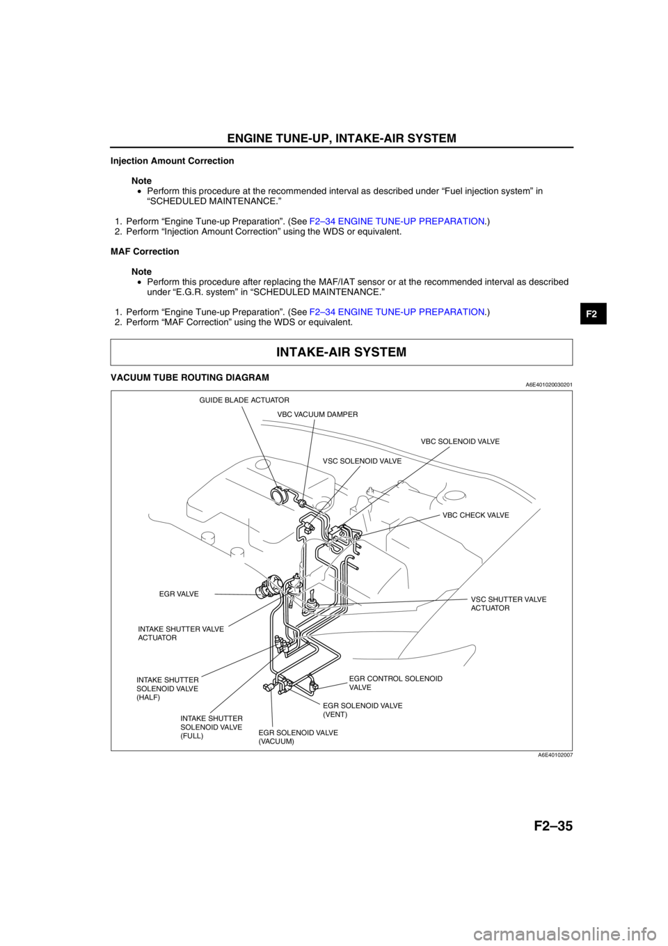
VACUUM TUBE ROUTING DIAGRAMA6E401020030201
End Of Sie
INTAKE-AIR SYSTEM
EGR CONTROL SOLENOID
VA LV E
VBC SOLENOID VALVE
VBC CHECK VALVE
EGR SOLENOID VALVE
(VACUUM)EGR SOLENOID VALVE
(VENT) VSC SOLENOID VALVE
VSC SHUTTER VALVE
ACTUATOR
INTAKE SHUTTER VALVE
ACTUATOREGR VALVE
INTAKE SHUTTER
SOLENOID VALVE
(HALF)
INTAKE SHUTTER
SOLENOID VALVE
(FULL)VBC VACUUM DAMPER GUIDE BLADE ACTUATOR
A6E40102007
Page 646 of 909
M–16
ELECTRONIC 4WD CONTROL SYSTEM
ON-BOARD DIAGNOSTICA6E632227100208Outline
•The on-board diagnostic function allows for detecting malfunctions in the input/output signals when the ignition
key is at the ON position.
•The DLC-2, which combines the failure detection and detection maintenance connectors, has been adopted to
improve serviceability. By connecting a WDS or equivalent to the DLC-2, malfunction diagnosis can be carried
out.
•Using a WDS or equivalent DTCs can be retrieved or erased, depending on the screen display, thus improving
serviceability.
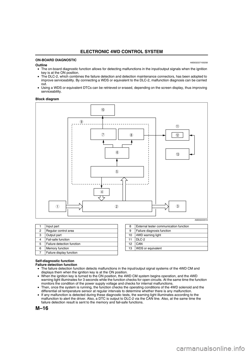
Block diagram
.
Self-diagnostic function
Failure detection function
•The failure detection function detects malfunctions in the input/output signal systems of the 4WD CM and
displays them when the ignition key is at the ON position.
•When the ignition key is turned to the ON position, the 4WD CM system begins operation, and the 4WD
warning light illuminates for 3 seconds while the function checks for open circuits. At the same time the function
monitors the condition of the power supply voltage and checks for internal malfunctions.
•Then, once the system is running, the function checks the operating conditions of the 4WD solenoid and the
differential oil temperature sensor at regular intervals to determine whether there is any malfunction.
•If any malfunction is detected during these diagnostic tests, the warning light illuminates according to the
malfunction to alert the driver. Also, a DTC is output to DLC-2 via the CAN line. Also, at the same time the
failure detection result is sent to the memory and fail-safe functions.
9
87
5
4
3
10
13
11
12
6
12
A6E63222010
1 Input part
2 Regular control area
3 Output part
4 Fail-safe function
5 Failure detection function
6 Memory function
7 Failure display function8 External tester communication function
9 Failure diagnosis function
10 4WD warning light
11 DLC-2
12 CAN
13 WDS or equivalent
Page 647 of 909
ELECTRONIC 4WD CONTROL SYSTEM
M–17
M
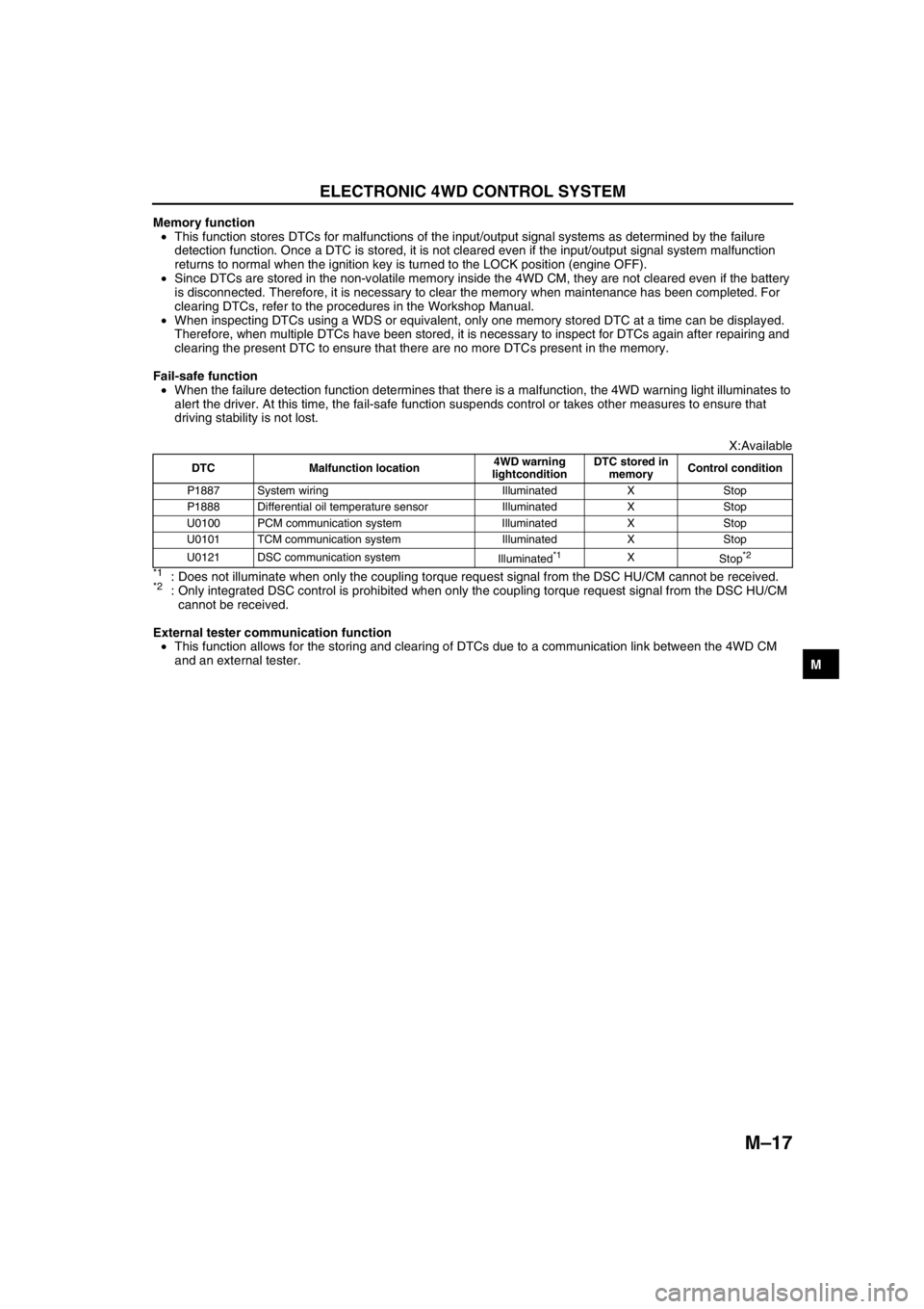
Memory function
•This function stores DTCs for malfunctions of the input/output signal systems as determined by the failure
detection function. Once a DTC is stored, it is not cleared even if the input/output signal system malfunction
returns to normal when the ignition key is turned to the LOCK position (engine OFF).
•Since DTCs are stored in the non-volatile memory inside the 4WD CM, they are not cleared even if the battery
is disconnected. Therefore, it is necessary to clear the memory when maintenance has been completed. For
clearing DTCs, refer to the procedures in the Workshop Manual.
•When inspecting DTCs using a WDS or equivalent, only one memory stored DTC at a time can be displayed.
Therefore, when multiple DTCs have been stored, it is necessary to inspect for DTCs again after repairing and
clearing the present DTC to ensure that there are no more DTCs present in the memory.
Fail-safe function
•When the failure detection function determines that there is a malfunction, the 4WD warning light illuminates to
alert the driver. At this time, the fail-safe function suspends control or takes other measures to ensure that
driving stability is not lost.
X:Available
*1: Does not illuminate when only the coupling torque request signal from the DSC HU/CM cannot be received.*2: Only integrated DSC control is prohibited when only the coupling torque request signal from the DSC HU/CM
cannot be received.
External tester communication function
•This function allows for the storing and clearing of DTCs due to a communication link between the 4WD CM
and an external tester.
End Of Sie
DTC Malfunction location4WD warning
lightconditionDTC stored in
memoryControl condition
P1887 System wiring Illuminated X Stop
P1888 Differential oil temperature sensor Illuminated X Stop
U0100 PCM communication system Illuminated X Stop
U0101 TCM communication system Illuminated X Stop
U0121 DSC communication system
Illuminated
*1X
Stop*2
Page 695 of 909
ELECTRONIC 4WD CONTROL SYSTEM
M–65
M
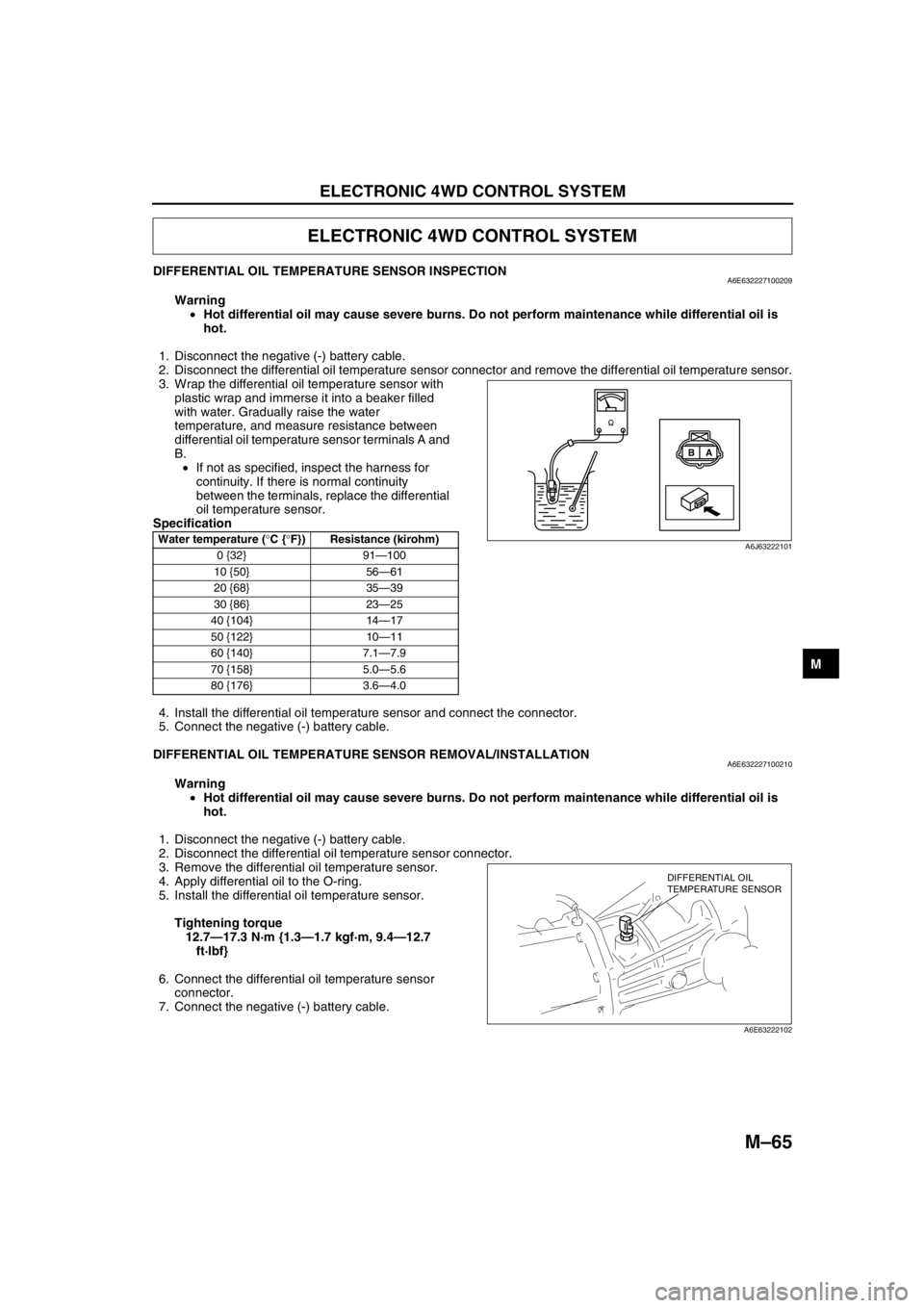
DIFFERENTIAL OIL TEMPERATURE SENSOR INSPECTIONA6E632227100209
Warning
•Hot differential oil may cause severe burns. Do not perform maintenance while differential oil is
hot.
1. Disconnect the negative (-) battery cable.
2. Disconnect the differential oil temperature sensor connector and remove the differential oil temperature sensor.
3. Wrap the differential oil temperature sensor with
plastic wrap and immerse it into a beaker filled
with water. Gradually raise the water
temperature, and measure resistance between
differential oil temperature sensor terminals A and
B.
•If not as specified, inspect the harness for
continuity. If there is normal continuity
between the terminals, replace the differential
oil temperature sensor.
Specification
4. Install the differential oil temperature sensor and connect the connector.
5. Connect the negative (-) battery cable.
End Of Sie
DIFFERENTIAL OIL TEMPERATURE SENSOR REMOVAL/INSTALLATIONA6E632227100210
Warning
•Hot differential oil may cause severe burns. Do not perform maintenance while differential oil is
hot.
1. Disconnect the negative (-) battery cable.
2. Disconnect the differential oil temperature sensor connector.
3. Remove the differential oil temperature sensor.
4. Apply differential oil to the O-ring.
5. Install the differential oil temperature sensor.
Tightening torque
12.7—17.3 N·m {1.3—1.7 kgf·m, 9.4—12.7
ft·lbf}
6. Connect the differential oil temperature sensor
connector.
7. Connect the negative (-) battery cable.
End Of Sie
ELECTRONIC 4WD CONTROL SYSTEM
Water temperature (°C {°F}) Resistance (kirohm)
0 {32} 91—100
10 {50} 56—61
20 {68} 35—39
30 {86} 23—25
40 {104} 14—17
50 {122} 10—11
60 {140} 7.1—7.9
70 {158} 5.0—5.6
80 {176} 3.6—4.0
A B
A6J63222101
DIFFERENTIAL OIL
TEMPERATURE SENSOR
A6E63222102