oil level MAZDA 6 2002 Suplement Owner's Manual
[x] Cancel search | Manufacturer: MAZDA, Model Year: 2002, Model line: 6, Model: MAZDA 6 2002Pages: 909, PDF Size: 17.16 MB
Page 319 of 909

TROUBLESHOOTING
F2–167
F2
SYMPTOM QUICK DIAGNOSIS CHARTA6E408018881202
×: Applicable
Troubleshooting item
1 Melting of main or other fuses
2 MIL illuminates
3 Will not crank×× ×× × ×
4 Hard start/long crank/erratic start/erratic crank×× ×
5 Engine stalls After start/at idle××
6 Cranks normally but will not start××
7 Slow return to idle
8 Engine runs rough/rolling idle××
9 Fast idle/runs on
10 Low idle/stalls during deceleration××
11Engine stalls/quits Acceleration/cruise××
Engine runs rough Acceleration/cruise××
Misses Acceleration/cruise××
Buck/jerk Acceleration/cruise/ deceleration××
Hesitation/stumble Acceleration××
Surges Acceleration/cruise××
12 Lack/loss of power Acceleration/cruise××
13 Knocking/pinging××
14 Poor fuel economy××
15 Emissions compliance×× ×
16 High oil consumption/leakage××××
17 Cooling system concerns Overheating××
18 Cooling system concerns Runs cold
19 Excessive black smoke×
20 Fuel odor (in engine compartment)
21 Engine noise×× × ×
22 Vibration concerns (engine)×
23 A/C does not work sufficiently
24 A/C always on or A/C compressor runs continuously
25 A/C does not cut off under wide open throttle conditions
26 Constant voltage
Starter motor malfunction (Mechanical or electrical)Starter circuit including engine switch is openImproper engine oil levelLow or dead bateryCharging system malfunctionLow engine compressionImproper valve timingHydrolocked egineImproper engine oil viscosityImproper dipstickBase engine malfunctionSeized flywheelImproper tension or damaged drivebelts
Page 320 of 909

F2–168
TROUBLESHOOTING
×: Applicable
Troubleshooting item
1 Melting of main or other fuses
2 MIL illuminates
3 Will not crank
4 Hard start/long crank/erratic start/erratic crank×××
5 Engine stalls After start/at idle×××
6 Cranks normally but will not start××
7 Slow return to idle×
8 Engine runs rough/rolling idle××××
9 Fast idle/runs on×
10 Low idle/stalls during deceleration××
11Engine stalls/quits Acceleration/cruise××××
Engine runs rough Acceleration/cruise×××× ×
Misses Acceleration/cruise××××××
Buck/jerk Acceleration/cruise/ deceleration××××××
Hesitation/stumble Acceleration××××××
Surges Acceleration/cruise××××××
12 Lack/loss of power Acceleration/cruise×××××××
13 Knocking/pinging×××××
14 Poor fuel economy××××
15 Emissions compliance× ××××××
16 High oil consumption/leakage
17 Cooling system concerns Overheating×× × ×
18 Cooling system concerns Runs cold××
19 Excessive black smoke××××
20 Fuel odor (in engine compartment)
21 Engine noise××
22 Vibration concerns (engine)×× ×
23 A/C does not work sufficiently
24 A/C always on or A/C compressor runs continuously
25 A/C does not cut off under wide open throttle conditions
26 Constant voltage
Improper engine coolant levelWater and anti-freeze mixture is improperCooling system malfunction (Radiator, hose,
over-flow system, thermostat, etc.)Cooling fan system malfunctionEngine or transaxle mounts are improperly installedCooling fan No.1 or No.2 seat are improperFuel qualityEngine overheatingIntake-air system clogging or restrictionAir leakage from intake-air systemVSC system malfunctionVacuum leakage
Page 361 of 909

TROUBLESHOOTING
F2–209
F2
NO.16 HIGH OIL CONSUMPTION/LEAKAGEA6E408018881218
Diagnostic Procedure
16 HIGH OIL CONSUMPTION/LEAKAGE
DESCRIPTION•Oil consumption is excessive.
POSSIBLE
CAUSE•Improper engine oil level
•Improper dipstick
•Improper engine oil viscosity
•Engine internal parts malfunction
•Oil leakage
•Turbocharger malfunction
STEP INSPECTION RESULTS ACTION
1 Verify following:
•Proper dipstick
•Proper engine viscosity
•Engine oil level
Are all items okay?Yes Go to next step.
No Service as necessary.
Repeat Step 1.
2 Remove to necessary to inspect turbocharger.
Note
•Do not remove turbocharger.
Inspect if turbocharger compressor wheel is
bent, damaged, or interfering with housing on
vehicle.
Is there any problem?Yes Replace turbocharger.
No Go to next step.
3 Inspect if turbocharger compressor wheel
locknut is loose or has fallen down inside
turbocharger.
Is there any problem?Yes Replace turbocharger.
No Go to next step.
4 Turn turbocharger compressor wheel by hand.
Does wheel turn easily and smoothly?Yes Go to next step.
No Replace turbocharger.
5 Inspect if turbocharger turbine wheel is
damaged, cracked or interfering with housing on
vehicle.
Note
•Inspect all fins on each turbine wheel.
Is there any problem?Yes Replace turbocharger.
No Go to next step.
6 Is any engine oil found inside turbocharger
turbine housing?YesExcessive amount of oil is found:
Replace turbocharger.
Small amount of oil is found:
Wipe oil off of vehicle, then go to next step.
No Go to next step.
7 Is any engine oil found inside turbocharger
compressor housing?Yes Wipe oil off of vehicle, then go to next step.
No Go to next step.
8 Is any engine oil found around oil pipes attached
on turbocharger center housing?Yes If oil leaks from damaged pipe, replace oil pipe.
Then, go to next step.
No Go to next step.
9 Is any engine oil found inside air intake pipes or
hoses?Yes Wipe engine oil off.
No Turbocharger is okay.
Install all parts removed in Step 2.
Then go to next step.
10 Is engine compression correct?
(See B2–8 COMPRESSION INSPECTION)Yes Inspect oil leakage from outside of engine.
No Inspect for following:
•Damaged valve seat
•Worn valve stem and valve guide
•Worn or stuck piston ring
•Worn piston, piston ring or cylinder
Service as necessary.
11 Verify test results.
•If okay, return to diagnostic index to service any additional symptoms.
•If malfunction remains, replace PCM. (See F2–64 PCM REMOVAL/INSTALLATION)
Page 369 of 909

TROUBLESHOOTING
F2–217
F2
NO.21 ENGINE NOISEA6E408018881223
Diagnostic Procedure
21 ENGINE NOISE
DESCRIPTION•Engine noise under hood.
POSSIBLE
CAUSE•Engine internal damage
•Timing belt displacement
•Fuel injector malfunction
•Loose attaching bolts or worn parts
•Improper drive belt tension
•Air leakage from intake-air system
•Incorrect injection timing
•Erratic signal from CKP sensor
•Erratic signal from CMP sensor
•Fuel pressure sensor or related circuit malfunction
•Boost sensor or related circuit malfunction
•Accelerator position sensor or related circuit malfunction
•MAF/IAT sensor or related circuit malfunction
•ECT sensor or related circuit malfunction
•EGR system or malfunction
•IAT sensor No.2 or related circuit malfunction
•Vacuum leakage
•Suction control valve malfunction (built-in supply pump)
•Air leakage from intake-air system
•Air in power steering fluid line
•Turbocharger operating noise
•Solenoid valve operating noise
Warning
The following troubleshooting flow chart contains the fuel system diagnosis and repair
procedures. Read the following warnings before performing the fuel system services:
•Fuel vapor is hazardous. It can easily ignite, causing serious injury and damage. Always keep
sparks and flames away from fuel.
•Fuel line spills and leakage are dangerous. Fuel can ignite and cause serious injury or death
and damage. Fuel can also irritate skin and eyes. To prevent this, always complete “BEFORE
REPAIR PROCEDURE” and “AFTER REPAIR PROCEDURE” described in this manual.
Note
•PCM checks fuel injection amount during a set interval while idling, and automatically corrects it to
maintain engine efficiency. It is normal that engine noise and vibration might be a little louder during
this process.
STEP INSPECTION RESULTS ACTION
1 Is squeal, click or chirp sound present? Yes Inspect engine oil level, solenoid valves installation or
drive belt.
No Go to next step.
2 Is rumble or grind sound present? Yes Inspect drive belt tension or power steering system
fluid level.
If okay, perform power steering fluid line air bleed.
No Go to next step.
3 Is rattle sound present? Yes Inspect location of rattle for loose parts.
No Go to next step.
4 Is hiss sound present? Yes Inspect for vacuum leakage and intake-air system
leakage.
No Go to next step.
5 Is rap or roar sound present? Yes Inspect exhaust system or loose parts.
No Go to next step.
Page 406 of 909

J2–4
MANUAL TRANSAXLE
TRANSAXLE OIL INSPECTIONA6E5212270012011. Park the vehicle on level ground.
2. Remove the filler plug and gasket.
3. Verify that the oil is near the brim of the plug port.
•If the oil level is low, add the specified amount
and type of oil through the filler plug hole.
Specified oil grade
API Service GL-4 or GL-5
Specified oil viscosity
SAE 75W-90
4. Install a new gasket and the filler plug.
Tightening torque
30.0—39.0 N·m
{3.06—3.98 kgf·m, 22.1—28.8 in·lbf}
End Of Sie
TRANSAXLE OIL REPLACEMENTA6E5212270012021. Remove the drain plug with the gasket.
2. Drain the oil into a suitable container.
3. Install a new gasket and the drain plug.
Tightening torque
30.0—39.0 N·m
{3.06—3.98 kgf·m, 22.1—28.8 in·lbf}
4. Remove the filler plug with gasket and add the
specified amount and type of oil through the filler
plug hole until the level reaches the bottom of the
filler plug hole.
Specified oil grade
API Service GL-4 or GL-5
Specified oil viscosity
SAE 75W-90
Capacity (approximate quantity)
2.30 L {2.40 US qt, 2.00 lmp qt}
5. Install a new gasket and the filler plug.
Tightening torque
30.0—39.0 N·m
{3.06—3.98 kgf·m, 22.1—28.8 in·lbf}
End Of Sie
MANUAL TRANSAXLE
DRAIN PLUG FILLER PLUG
A6E5212W010
DRAIN PLUG FILLER PLUG
A6E5212W010
Page 407 of 909

MANUAL TRANSAXLE
J2–5
J2
OIL SEAL (DIFFERENTIAL) REPLACEMENTA6E5212192402011. On level ground, jack up the vehicle and support it evenly on safety stands.
2. Drain the oil from the transaxle.
3. Remove the front wheels and splash shields.
4. Separate the drive shaft and joint shaft from the transaxle. (See Section M.)
5. Remove the oil seals using a screwdriver.
6. Using the SSTs and a hammer, tap each new oil
seal in evenly until the SSTs contact the transaxle
case.
7. Coat the lip of each oil seal with transaxle oil.
8. Insert the drive shaft and joint shaft into the
transaxle. (See Section M.)
9. Install the wheels and splash shields.
10. Add the specified amount and type of oil. (See
J2–4 TRANSAXLE OIL REPLACEMENT.)
End Of SieREVERSE SWITCH INSPECTIONA6E5212190102011. Disconnect the reverse switch connector.
2. Shift the shift lever to each position, and inspect
for continuity between terminals A and B.
•If not as specified, replace the reverse switch.
(See J2–6 REVERSE SWITCH REMOVAL/
INSTALLATION.)
3. Connect the reverse switch connector.
End Of Sie
AME5212W005
49 G030 797
49 U027 003
A6E5212W011
REVERSE SWITCH
A6E5212W012
BA REVERSE SWITCH
PART SIDE CONNENTOR
A6E5212W013
Shift positionConnector terminal
AB:
Continuity
Reverse
Others
A6E5212W014
Page 409 of 909

MANUAL TRANSAXLE
J2–7
J2
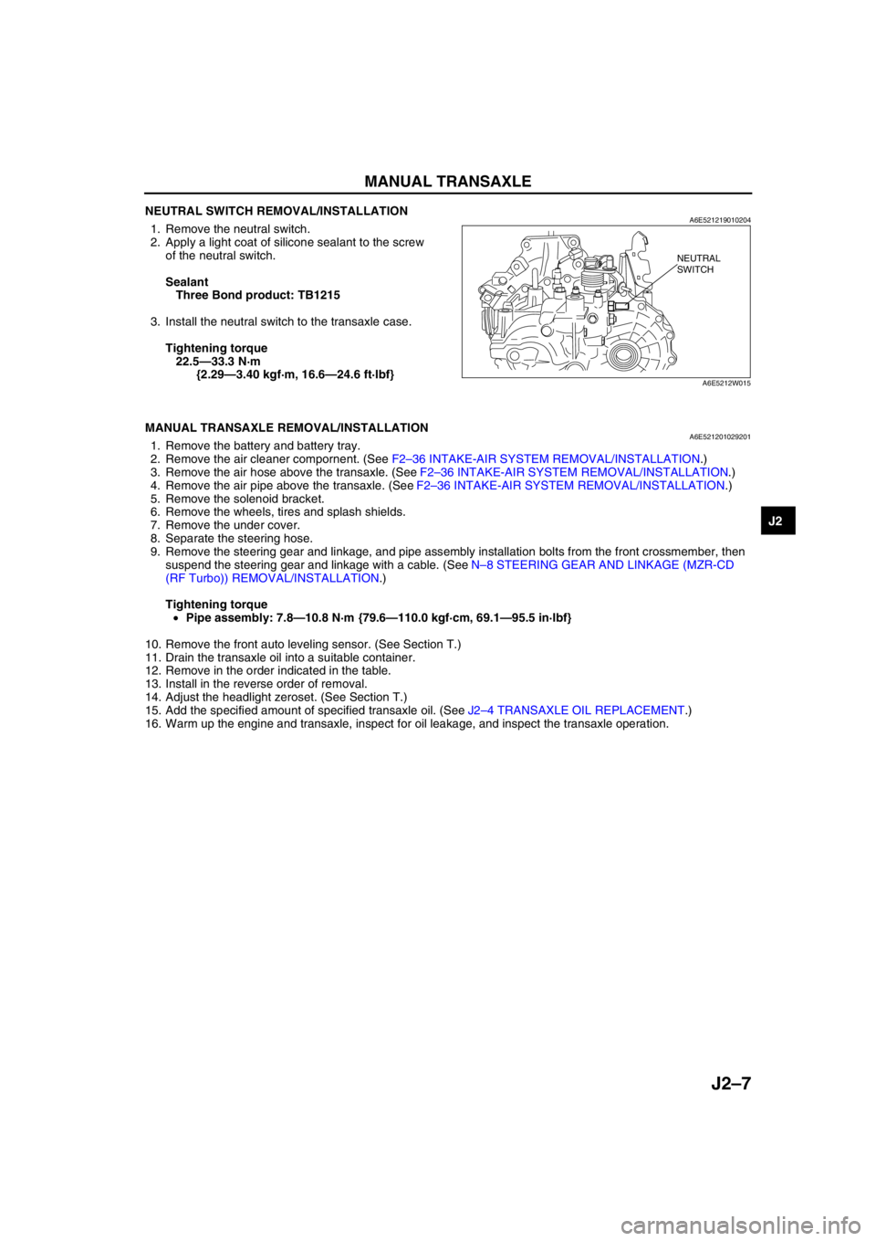
NEUTRAL SWITCH REMOVAL/INSTALLATIONA6E5212190102041. Remove the neutral switch.
2. Apply a light coat of silicone sealant to the screw
of the neutral switch.
Sealant
Three Bond product: TB1215
3. Install the neutral switch to the transaxle case.
Tightening torque
22.5—33.3 N·m
{2.29—3.40 kgf·m, 16.6—24.6 ft·lbf}
End Of Sie
MANUAL TRANSAXLE REMOVAL/INSTALLATIONA6E5212010292011. Remove the battery and battery tray.
2. Remove the air cleaner compornent. (See F2–36 INTAKE-AIR SYSTEM REMOVAL/INSTALLATION.)
3. Remove the air hose above the transaxle. (See F2–36 INTAKE-AIR SYSTEM REMOVAL/INSTALLATION.)
4. Remove the air pipe above the transaxle. (See F2–36 INTAKE-AIR SYSTEM REMOVAL/INSTALLATION.)
5. Remove the solenoid bracket.
6. Remove the wheels, tires and splash shields.
7. Remove the under cover.
8. Separate the steering hose.
9. Remove the steering gear and linkage, and pipe assembly installation bolts from the front crossmember, then
suspend the steering gear and linkage with a cable. (See N–8 STEERING GEAR AND LINKAGE (MZR-CD
(RF Turbo)) REMOVAL/INSTALLATION.)
Tightening torque
•Pipe assembly: 7.8—10.8 N·m {79.6—110.0 kgf·cm, 69.1—95.5 in·lbf}
10. Remove the front auto leveling sensor. (See Section T.)
11. Drain the transaxle oil into a suitable container.
12. Remove in the order indicated in the table.
13. Install in the reverse order of removal.
14. Adjust the headlight zeroset. (See Section T.)
15. Add the specified amount of specified transaxle oil. (See J2–4 TRANSAXLE OIL REPLACEMENT.)
16. Warm up the engine and transaxle, inspect for oil leakage, and inspect the transaxle operation.
NEUTRAL
SWITCH
A6E5212W015
Page 487 of 909

K2–72
AUTOMATIC TRANSAXLE
MECHANICAL SYSTEM TESTA6E571401030209Mechanical System Test Preparation
1. Apply the parking brake and use wheel chocks at the front and rear of the wheels.
2. Inspect the engine coolant. (See Section E.)
3. Inspect the engine oil. (See D–8 ENGINE OIL INSPECTION.)
4. Inspect the ATF levels. (See K2–79 Automatic Transaxle Fluid (ATF) Level Inspection.)
5. Inspect the idle speed and ignition timing in P position. (See F1–22 IDLE SPEED INSPECTION (4WD).)
Line Pressure Test
Note
•Line pressure cannot be measured on the JA5AX-EL automatic transaxle. Measure the low clutch
pressure in place of D and M range line pressures. Measure the reverse clutch pressure in place of R
position line pressure.
1. Engine idling.
(1) Perform mechanical system test preparation. (See K2–72 Mechanical System Test Preparation.)
Warning
•Removing the plug when the ATF is hot can be dangerous. Hot ATF can come out of the opening
and badly burn you. Before removing the square-head plug, allow the ATF to cool.
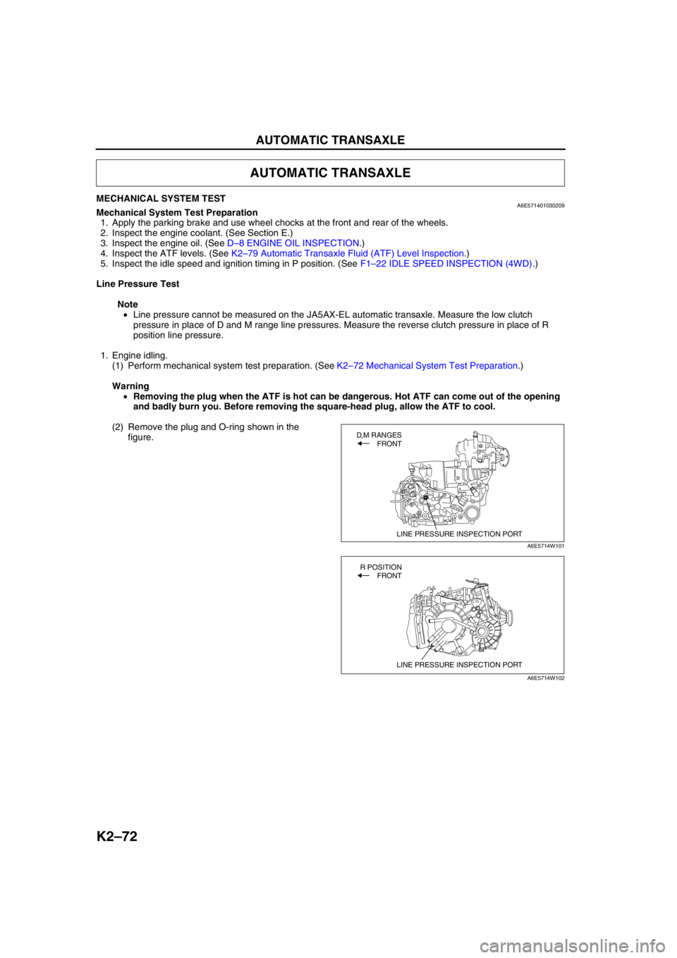
(2) Remove the plug and O-ring shown in the
figure.
AUTOMATIC TRANSAXLE
LINE PRESSURE INSPECTION PORT
D,M RANGES
FRONT
A6E5714W101
LINE PRESSURE INSPECTION PORT
R POSITION
FRONT
A6E5714W102
Page 490 of 909

AUTOMATIC TRANSAXLE
K2–75
K2
Time Lag Test
1. Perform mechanical system test preparation. (See K2–72 Mechanical System Test Preparation.)
2. Start the engine.
3. Warm up the engine until the ATF temperature reaches 60—70°C {140—158°F}. Shift the selector lever from N
position to D range.
4. Use a stopwatch to measure the time it takes from shifting until engagement is felt. Take three measurements
for each test and average the results using the following formula.
Formula
Average time lag = (Time 1 + Time 2 + Time 3) / 3
5. Perform the test for the following shifts in the same manner.
•N position → P position
Time lag
N → D range ... approx. 0.5—1.0 second
N → R position ... approx. 0.6— 1.0 second
Evaluation of time lag test
End Of SieROAD TESTA6E571401030210Road Test Preparation
1. Inspect the engine coolant. (See Section E.)
2. Inspect the engine oil. (See D–8 ENGINE OIL INSPECTION.)
3. Inspect the ATF levels. (See K2–78 AUTOMATIC TRANSAXLE FLUID (ATF) INSPECTION.)
4. Inspect the idle speed and ignition timing in P position. (See F1–22 IDLE SPEED INSPECTION (4WD).)
5. Bring up the engine and transaxle to normal operating temperature.
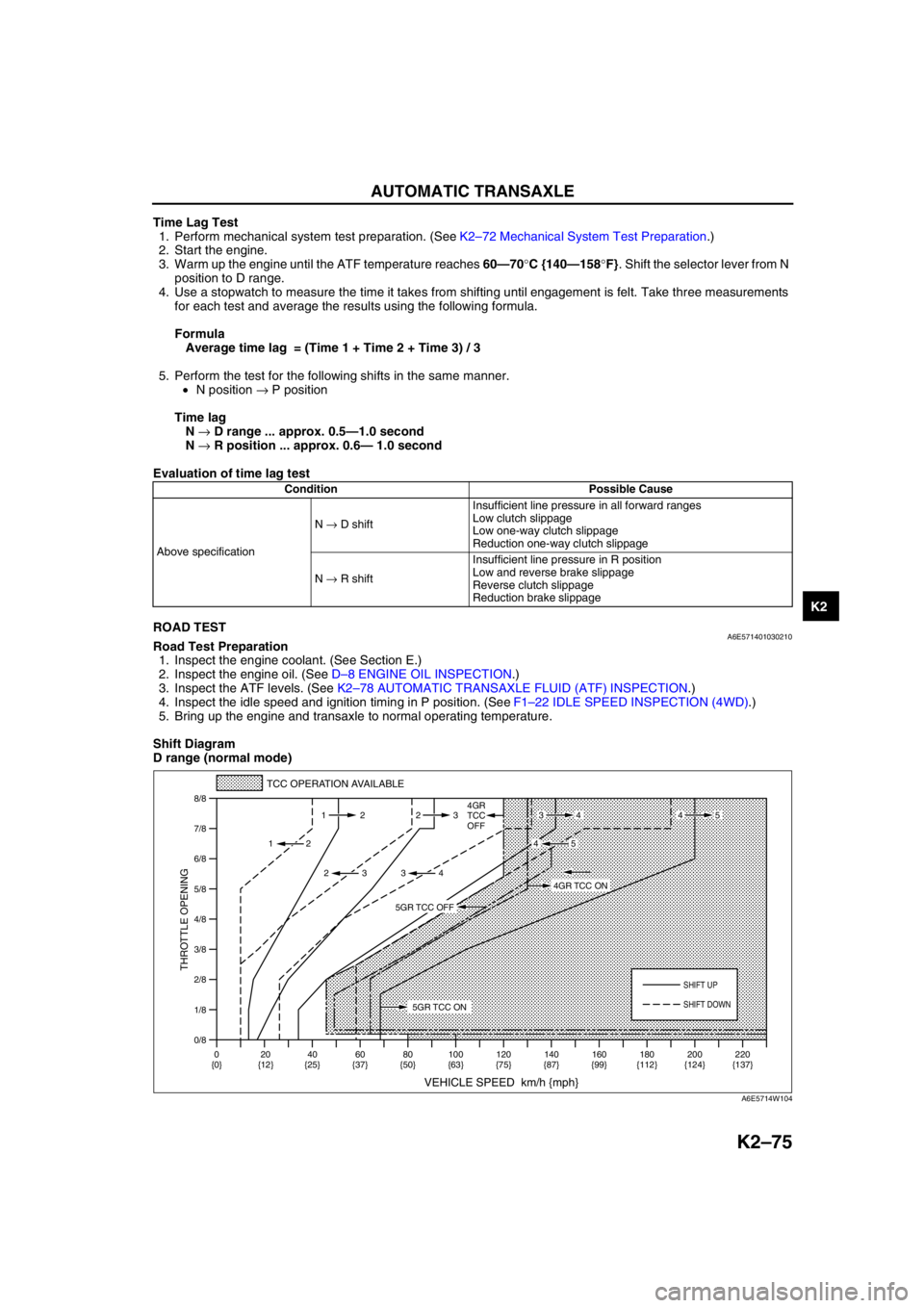
Shift Diagram
D range (normal mode)
Condition Possible Cause
Above specificationN → D shiftInsufficient line pressure in all forward ranges
Low clutch slippage
Low one-way clutch slippage
Reduction one-way clutch slippage
N → R shiftInsufficient line pressure in R position
Low and reverse brake slippage
Reverse clutch slippage
Reduction brake slippage
0/8 1/8
2/8
3/8
4/8
5/8
6/8
7/8
8/8
TCC OPERATION AVAILABLE
VEHICLE SPEED km/h {mph}
THROTTLE OPENING
SHIFT UP
4GR
TCC
OFF
SHIFT DOWN
0
{0}20
{12}40
{25}60
{37}80
{50}100
{63}120
{75}140
{87}160
{99}180
{112}220
{137} 200
{124} 112 23
2
2 232
34
4534
45
5GR TCC ON
4GR TCC ON
5GR TCC OFF
A6E5714W104
Page 494 of 909

AUTOMATIC TRANSAXLE
K2–79
K2
Automatic Transaxle Fluid (ATF) Level Inspection
Caution
•The ATF amount varies according to ATF's temperature. Therefore, when checking the ATF level or
replacing the ATF, use a thermometer to measure the temperature then adjust the ATF amount to
the specified level according to the specified temperature.
1. Park the vehicle on level ground.
2. Apply the parking brake and position wheel chocks securely to prevent the vehicle from rolling.
3. Adjust the length of the thermistor probe measure to the measure same as the dipstick and hold the probe with
a paper holder.
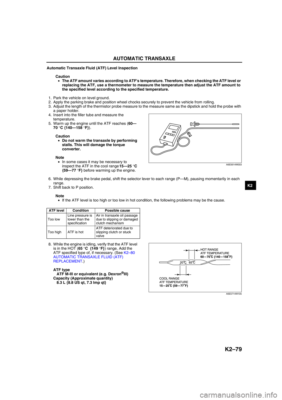
4. Insert into the filler tube and measure the
temperature.
5. Warm up the engine until the ATF reaches (60—
70 °C {140—158 °F}).
Caution
•Do not warm the transaxle by performing
stalls. This will damage the torque
converter.
Note
•In some cases it may be necessary to
inspect the ATF in the cool range 15—25 °C
{59—77 °F} before warming up the engine.
6. While depressing the brake pedal, shift the selector lever to each range (P—M), pausing momentarily in each
range.
7. Shift back to P position.
Note
•If the ATF level is too high or too low in hot condition, the following problems may be the cause.
8. While the engine is idling, verify that the ATF level
is in the HOT (65 °C {149 °F}) range. Add the
ATF specified type of, if necessary. (See K2–80
AUTOMATIC TRANSAXLE FLUID (ATF)
REPLACEMENT.)
ATF type
ATF M-III or equivalent (e.g. Dexron
®III)
Capacity (Approximate quantity)
8.3 L {8.8 US qt, 7.3 Imp qt}
End Of Sie
ATF level Condition Possible cause
Too lowLine pressure is
lower than the
specificationAir in transaxle oil passage
due to slipping or damaged
clutch mechanism
Too high ATF is hotATF deteriorated due to
slipping clutch or stuck
valve
A6E5614W003
A6E5714W105