steering MAZDA 6 2002 Suplement Owner's Manual
[x] Cancel search | Manufacturer: MAZDA, Model Year: 2002, Model line: 6, Model: MAZDA 6 2002Pages: 909, PDF Size: 17.16 MB
Page 409 of 909
MANUAL TRANSAXLE
J2–7
J2
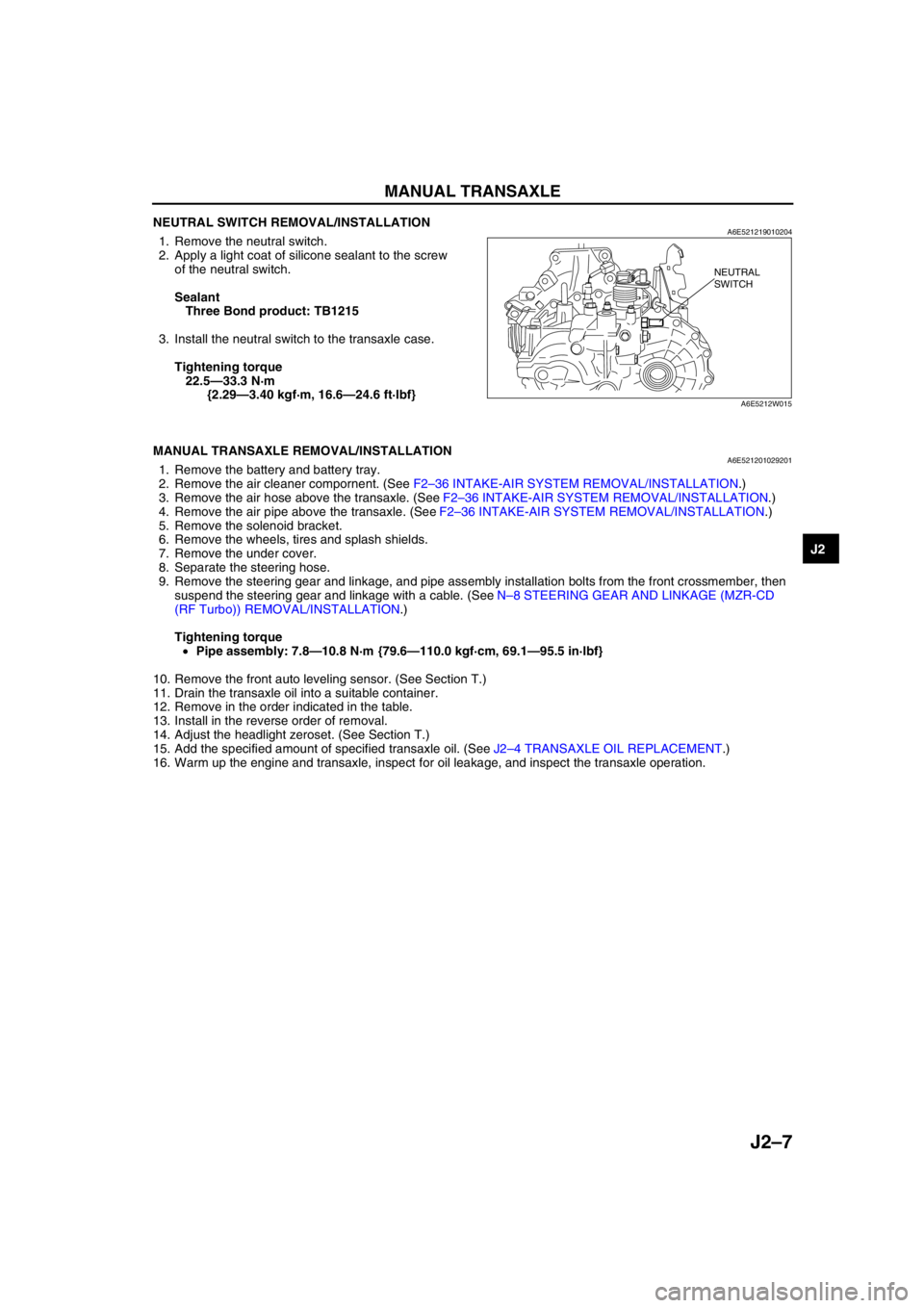
NEUTRAL SWITCH REMOVAL/INSTALLATIONA6E5212190102041. Remove the neutral switch.
2. Apply a light coat of silicone sealant to the screw
of the neutral switch.
Sealant
Three Bond product: TB1215
3. Install the neutral switch to the transaxle case.
Tightening torque
22.5—33.3 N·m
{2.29—3.40 kgf·m, 16.6—24.6 ft·lbf}
End Of Sie
MANUAL TRANSAXLE REMOVAL/INSTALLATIONA6E5212010292011. Remove the battery and battery tray.
2. Remove the air cleaner compornent. (See F2–36 INTAKE-AIR SYSTEM REMOVAL/INSTALLATION.)
3. Remove the air hose above the transaxle. (See F2–36 INTAKE-AIR SYSTEM REMOVAL/INSTALLATION.)
4. Remove the air pipe above the transaxle. (See F2–36 INTAKE-AIR SYSTEM REMOVAL/INSTALLATION.)
5. Remove the solenoid bracket.
6. Remove the wheels, tires and splash shields.
7. Remove the under cover.
8. Separate the steering hose.
9. Remove the steering gear and linkage, and pipe assembly installation bolts from the front crossmember, then
suspend the steering gear and linkage with a cable. (See N–8 STEERING GEAR AND LINKAGE (MZR-CD
(RF Turbo)) REMOVAL/INSTALLATION.)
Tightening torque
•Pipe assembly: 7.8—10.8 N·m {79.6—110.0 kgf·cm, 69.1—95.5 in·lbf}
10. Remove the front auto leveling sensor. (See Section T.)
11. Drain the transaxle oil into a suitable container.
12. Remove in the order indicated in the table.
13. Install in the reverse order of removal.
14. Adjust the headlight zeroset. (See Section T.)
15. Add the specified amount of specified transaxle oil. (See J2–4 TRANSAXLE OIL REPLACEMENT.)
16. Warm up the engine and transaxle, inspect for oil leakage, and inspect the transaxle operation.
NEUTRAL
SWITCH
A6E5212W015
Page 411 of 909

MANUAL TRANSAXLE
J2–9
J2
No.1 Engine Mount Bracket Removal Note
1. Separate the fuel pipe nearby engine hanger.
2. Support the engine using the SST before
removing the No.1 engine mount.
3. Remove the No.1 engine mount.
Manual Transaxle Removal Note
1. Remove the stud of the No.4 engine mount.
2. Loosen the SST (49 E017 5A0)and lean the
engine toward the transaxle.
3. Support the transaxle on a jack.
4. Remove the transaxle mounting bolts.
5. Remove the transaxle.
9 Lower arm (front, rear) ball joint
(See Section R)
10 Damper fork
11 Tie-rod end ball joint
(See N–8 STEERING GEAR AND LINKAGE
(MZR-CD (RF Turbo)) REMOVAL/INSTALLATION)
12 Stabilizer control link
13 Drive shaft (left side)
(SeeSection M)
14 Drive shaft (right side)
(SeeSection M)
15 Joint shaft
(SeeSection M)
16 Flexible pipe
(See F2–57 EXHAUST SYSTEM REMOVAL/
INSTALLATION)17 No.1 engine mount
(See J2–9 No.1 Engine Mount Bracket Removal
Note)
(See J2–11 No.1 Engine Mount Installation Note)
18 Crossmember bracket
19 Crossmember, steering pipe
(See Section R)
20 No.4 engine mount bracket
(See J2–10 No.4 Engine Mount Installation Note)
21 No.4 engine mount rubber
(See J2–10 No.4 Engine Mount Installation Note)
22 Transaxle mounting bolt (lower side)
23 Manual transaxle
(See J2–9 Manual Transaxle Removal Note)
(See J2–10 Manual Transaxle Installation Note)
49 E017 5A0
A6E5212W019
STUD
A6E5212W020
A6E5212W021
Page 514 of 909
AUTOMATIC TRANSAXLE
K2–99
K2
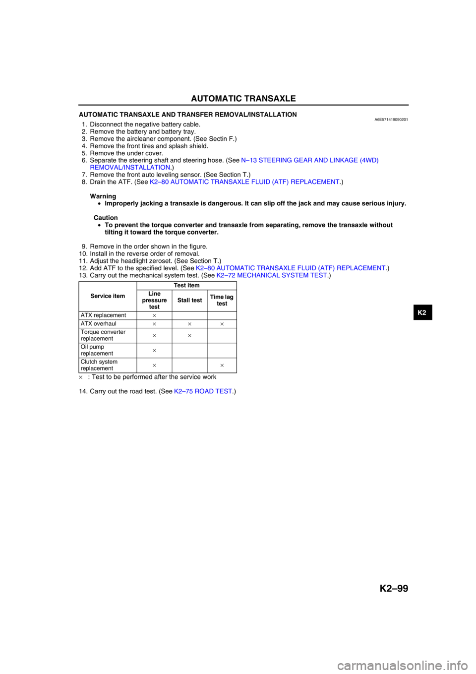
AUTOMATIC TRANSAXLE AND TRANSFER REMOVAL/INSTALLATIONA6E5714190902011. Disconnect the negative battery cable.
2. Remove the battery and battery tray.
3. Remove the aircleaner component. (See Sectin F.)
4. Remove the front tires and splash shield.
5. Remove the under cover.
6. Separate the steering shaft and steering hose. (See N–13 STEERING GEAR AND LINKAGE (4WD)
REMOVAL/INSTALLATION.)
7. Remove the front auto leveling sensor. (See Section T.)
8. Drain the ATF. (See K2–80 AUTOMATIC TRANSAXLE FLUID (ATF) REPLACEMENT.)
Warning
•Improperly jacking a transaxle is dangerous. It can slip off the jack and may cause serious injury.
Caution
•To prevent the torque converter and transaxle from separating, remove the transaxle without
tilting it toward the torque converter.
9. Remove in the order shown in the figure.
10. Install in the reverse order of removal.
11. Adjust the headlight zeroset. (See Section T.)
12. Add ATF to the specified level. (See K2–80 AUTOMATIC TRANSAXLE FLUID (ATF) REPLACEMENT.)
13. Carry out the mechanical system test. (See K2–72 MECHANICAL SYSTEM TEST.)
×: Test to be performed after the service work
14. Carry out the road test. (See K2–75 ROAD TEST.)
Service itemTest item
Line
pressure
testStall testTime lag
test
ATX replacement×
ATX overhaul×××
Torque converter
replacement××
Oil pump
replacement×
Clutch system
replacement××
Page 516 of 909
AUTOMATIC TRANSAXLE
K2–101
K2
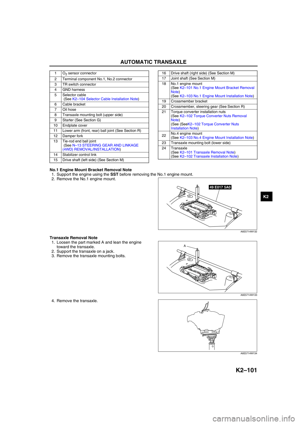
No.1 Engine Mount Bracket Removal Note
1. Support the engine using the SST before removing the No.1 engine mount.
2. Remove the No.1 engine mount.
Transaxle Removal Note
1. Loosen the part marked A and lean the engine
toward the transaxle.
2. Support the transaxle on a jack.
3. Remove the transaxle mounting bolts.
4. Remove the transaxle.
1O2 sensor connector
2 Terminal component No.1, No.2 connector
3 TR switch connector
4 GND harness
5 Selector cable
(See K2–104 Selector Cable Installation Note)
6 Cable bracket
7 Oil hose
8 Transaxle mounting bolt (upper side)
9 Starter (See Section G)
10 Endplate cover
11 Lower arm (front, rear) ball joint (See Section R)
12 Damper fork
13 Tie-rod end ball joint
(See N–13 STEERING GEAR AND LINKAGE
(4WD) REMOVAL/INSTALLATION)
14 Stabilizer control link
15 Drive shaft (left side) (See Section M)16 Drive shaft (right side) (See Section M)
17 Joint shaft (See Section M)
18 No.1 engine mount
(See K2–101 No.1 Engine Mount Bracket Removal
Note)
(See K2–103 No.1 Engine Mount Installation Note)
19 Crossmember bracket
20 Crossmember, steering gear (See Section R)
21 Torque converter installation nuts
(See K2–102 Torque Converter Nuts Removal
Note)
(See (SeeK2–102 Torque Converter Nuts
Installation Note)
22No.4 engine mount
(See K2–103 No.4 Engine Mount Installation Note)
23 Transaxle mounting bolt (lower side)
24 Transaxle
(See K2–101 Transaxle Removal Note)
(See K2–102 Transaxle Installation Note)
49 E017 5A0
A6E5714W132
A
A6E5714W133
A6E5714W134
Page 715 of 909
N–1
N
NSTEERING SYSTEM
OUTLINE................................................................ N-2
OUTLINE OF CONSTRUCTION.......................... N-2
FEATURES .......................................................... N-2
SPECIFICATIONS ............................................... N-2
STRUCTURAL VIEW ...........................................N-3
OUTLINE................................................................ N-5
SUPPLEMENTAL SERVICE
INFORMATION .................................................N-5
ENGINE SPEED SENSING POWER
STEERING........................................................... N-6
POWER STEERING FLUID INSPECTION ..........N-6
STEERING GEAR AND LINKAGE
(MZR-CD (RF TURBO))
REMOVAL/INSTALLATION ..............................N-8
STEERING GEAR AND LINKAGE (4WD)
REMOVAL/INSTALLATION ............................N-13
POWER STEERING OIL PUMP
(MZR-CD (RF TURBO))
REMOVAL/INSTALLATION ............................N-16
POWER STEERING OIL PUMP
(MZR-CD (RF TURBO))
DISASSEMBLY/ASSEMBLY .......................... N-17 FEATURES
SERVICE
Page 716 of 909
N–2
OUTLINE
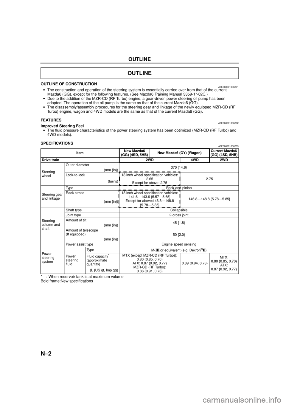
OUTLINE OF CONSTRUCTIONA6E660201036201•The construction and operation of the steering system is essentially carried over from that of the current
Mazda6 (GG), except for the following features. (See Mazda6 Training Manual 3359-1*-02C.)
• Due to the addition of the MZR-CD (RF Turbo) engine, a gear-driven power steering oil pump has been
adopted. The operation of the oil pump is the same as that of the current Mazda6 (GG).
• The disassembly/assembly procedures for the steering gear and linkage of the newly equipped MZR-CD (RF
Turbo) engine, wagon and 4WD models are the same as that of the current Mazda6 (GG).
End Of Sie
FEATURESA6E660201036202Improved Steering Feel
• The fluid pressure characteristics of the power steering system has been optimized (MZR-CD (RF Turbo) and
4WD models).
End Of Sie
SPECIFICATIONSA6E660201036203
* : When reservoir tank is at maximum volume
Bold frame:New specifications
End Of Sie
OUTLINE
Item New Mazda6
(GG) (4SD, 5HB) New Mazda6 (GY) (Wagon) Current Mazda6
(GG) (4SD, 5HB)
Drive train 2WD 4WD 2WD
Steering
wheel Outer diameter
370 {14.6}
(mm {in})
Lock-to-lock 18 inch wheel specification vehicles: 2.65
Except for above: 2.75 2.75
(turns)
Steering gear
and linkage Type Rack-and-pinion
Rack stroke 18 inch wheel specification vehicles:
141.6—143.6 {5.57—5.65}
Except for above:146.8—148.8
{5.78—5.85} 146.8—148.8 {5.78—5.85}
(mm {in})
Steering
column and
shaft Shaft type Collapsible
Joint type 2-cross joint
Amount of tilt
45 {1.8}
(mm {in})
Amount of telescope
(If equipped) 50 {2.0}
(mm {in})
Powe r
steering
system Power assist type Engine speed sensing
Pow er
steering
fluid
Ty p e
M-
III or equivalent (e.g. Dexron®II)
Fluid capacity
*
(approximate
quantity) MTX (except MZR-CD (RF Turbo)):
0.80 {0.85, 0.70}
ATX: 0.87 {0.92, 0.77} MZR-CD (RF Turbo):
0.86 {0.91, 0.76} 0.89 {0.94, 0.78}
MTX:
0.80 {0.85, 0.70}
AT X :
0.87 {0.92, 0.77}
(L {US qt, Imp qt})
Page 717 of 909

OUTLINE
N–3
N
STRUCTURAL VIEWA6E660201036204MZR-CD (RF Turbo)
.
7
6
7
6
5
5
3
1
2
4
A6E63162001
1L.H.D.
2 R.H.D.
3 Steering wheel
4 Steering column and shaft5 Steering gear
6 Power steering oil pump
7 Fluid reservoir
Page 718 of 909

N–4
OUTLINE
4WD
.
End Of Sie
8
7
5
4
3
1
2
6
5
6
8
7
A6E63162002
1 L.H.D.
2 R.H.D.
3 Steering wheel
4 Steering column and shaft5 Steering gear
6 Power steering oil pump
7 Fluid reservoir
8 Cooling pipe
Page 719 of 909

OUTLINE
N–5
N
SUPPLEMENTAL SERVICE INFORMATIONA6E660201034201•The following changes have been made since publication of the Mazda6 Workshop Manual (1730-1*-02C).
Power steering fluid
•Inspection procedure has been modified.
Steering gear and linkage (MZR-CD (RF Turbo))
•Removal/installation procedure has been added.
Steering gear and linkage (4WD)
•Removal/installation procedure has been added.
Power steering oil pump (MZR-CD (RF Turbo))
•Removal/installation procedure has been added.
•Disassembly/assembly procedure has been added.
End Of Sie
OUTLINE
Page 720 of 909

N–6
ENGINE SPEED SENSING POWER STEERING
POWER STEERING FLUID INSPECTIONA6E661432040201Fluid Level Inspection
1. Inspect the power steering fluid level.
•Add fluid to the specified level as necessary.
Fluid specification
ATF M-III or equivalent (e.g. Dexron
®II)
Fluid Leakage Inspection
Caution
•If the steering wheel is kept in the fully turned position for more than 5 seconds, the fluid
temperature will rise excessively and adversely affect the oil pump.
1. Start the engine and let it idle.
2. Turn the steering wheel fully to the left and right to apply fluid pressure.
Note
•The points where fluid leakage may occur are indicated in the figure.
3. Inspect for fluid leakage.
•If fluid leakage is found, replace the related pipe or hose.
ENGINE SPEED SENSING POWER STEERING
L.H.D.
ATX
MTX
R.H.D.
ATX
MTX MZR-CD (RF Turbo)
EXCEPT MZR-CD (RF Turbo)L.H.D
R.H.D
A6E66142001