center console MAZDA 6 2002 Workshop Manual Suplement
[x] Cancel search | Manufacturer: MAZDA, Model Year: 2002, Model line: 6, Model: MAZDA 6 2002Pages: 909, PDF Size: 17.16 MB
Page 415 of 909

SHIFT MECHANISM
J2–13
J2
Select Cable Installation Note
1. Remove the center console.
2. Make sure that the shift lever (transaxle side) is in neutral.
3. Unlock the lock pice of the select cable (shift lever
side) in the order shown in the figure.
4. Shift the sift lever to neutral.
5. Lock the lock pice of the selector cable (shift
cable side) in the order shown in the figure.
6. Install the center console.
7. Shift the shift lever from neutral to other position,
and make sure that there are no other
components in that area to interfere with the
lever.
End Of Sie
LOCK PIECE SAFETY
LOCK
1
2
A6E5214W002
LOCK PIECE SAFETY
LOCK
2
1
A6E5214W003
Page 533 of 909

K2–118
AUTOMATIC TRANSAXLE SHIFT MECHANISM
SELECTOR CABLE ADJUSTMENTA6E5716465002011. Remove the center console.
2. Shift the selector lever to P position.
3. Unlock the lock piece of the selector cable
(selector lever side) in the order shown in the
figure.
4. Verify that the manual shaft is in P position.
5. Lock the lock piece of the selector cable (selector
lever side) in the order shown in the figure.
6. Install the center console.
7. Shift the selector lever from P position to M range,
and make sure that there are no other
components in that area to interfere with the lever.
End Of Sie
1
2
SAFETY
LOCK
LOCK PIECE
A6E5716W102
2
1
SAFETY
LOCK
LOCK PIECE
A6E5716W103
Page 538 of 909

ON-BOARD DIAGNOSTIC
K2–123
K2
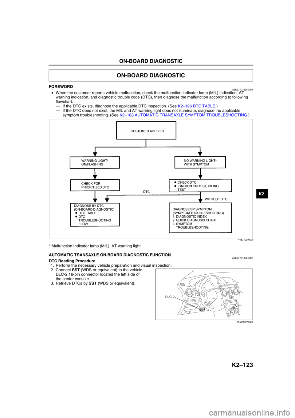
FOREWORDA6E577018901201•When the customer reports vehicle malfunction, check the malfunction indicator lamp (MIL) indication, AT
warning indication, and diagnostic trouble code (DTC), then diagnose the malfunction according to following
flowchart.
—If the DTC exists, diagnose the applicable DTC inspection. (See K2–126 DTC TABLE.)
—If the DTC does not exist, the MIL and AT warning light does not illuminate, diagnose the applicable
symptom troubleshooting. (See K2–183 AUTOMATIC TRANSAXLE SYMPTOM TROUBLESHOOTING.)
*:Malfunction Indicator lamp (MIL), AT warning light
End Of Sie
AUTOMATIC TRANSAXLE ON-BOARD DIAGNOSTIC FUNCTIONA6E577018901202DTC Reading Procedure
1. Perform the necessary vehicle preparation and visual inspection.
2. Connect SST (WDS or equivalent) to the vehicle
DLC-2 16-pin connector located the left side of
the center console.
3. Retrieve DTCs by SST (WDS or equivalent).
End Of Sie
ON-BOARD DIAGNOSTIC
YMU102WBX
DLC-2
A6E3970W002
Page 750 of 909

PARKING BRAKE SYSTEM, DYNAMIC STABILITY CONTROL
P–17
P
PARKING BRAKE (LEVER TYPE) ADJUSTMENTA6E6914440002011. Start the engine and depress the brake pedal several times.
2. Stop the engine.
3. For the 2WD model, remove the rear ashtray case behind the center console
4. For the 4WD model, remove the 4 screws (back side) and pull up the rear of the center console, then remove
the rear ashtray case.
5. Turn the adjusting nut as shown in the figure.
6. After adjustment, inspect the following points:
(1) Turn the ignition switch to ON, pull the parking
brake lever one notch, and verify that the
parking brake warning light illuminates.
(2) Verify that the rear brakes do not drag.
End Of Sie
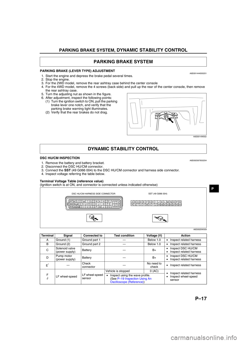
DSC HU/CM INSPECTIONA6E6920676502041. Remove the battery and battery bracket.
2. Disconnect the DSC HU/CM connector.
3. Connect the SST (49 G066 004) to the DSC HU/CM connector and harness side connector.
4. Inspect voltage referring the table below.
Terminal Voltage Table (reference value)
(Ignition switch is at ON, and connector is connected unless indicated otherwise)
PARKING BRAKE SYSTEM
A6E6914W002
DYNAMIC STABILITY CONTROL
Terminal Signal Connected to Test condition Voltage (V) Action
A Ground (1) Ground part 1—Below 1.0•Inspect related harness
B Ground (2) Ground part 2—Below 1.0•Inspect related harness
CSolenoid valve
(power supply)Battery—B+•Inspect DSC HU/CM
•Inspect related harness
DPump motor
(power supply)Battery—B+•Inspect DSC HU/CM
•Inspect related harness
E
*—Check
connector—No need to
check•Inspect related harness
F
JLF wheel-speedLF wheel-speed
sensorVehicle is stopped 0 (AC)
•Inspect related harness
•Inspect wheel-speed
sensor •Inspect using the wave profile.
(See P–19 Inspection Using An
Oscilloscope (Reference))
SST (49 G066 004)
AQ
B
CDE
FG
HI
J DSC HU/CM HARNESS SIDE CONNECTOR
A
C E
H
K N Q
T
W Z AC AF
F I L O R U X
AA AD AG
G
J
M P S
V
Y AB AE AHB
DKN
T
WZ
AC
AFLO
RU
XAA
ADAGMP
SV
YAB
AEAH
A6E6920W009