service interval MAZDA 6 2002 Workshop Manual Suplement
[x] Cancel search | Manufacturer: MAZDA, Model Year: 2002, Model line: 6, Model: MAZDA 6 2002Pages: 909, PDF Size: 17.16 MB
Page 11 of 909

GI–8
SCHEDULED MAINTENANCE
SCHEDULED MAINTENANCE TABLEA6E203400013202For Europe (L.H.D. U.K.)
Chart symbols:
I : Inspect and clean, repair, adjust, or replace if necessary.
R:Replace
C : Clean
Remarks:
SCHEDULED MAINTENANCE
•To ensure efficient operation of the engine and all systems related to emission control, the ignition and fuel systems must
be serviced regularly. It is strongly recommended that all servicing related to these systems be done by an authorized
Mazda Dealer.
•After the described period, continue to follow the described maintenance at the recommended intervals.
•Refer below for a description of items marked* in the maintenance chart.
*1: If the vehicle is operated under any of the following conditions, change the engine oil and oil filter every 10,000 km
(6,250 miles) or shorter.
a. Driving in dusty conditions.
b. Extended periods of idling or low speed operation.
c. Driving for long period in cold temperatures or driving regularly at short distance only.
*2: Also inspect and adjust the power steering and air conditioner drive belts, if installed.
*3: If the brakes are used extensively (for example, continuous hard driving or mountain driving) or if the vehicle is
operated in extremely humid climates, change the brake fluid annually.
*4: If the vehicle is operated in very dusty or sandy areas, clean and if necessary, replace the air cleaner element more
often than the recommended intervals.
*5: Replacement of the timing belt is required at every 100,000 km (62,500 miles).
Failure to replace the timing belt may result in damage to the engine.
*6: Replacement of the timing belt is required at every 120,000 km (75,000 miles).
Failure to replace the timing belt may result in damage to the engine.
*7: If the vehicle is operated under any of the following conditions, change the rear differential oil
every 40,000 km (25,000 miles).
a. Towing a trailer or using a car - top carrier
b. Driving in dusty, sandy or wet condition
c. Extended periods of idling or low speed operation
d. Repeated short trips of less than 16 km (10 miles)
*8: If this component has been submerged in water, the oil should be changed.
Maintenance ItemMaintenance Interval (Number of months or km (miles), whichever comes first)
Months 12 24 36 48 60 72 84 96 108
×1000 km 20 40 60 80 100 120 140 160 180
×1000 miles 12.52537.55062.57587.5100112.5
GASOLINE ENGINE
Spark plugs Replace every 100,000 km (62,500 miles)
Air cleaner element *4 R R R
E.G.R. system I I
DIESEL ENGINE
Engine valve clearance I I
Engine timing beltFinland, Sweden, Norway*5 Replace every 100,000 km (62,500 miles)
Others*6 Replace every 120,000 km (75,000 miles)
Fuel filter R R R
Fuel injection system I I I I
Air cleaner element *4CCRCCRCCR
E.G.R. system I I I
GASOLINE and DIESEL ENGINE
Engine oil *1RRRRRRRRR
Engine oil filter *1RRRRRRRRR
Drive belts *2 I I I
Cooling system (including coolant level adjustment) I I I I
Page 13 of 909

GI–10
SCHEDULED MAINTENANCE
For Israel
Chart symbols:
I : Inspect and clean, repair, adjust, or replace if necessary.
R:Replace
C : Clean
Remarks:
•To ensure efficient operation of the engine and all systems related to emission control, the ignition and fuel systems must
be serviced regularly. It is strongly recommended that all servicing related to these systems be done by an authorized
Mazda Dealer.
•After the described period, continue to follow the described maintenance at the recommended intervals.
•Refer below for a description of items marked* in the maintenance chart.
*1: If the vehicle is operated under any of the following conditions, change the engine oil and oil filter every 10,000 km
(6,000 miles) or shorter.
a. Driving in dusty conditions.
b. Extended periods of idling or low speed operation.
c. Driving for long period in cold temperatures or driving regularly at short distance only.
*2: Also inspect and adjust the power steering and air conditioner drive belts, if installed.
*3: If the brakes are used extensively (for example, continuous hard driving or mountain driving) or if the vehicle is
operated in extremely humid climates, change the brake fluid annually.
*4: If the vehicle is operated in very dusty or sandy areas, clean and if necessary, replace the air cleaner element more
often than the recommended intervals.
*5: This is a full function check of electrical systems such as lights, wiper and washer systems (including wiper blades),
and power windows.
Maintenance ItemMaintenance Interval (Number of months or km (miles), whichever comes first)
Months 12 24 36 48 60 72 84 96 108 120 132 144
×1000 km 15 30 45 60 75 90 105 120 135 150 165 180
×1000 miles 9 18 27 36 45 54 63 72 81 90 99 108
ENGINE
Drive belts *2IIIIIIIIIII I
Engine oil *1RRRRRRRRRRR R
Engine oil filter *1RRRRRRRRRRR R
COOLING SYSTEM
Cooling system
(Including coolant level adjustment)IIIII I
Engine coolantReplace at first 4 years or 90,000 km (54,000 miles);
after that, every 2 years
FUEL SYSTEM
Air cleaner element *4CCCRCCCRCCC R
Fuel filter R R
Fuel lines & hoses IIIII I
IGNITION SYSTEM
Spark plugs Replace every 90,000 km (54,000 miles)
EMISSION CONTROL SYSTEM
Evaporative system I I I
E.G.R. system (if installed) I I I
ELECTRICAL SYSTEM
Battery electrolyte level & specific gravity I I I I I I I I I I I I
All electrical system *5IIIIIIIIIII I
CHASSIS & BODY
Brake & clutch pedals IIIIIIIIIII I
Brake lines, hoses & connections I I I I I I I I I I I I
Brake fluid *3IRIRIRIRIRI R
Parking brake IIIIIIIIIII I
Power brake unit & hoses IIIIIIIIIII I
Disc brakes IIIIIIIIIII I
Power steering fluid, lines, hoses, and
connectionsIIIIIIIIIII I
Page 14 of 909

SCHEDULED MAINTENANCE
GI–11
GI
For GCC
Chart symbols:
I : Inspect and clean, repair, adjust, or replace if necessary.
R : Replace
T:Tighten
C : Clean
Remarks:
End Of Sie
Steering operation & linkages IIIII I
Manual transaxle oil R R
Automatic transaxle fluid level IIIII I
Front & rear suspension & ball joints IIIII
Driveshaft dust boots IIIII
Exhaust system & heat shields IIIII I
Bolts & nuts on seats IIIII I
Body condition (for rust, corrosion & perforation) Inspect annually
Cabin air filter (if installed) R R R R R R R R R R R RMaintenance ItemMaintenance Interval (Number of months or km (miles), whichever comes first)
Months 12 24 36 48 60 72 84 96 108 120 132 144
×1000 km 15 30 45 60 75 90 105 120 135 150 165 180
×1000 miles 9 18 27 36 45 54 63 72 81 90 99 108
•To ensure efficient operation of the engine and all systems related to emission control, the ignition and fuel systems must
be serviced regularly. It is strongly recommended that all servicing related to these systems be done by an authorized
Mazda Dealer.
•After the described period, continue to follow the described maintenance at the recommended intervals.
•Refer below for a description of items marked* in the maintenance chart.
*1: If the vehicle is operated under any of the following conditions, change the engine oil and oil filter more often than
recommended intervals.
a. Driving in dusty conditions.
b. Extended periods of idling or low speed operation.
c. Driving for long period in cold temperatures or driving regularly at short distance only.
*2: Also inspect and adjust the power steering and air conditioner drive belts, if installed.
*3: If the brakes are used extensively (for example, continuous hard driving or mountain driving) or if the vehicle is
operated in extremely humid climates, change the brake fluid annually.
*4: If the vehicle is operated in very dusty or sandy areas, clean and if necessary, replace the air cleaner element more
often than the recommended intervals.
*5: This is a full function check of electrical systems such as lights, wiper and washer systems (including wiper blades),
and power windows.
*6: If the vehicle is operated under any of the following conditions, change the rear differential oil
every 45,000 km (27,000 miles).
a. Towing a trailer or using a car - top carrier
b. Driving in dusty, sandy or wet condition
c. Extended periods of idling or low speed operation
d. Repeated short trips of less than 16 km (10 miles)
*7: If this component has been submerged in water, the oil should be changed.
Maintenance ItemMaintenance Interval (Number of months or km (miles), whichever comes first)
Months 6 121824303642485460667278849096
×1000 km
10 20 30 40 50 60 70 80 90 100 110 120 130 140 150 160
×1000 miles6.25 12.5 18.75 25 31.25 37.5 43.75 50 56.25 62.5 68.75 75 81.25 87.5 93.75 100
ENGINE
Engine valve clearance (leaded fuel) I I I I
Drive belts *2IIIIIIIIIIIIIIII
Engine oil *1RRRRRRRRRRRRRRRR
Engine oil filter *1RRRRRRRRRRRRRRRR
COOLING SYSTEM
Cooling system IIIIIIII
Engine coolant Replace every 2 years
Page 288 of 909

F2–136
ON-BOARD DIAGNOSTIC
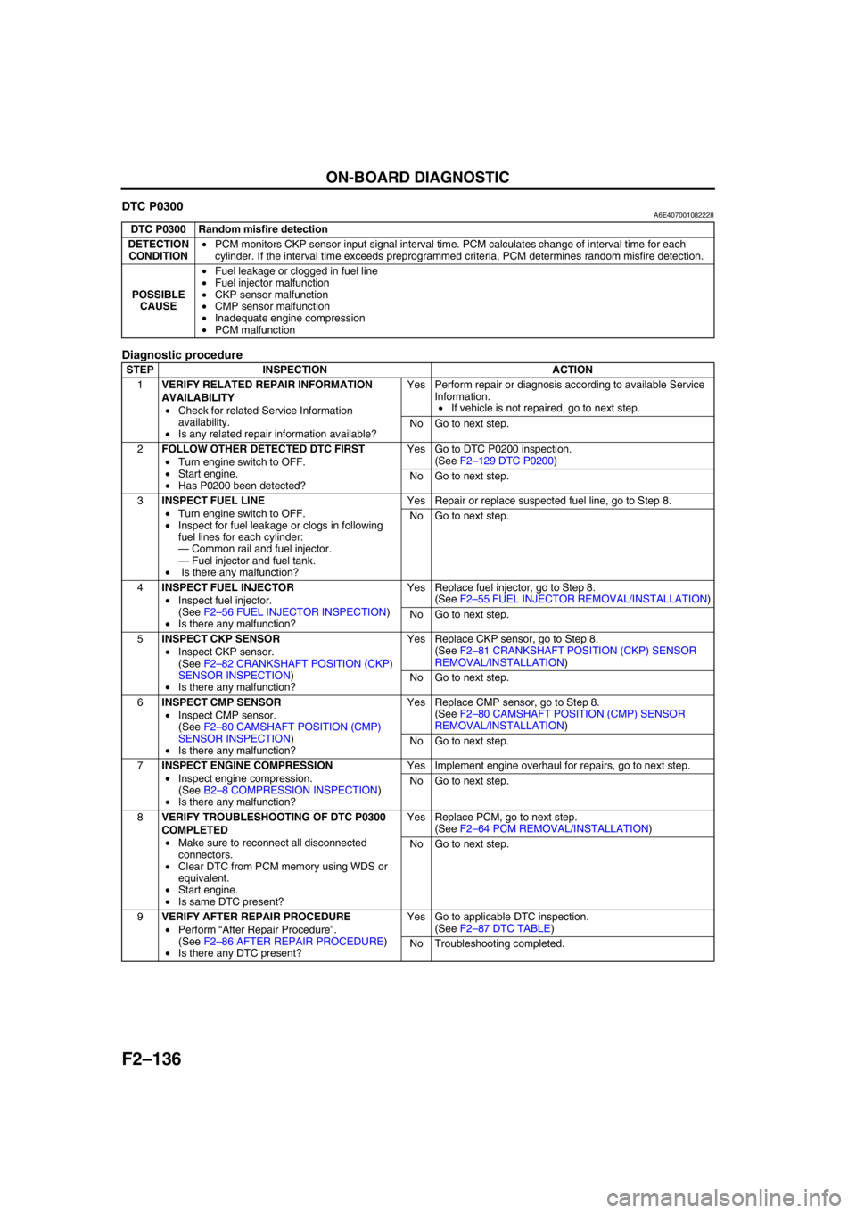
DTC P0300A6E407001082228
Diagnostic procedure
End Of Sie
DTC P0300 Random misfire detection
DETECTION
CONDITION•PCM monitors CKP sensor input signal interval time. PCM calculates change of interval time for each
cylinder. If the interval time exceeds preprogrammed criteria, PCM determines random misfire detection.
POSSIBLE
CAUSE•Fuel leakage or clogged in fuel line
•Fuel injector malfunction
•CKP sensor malfunction
•CMP sensor malfunction
•Inadequate engine compression
•PCM malfunction
STEP INSPECTION ACTION
1VERIFY RELATED REPAIR INFORMATION
AVAILABILITY
•Check for related Service Information
availability.
•Is any related repair information available?Yes Perform repair or diagnosis according to available Service
Information.
•If vehicle is not repaired, go to next step.
No Go to next step.
2FOLLOW OTHER DETECTED DTC FIRST
•Turn engine switch to OFF.
•Start engine.
•Has P0200 been detected?Yes Go to DTC P0200 inspection.
(See F2–129 DTC P0200)
No Go to next step.
3INSPECT FUEL LINE
•Turn engine switch to OFF.
•Inspect for fuel leakage or clogs in following
fuel lines for each cylinder:
—Common rail and fuel injector.
—Fuel injector and fuel tank.
• Is there any malfunction?Yes Repair or replace suspected fuel line, go to Step 8.
No Go to next step.
4INSPECT FUEL INJECTOR
•Inspect fuel injector.
(See F2–56 FUEL INJECTOR INSPECTION)
•Is there any malfunction?Yes Replace fuel injector, go to Step 8.
(See F2–55 FUEL INJECTOR REMOVAL/INSTALLATION)
No Go to next step.
5INSPECT CKP SENSOR
•Inspect CKP sensor.
(See F2–82 CRANKSHAFT POSITION (CKP)
SENSOR INSPECTION)
•Is there any malfunction?Yes Replace CKP sensor, go to Step 8.
(See F2–81 CRANKSHAFT POSITION (CKP) SENSOR
REMOVAL/INSTALLATION)
No Go to next step.
6INSPECT CMP SENSOR
•Inspect CMP sensor.
(See F2–80 CAMSHAFT POSITION (CMP)
SENSOR INSPECTION)
•Is there any malfunction?Yes Replace CMP sensor, go to Step 8.
(See F2–80 CAMSHAFT POSITION (CMP) SENSOR
REMOVAL/INSTALLATION)
No Go to next step.
7INSPECT ENGINE COMPRESSION
•Inspect engine compression.
(See B2–8 COMPRESSION INSPECTION)
•Is there any malfunction?Yes Implement engine overhaul for repairs, go to next step.
No Go to next step.
8VERIFY TROUBLESHOOTING OF DTC P0300
COMPLETED
•Make sure to reconnect all disconnected
connectors.
•Clear DTC from PCM memory using WDS or
equivalent.
•Start engine.
•Is same DTC present?Yes Replace PCM, go to next step.
(See F2–64 PCM REMOVAL/INSTALLATION)
No Go to next step.
9VERIFY AFTER REPAIR PROCEDURE
•Perform “After Repair Procedure”.
(See F2–86 AFTER REPAIR PROCEDURE)
•Is there any DTC present?Yes Go to applicable DTC inspection.
(See F2–87 DTC TABLE)
No Troubleshooting completed.
Page 369 of 909

TROUBLESHOOTING
F2–217
F2
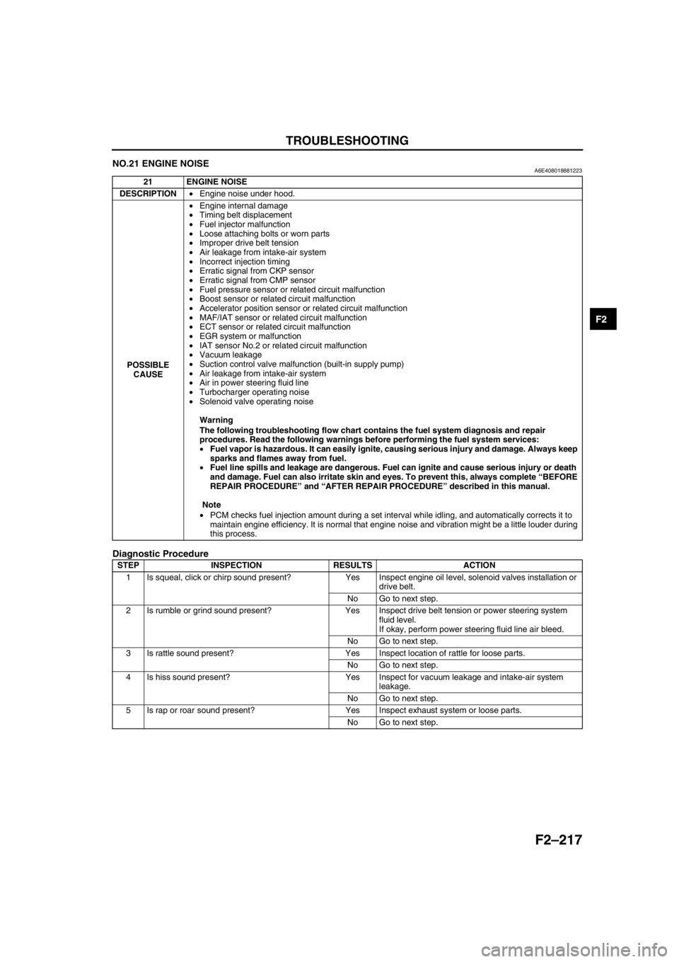
NO.21 ENGINE NOISEA6E408018881223
Diagnostic Procedure
21 ENGINE NOISE
DESCRIPTION•Engine noise under hood.
POSSIBLE
CAUSE•Engine internal damage
•Timing belt displacement
•Fuel injector malfunction
•Loose attaching bolts or worn parts
•Improper drive belt tension
•Air leakage from intake-air system
•Incorrect injection timing
•Erratic signal from CKP sensor
•Erratic signal from CMP sensor
•Fuel pressure sensor or related circuit malfunction
•Boost sensor or related circuit malfunction
•Accelerator position sensor or related circuit malfunction
•MAF/IAT sensor or related circuit malfunction
•ECT sensor or related circuit malfunction
•EGR system or malfunction
•IAT sensor No.2 or related circuit malfunction
•Vacuum leakage
•Suction control valve malfunction (built-in supply pump)
•Air leakage from intake-air system
•Air in power steering fluid line
•Turbocharger operating noise
•Solenoid valve operating noise
Warning
The following troubleshooting flow chart contains the fuel system diagnosis and repair
procedures. Read the following warnings before performing the fuel system services:
•Fuel vapor is hazardous. It can easily ignite, causing serious injury and damage. Always keep
sparks and flames away from fuel.
•Fuel line spills and leakage are dangerous. Fuel can ignite and cause serious injury or death
and damage. Fuel can also irritate skin and eyes. To prevent this, always complete “BEFORE
REPAIR PROCEDURE” and “AFTER REPAIR PROCEDURE” described in this manual.
Note
•PCM checks fuel injection amount during a set interval while idling, and automatically corrects it to
maintain engine efficiency. It is normal that engine noise and vibration might be a little louder during
this process.
STEP INSPECTION RESULTS ACTION
1 Is squeal, click or chirp sound present? Yes Inspect engine oil level, solenoid valves installation or
drive belt.
No Go to next step.
2 Is rumble or grind sound present? Yes Inspect drive belt tension or power steering system
fluid level.
If okay, perform power steering fluid line air bleed.
No Go to next step.
3 Is rattle sound present? Yes Inspect location of rattle for loose parts.
No Go to next step.
4 Is hiss sound present? Yes Inspect for vacuum leakage and intake-air system
leakage.
No Go to next step.
5 Is rap or roar sound present? Yes Inspect exhaust system or loose parts.
No Go to next step.
Page 646 of 909

M–16
ELECTRONIC 4WD CONTROL SYSTEM
ON-BOARD DIAGNOSTICA6E632227100208Outline
•The on-board diagnostic function allows for detecting malfunctions in the input/output signals when the ignition
key is at the ON position.
•The DLC-2, which combines the failure detection and detection maintenance connectors, has been adopted to
improve serviceability. By connecting a WDS or equivalent to the DLC-2, malfunction diagnosis can be carried
out.
•Using a WDS or equivalent DTCs can be retrieved or erased, depending on the screen display, thus improving
serviceability.
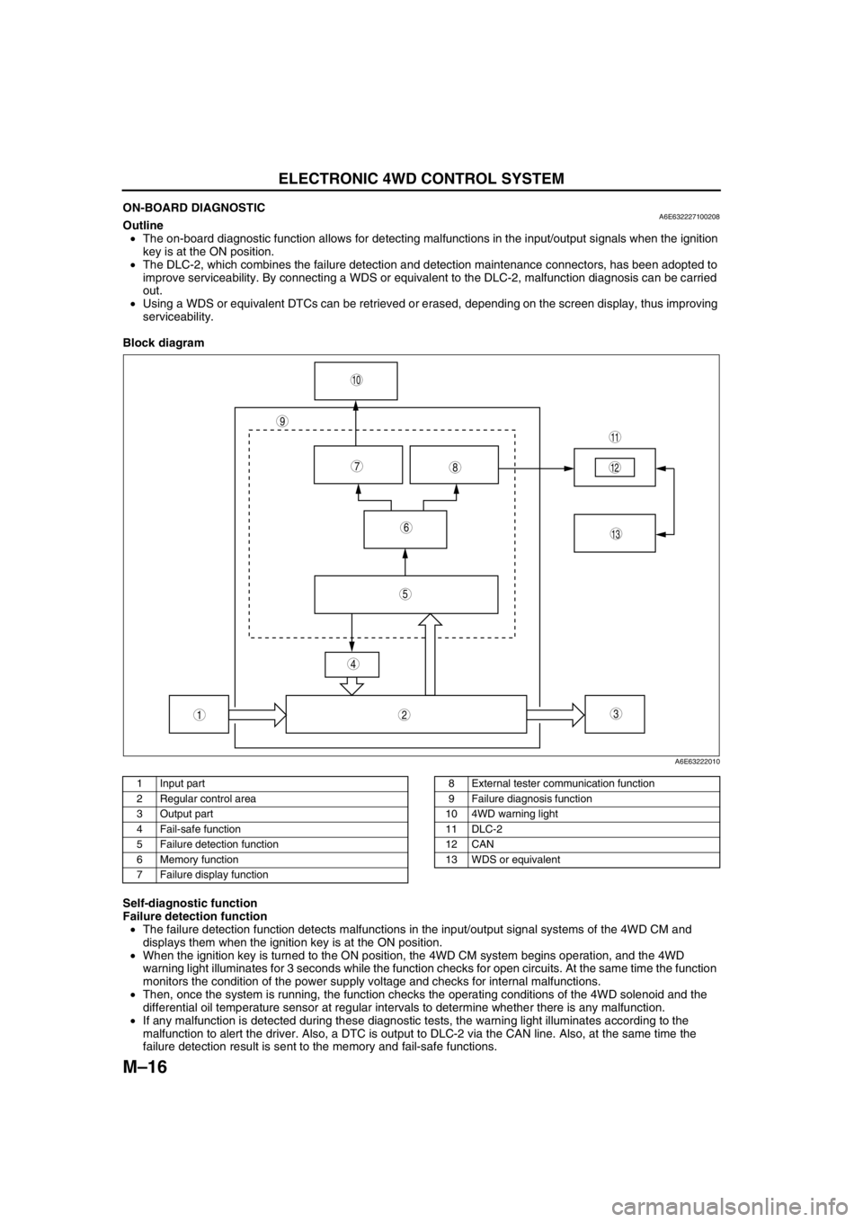
Block diagram
.
Self-diagnostic function
Failure detection function
•The failure detection function detects malfunctions in the input/output signal systems of the 4WD CM and
displays them when the ignition key is at the ON position.
•When the ignition key is turned to the ON position, the 4WD CM system begins operation, and the 4WD
warning light illuminates for 3 seconds while the function checks for open circuits. At the same time the function
monitors the condition of the power supply voltage and checks for internal malfunctions.
•Then, once the system is running, the function checks the operating conditions of the 4WD solenoid and the
differential oil temperature sensor at regular intervals to determine whether there is any malfunction.
•If any malfunction is detected during these diagnostic tests, the warning light illuminates according to the
malfunction to alert the driver. Also, a DTC is output to DLC-2 via the CAN line. Also, at the same time the
failure detection result is sent to the memory and fail-safe functions.
9
87
5
4
3
10
13
11
12
6
12
A6E63222010
1 Input part
2 Regular control area
3 Output part
4 Fail-safe function
5 Failure detection function
6 Memory function
7 Failure display function8 External tester communication function
9 Failure diagnosis function
10 4WD warning light
11 DLC-2
12 CAN
13 WDS or equivalent