timing belt MAZDA 6 2002 Workshop Manual Suplement
[x] Cancel search | Manufacturer: MAZDA, Model Year: 2002, Model line: 6, Model: MAZDA 6 2002Pages: 909, PDF Size: 17.16 MB
Page 11 of 909

GI–8
SCHEDULED MAINTENANCE
SCHEDULED MAINTENANCE TABLEA6E203400013202For Europe (L.H.D. U.K.)
Chart symbols:
I : Inspect and clean, repair, adjust, or replace if necessary.
R:Replace
C : Clean
Remarks:
SCHEDULED MAINTENANCE
•To ensure efficient operation of the engine and all systems related to emission control, the ignition and fuel systems must
be serviced regularly. It is strongly recommended that all servicing related to these systems be done by an authorized
Mazda Dealer.
•After the described period, continue to follow the described maintenance at the recommended intervals.
•Refer below for a description of items marked* in the maintenance chart.
*1: If the vehicle is operated under any of the following conditions, change the engine oil and oil filter every 10,000 km
(6,250 miles) or shorter.
a. Driving in dusty conditions.
b. Extended periods of idling or low speed operation.
c. Driving for long period in cold temperatures or driving regularly at short distance only.
*2: Also inspect and adjust the power steering and air conditioner drive belts, if installed.
*3: If the brakes are used extensively (for example, continuous hard driving or mountain driving) or if the vehicle is
operated in extremely humid climates, change the brake fluid annually.
*4: If the vehicle is operated in very dusty or sandy areas, clean and if necessary, replace the air cleaner element more
often than the recommended intervals.
*5: Replacement of the timing belt is required at every 100,000 km (62,500 miles).
Failure to replace the timing belt may result in damage to the engine.
*6: Replacement of the timing belt is required at every 120,000 km (75,000 miles).
Failure to replace the timing belt may result in damage to the engine.
*7: If the vehicle is operated under any of the following conditions, change the rear differential oil
every 40,000 km (25,000 miles).
a. Towing a trailer or using a car - top carrier
b. Driving in dusty, sandy or wet condition
c. Extended periods of idling or low speed operation
d. Repeated short trips of less than 16 km (10 miles)
*8: If this component has been submerged in water, the oil should be changed.
Maintenance ItemMaintenance Interval (Number of months or km (miles), whichever comes first)
Months 12 24 36 48 60 72 84 96 108
×1000 km 20 40 60 80 100 120 140 160 180
×1000 miles 12.52537.55062.57587.5100112.5
GASOLINE ENGINE
Spark plugs Replace every 100,000 km (62,500 miles)
Air cleaner element *4 R R R
E.G.R. system I I
DIESEL ENGINE
Engine valve clearance I I
Engine timing beltFinland, Sweden, Norway*5 Replace every 100,000 km (62,500 miles)
Others*6 Replace every 120,000 km (75,000 miles)
Fuel filter R R R
Fuel injection system I I I I
Air cleaner element *4CCRCCRCCR
E.G.R. system I I I
GASOLINE and DIESEL ENGINE
Engine oil *1RRRRRRRRR
Engine oil filter *1RRRRRRRRR
Drive belts *2 I I I
Cooling system (including coolant level adjustment) I I I I
Page 16 of 909
GI–12
SCHEDULED MAINTENANCE
GIGENE RAL INFORMATION
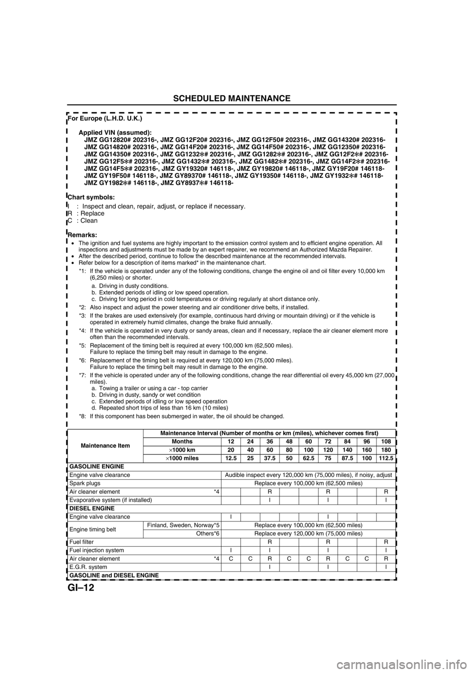
For Europe (L.H.D. U.K.)
Applied VIN (assumed):
JMZ GG12820# 202316-, JMZ GG12F20# 202316-, JMZ GG12F50# 202316-, JMZ GG14320# 202316-
JMZ GG14820# 202316-, JMZ GG14F20# 202316-, JMZ GG14F50# 202316-, JMZ GG12350# 202316-
JMZ GG14350# 202316-, JMZ GG1232✻
✻✻ ✻
# 202316-, JMZ GG1282✻
✻✻ ✻
# 202316-, JMZ GG12F2✻
✻✻ ✻
# 202316-
JMZ GG12F5✻
✻✻ ✻
# 202316-, JMZ GG1432✻
✻✻ ✻
# 202316-, JMZ GG1482✻
✻✻ ✻
# 202316-, JMZ GG14F2✻
✻✻ ✻
# 202316-
JMZ GG14F5✻
✻✻ ✻
# 202316-, JMZ GY19320# 146118-, JMZ GY19820# 146118-, JMZ GY19F20# 146118-
JMZ GY19F50# 146118-, JMZ GY89370# 146118-, JMZ GY19350# 146118-, JMZ GY1932✻
✻✻ ✻
# 146118-
JMZ GY1982✻
✻✻ ✻
# 146118-, JMZ GY8937✻
✻✻ ✻
# 146118-
Chart symbols:
I : Inspect and clean, repair, adjust, or replace if necessary.
R:Replace
C : Clean
Remarks:
S CHEDULED MAINTE NANCE
•The ignition and fuel systems are highly important to the emission control system and to efficient engine operation. All
inspections and adjustments must be made by an expert repairer, we recommend an Authorized Mazda Repairer.
•After the described period, continue to follow the described maintenance at the recommended intervals.
•Refer below for a description of items marked* in the maintenance chart.
*1: If the vehicle is operated under any of the following conditions, change the engine oil and oil filter every 10,000 km
(6,250 miles) or shorter.
a. Driving in dusty conditions.
b. Extended periods of idling or low speed operation.
c. Driving for long period in cold temperatures or driving regularly at short distance only.
*2: Also inspect and adjust the power steering and air conditioner drive belts, if installed.
*3: If the brakes are used extensively (for example, continuous hard driving or mountain driving) or if the vehicle is
operated in extremely humid climates, change the brake fluid annually.
*4: If the vehicle is operated in very dusty or sandy areas, clean and if necessary, replace the air cleaner element more
often than the recommended intervals.
*5: Replacement of the timing belt is required at every 100,000 km (62,500 miles).
Failure to replace the timing belt may result in damage to the engine.
*6: Replacement of the timing belt is required at every 120,000 km (75,000 miles).
Failure to replace the timing belt may result in damage to the engine.
*7: If the vehicle is operated under any of the following conditions, change the rear differential oil every 45,000 km (27,000
miles).
a. Towing a trailer or using a car - top carrier
b. Driving in dusty, sandy or wet condition
c. Extended periods of idling or low speed operation
d. Repeated short trips of less than 16 km (10 miles)
*8: If this component has been submerged in water, the oil should be changed.
Maintenance ItemMaintenance Interval (Number of months or km (miles), whichever comes first)
Months 12 24 36 48 60 72 84 96 108
×1000 km 20 40 60 80 100 120 140 160 180
×1000 miles 12.5 25 37.5 50 62.5 75 87.5 100 112.5
GASOLINE ENGINE
Engine valve clearance Audible inspect every 120,000 km (75,000 miles), if noisy, adjust
Spark plugs Replace every 100,000 km (62,500 miles)
Air cleaner element *4 R R R
Evaporative system (if installed) I I I
DIESEL ENGINE
Engine valve clearance I I
Engine timing beltFinland, Sweden, Norway*5 Replace every 100,000 km (62,500 miles)
Others*6 Replace every 120,000 km (75,000 miles)
Fuel filter R R R
Fuel injection system I I I I
Air cleaner element *4 C C R C C R C C R
E.G.R. system I I I
GASOLINE and DIESEL ENGINE
Page 21 of 909
SCHEDULED MAINTENANCE
GI–17
GI
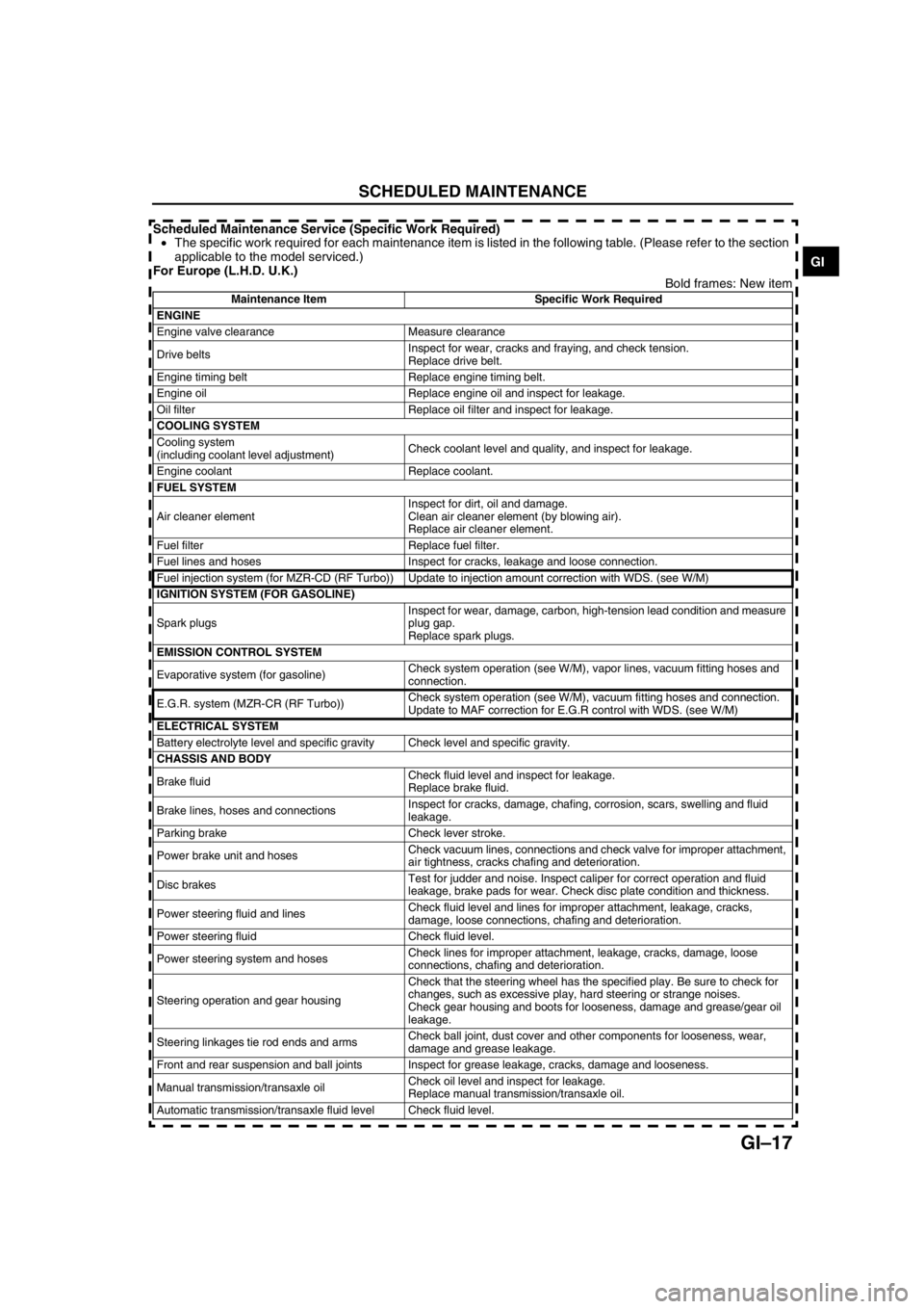
Scheduled Maintenance Service (Specific Work Required)
•The specific work required for each maintenance item is listed in the following table. (Please refer to the section
applicable to the model serviced.)
For Europe (L.H.D. U.K.)
Bold frames: New item
Maintenance Item Specific Work Required
ENGINE
Engine valve clearance Measure clearance
Drive beltsInspect for wear, cracks and fraying, and check tension.
Replace drive belt.
Engine timing belt Replace engine timing belt.
Engine oil Replace engine oil and inspect for leakage.
Oil filter Replace oil filter and inspect for leakage.
COOLING SYSTEM
Cooling system
(including coolant level adjustment)Check coolant level and quality, and inspect for leakage.
Engine coolant Replace coolant.
FUEL SYSTEM
Air cleaner elementInspect for dirt, oil and damage.
Clean air cleaner element (by blowing air).
Replace air cleaner element.
Fuel filter Replace fuel filter.
Fuel lines and hoses Inspect for cracks, leakage and loose connection.
Fuel injection system (for MZR-CD (RF Turbo)) Update to injection amount correction with WDS. (see W/M)
IGNITION SYSTEM (FOR GASOLINE)
Spark plugsInspect for wear, damage, carbon, high-tension lead condition and measure
plug gap.
Replace spark plugs.
EMISSION CONTROL SYSTEM
Evaporative system (for gasoline)Check system operation (see W/M), vapor lines, vacuum fitting hoses and
connection.
E.G.R. system (MZR-CR (RF Turbo))Check system operation (see W/M), vacuum fitting hoses and connection.
Update to MAF correction for E.G.R control with WDS. (see W/M)
ELECTRICAL SYSTEM
Battery electrolyte level and specific gravity Check level and specific gravity.
CHASSIS AND BODY
Brake fluidCheck fluid level and inspect for leakage.
Replace brake fluid.
Brake lines, hoses and connectionsInspect for cracks, damage, chafing, corrosion, scars, swelling and fluid
leakage.
Parking brake Check lever stroke.
Power brake unit and hosesCheck vacuum lines, connections and check valve for improper attachment,
air tightness, cracks chafing and deterioration.
Disc brakesTest for judder and noise. Inspect caliper for correct operation and fluid
leakage, brake pads for wear. Check disc plate condition and thickness.
Power steering fluid and linesCheck fluid level and lines for improper attachment, leakage, cracks,
damage, loose connections, chafing and deterioration.
Power steering fluid Check fluid level.
Power steering system and hosesCheck lines for improper attachment, leakage, cracks, damage, loose
connections, chafing and deterioration.
Steering operation and gear housingCheck that the steering wheel has the specified play. Be sure to check for
changes, such as excessive play, hard steering or strange noises.
Check gear housing and boots for looseness, damage and grease/gear oil
leakage.
Steering linkages tie rod ends and armsCheck ball joint, dust cover and other components for looseness, wear,
damage and grease leakage.
Front and rear suspension and ball joints Inspect for grease leakage, cracks, damage and looseness.
Manual transmission/transaxle oilCheck oil level and inspect for leakage.
Replace manual transmission/transaxle oil.
Automatic transmission/transaxle fluid level Check fluid level.
Page 32 of 909
![MAZDA 6 2002 Workshop Manual Suplement B2–1
B2
B2ENGINE [MZR-CD (RF Turbo)]
OUTLINE.............................................................. B2-2
OUTLINE OF CONSTRUCTION........................ B2-2
FEATURES ........................ MAZDA 6 2002 Workshop Manual Suplement B2–1
B2
B2ENGINE [MZR-CD (RF Turbo)]
OUTLINE.............................................................. B2-2
OUTLINE OF CONSTRUCTION........................ B2-2
FEATURES ........................](/img/28/57057/w960_57057-31.png)
B2–1
B2
B2ENGINE [MZR-CD (RF Turbo)]
OUTLINE.............................................................. B2-2
OUTLINE OF CONSTRUCTION........................ B2-2
FEATURES ........................................................ B2-2
SPECIFICATIONS ............................................. B2-2
LOCATION INDEX............................................... B2-3
LOCATION INDEX ............................................. B2-3
DRIVE BELT......................................................... B2-4
DRIVE BELT INSPECTION ............................... B2-4
DRIVE BELT REPLACEMENT .......................... B2-4
DRIVE BELT AUTO TENSIONER
INSPECTION .................................................. B2-5
VALVE CLEARANCE........................................... B2-5
VALVE CLEARANCE INSPECTION.................. B2-5
VALVE CLEARANCE ADJUSTMENT ............... B2-6
COMPRESSION PRESSURE.............................. B2-8
COMPRESSION INSPECTION ......................... B2-8
TIMING BELT....................................................... B2-9
TIMING BELT REMOVAL/INSTALLATION ....... B2-9
CYLINDER HEAD GASKET............................... B2-15
CYLINDER HEAD GASKET REPLACEMENT B2-15
FRONT OIL SEAL.............................................. B2-24
FRONT OIL SEAL REPLACEMENT ................ B2-24
REAR OIL SEAL................................................ B2-26
REAR OIL SEAL REPLACEMENT .................. B2-26
ENGINE.............................................................. B2-27
ENGINE REMOVAL/INSTALLATION .............. B2-27
ENGINE DISASSEMBLY/ASSEMBLY............. B2-32 FEATURES
SERVICE
Page 33 of 909

B2–2
OUTLINE
OUTLINE OF CONSTRUCTIONA6E230202000201•MZR-CD (RF Turbo) engine is newly adopted as Mazda6 (GG, GY).
•The construction of MZR-CD (RF Turbo) engine and operation which were newly adopted for the Mazda6 (GG,
GY) are the same as the current Mazda MPV(LW) MZR-CD (RF Turbo) engine model and current Mazda 323
(BJ) RF Turbo engine model except for the following components. (See Mazda MPV Workshop Manual
Supplement 1737-1*-02C.), (See Mazda 323 Workshop Manual Supplement 1633-10-98G.)
—Engine mount
•The construction and the operation of the engine mount for the new Mazda6 (GG, GY) MZR-CD (RF Turbo)
engine model is the same as the current Mazda6 (GG). (See Mazda6 Training Manual 3359-1*-02C)
End Of Sie
FEATURESA6E230202000202Improved engine performance
•Coated pistons have been adopted.
Reduced engine noise and vibration
•An aluminium alloy oil pan upper block has been adopted.
•An eight counter weight crankshaft has been adopted.
•A crankshaft pulley cover has been adopted.
•An engine cover with insulator has been adopted.
•A pendulum type engine mount has been adopted.
Improved serviceability
•A serpentine type drive belt has been adopted.
•An auto tensioner that automatically adjusts the drive belt tension has been adopted.
Improved design
•An engine cover has been adopted.
End Of Sie
SPECIFICATIONSA6E230202000203
End Of Sie
OUTLINE
ItemSpecifications
New Mazda6 (GG, GY) Current Mazda MPV (LW)
MZR-CD (RF Turbo) MZR-CD (RF Turbo)
TypeDiesel, 4-cycle
Cylinder arrangement and number In-line, 4-cylinder
Combustion chamber Direct injection
Valve system SOHC, belt-driven, 16-valve
Displacement (ml {cc, cu in}) 1,998 {1.998, 122.9}
Bore × stroke (mm {in}) 86.0 × 86.0 {3.39 × 3.39}
Compression ratio 18.4
Compression pressure
(kPa {kgf/cm
2, psi} [rpm])3,500 {35.7, 507.7} [250]
Valve timingINOpen BTDC (°)6
Close ABDC (°)30
EXOpen BBDC (°)41
Close ATDC (°)8
Valve clearance
[engine cold]IN (mm {in}) 0.12 —0.18 {0.005—0.007} (0.15±0.03 {0.006±0.0011})
EX (mm {in}) 0.32—0.38 {0.013—0.014} (0.35±0.03 {0.014±0.0011})
Page 34 of 909

LOCATION INDEX
B2–3
B2
LOCATION INDEXA6E230001002201
.
LOCATION INDEX
7
5
4
3
1
2
6
A6E2500W100
1Drive belt
(See B2–4 DRIVE BELT INSPECTION)
(See B2–4 DRIVE BELT REPLACEMENT)
(See B2–4 DRIVE BELT AUTO TENSIONER
INSPECTION)
2 Rocker arm
(See B2–5 VALVE CLEARANCE INSPECTION)
(See B2–6 VALVE CLEARANCE ADJUSTMENT)
3 Engine
(See B2–8 COMPRESSION INSPECTION)
(See B2–27 ENGINE REMOVAL/INSTALLATION)
(See B2–32 ENGINE DISASSEMBLY/ASSEMBLY)
4 Timing Belt
(See B2–9 TIMING BELT REMOVAL/
INSTALLATION)
5 Cylinder head gasket
(See B2–15 CYLINDER HEAD GASKET
REPLACEMENT)
6 Front oil seal
(See B2–24 FRONT OIL SEAL REPLACEMENT)
7 Rear oil seal
(See B2–26 REAR OIL SEAL REPLACEMENT)
Page 36 of 909

DRIVE BELT, VALVE CLEARANCE
B2–5
B2
3. Turn the drive belt auto tensioner pulley by hand
and verify that it rotates smoothly.
•Replace the drive belt auto tensioner if
necessary.
4. Install the drive belt.
End Of Sie
VALVE CLEARANCE INSPECTIONA6E2312121112011. Remove the engine cover. (See B2–9 TIMING BELT REMOVAL/INSTALLATION.)
2. Remove the timing belt cover bolt as shown.
3. Remove the cylinder head cover. (See B2–15
CYLINDER HEAD GASKET REPLACEMENT.)
4. Turn the crankshaft and align the timing mark so
that the piston of the No.1 or No.4 cylinder is at
TDC of compression.
5. Measure valve clearances A with the No.1
cylinder at TDC of compression, and those of B
with the No.4 cylinder at TDC of compression.
•If the valve clearance is not within the
specification, adjust the valves. (See B2–6
VALVE CLEARANCE ADJUSTMENT.)
Standard valve clearance [Engine cold]
IN: 0.12—0.18 mm {0.005—0.007 in}
(0.15±0.03 mm {0.006±0.0011 in})
EX: 0.32—0.38 mm {0.013—0.014 in}
(0.35±0.03 mm {0.014±0.0011 in})
6. Turn the crankshaft one full turn and measure the
remaining valve clearances.
•Adjust if necessary. (See B2–6 VALVE
CLEARANCE ADJUSTMENT.)
7. Install the cylinder head cover. (See B2–21 Cylinder Head Cover Installation Note.)
A6E2310W103
VALVE CLEARANCE
TIMING BELT
COVER BOLT
UPPER TIMING BELT COVER
A6E2312W200
A
A B
B
A6E2312W201
MEASURING
POINT
A6E2312W101
Page 37 of 909
B2–6
VALVE CLEARANCE
8. Install the timing belt cover bolt as shown.
Tightening torque
7.9—10.7 N·m {80—110 kgf·cm, 69.5—95.4
in·lbf}
9. Install the engine cover. (See B2–9 TIMING BELT
REMOVAL/INSTALLATION.)
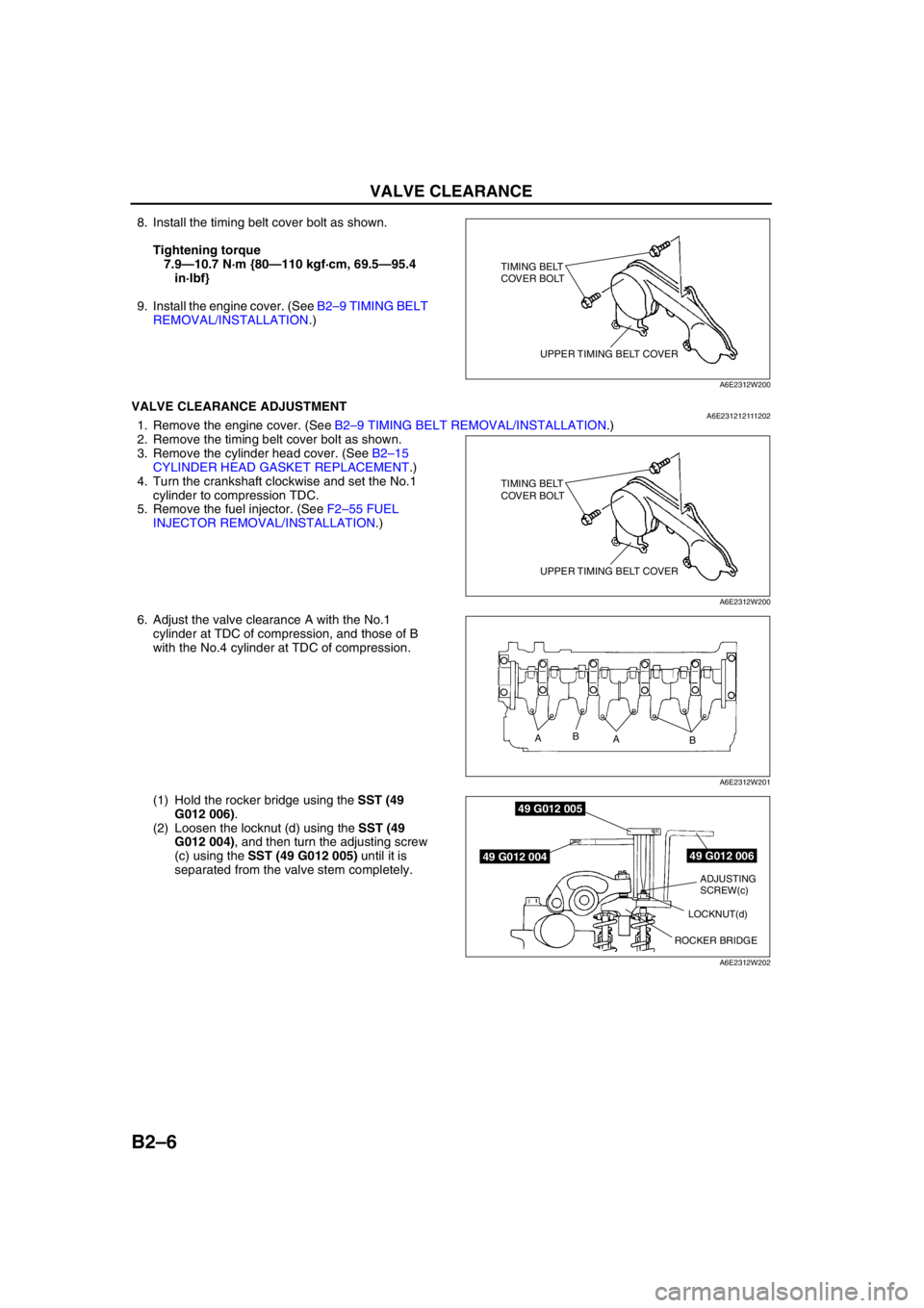
End Of SieVALVE CLEARANCE ADJUSTMENTA6E2312121112021. Remove the engine cover. (See B2–9 TIMING BELT REMOVAL/INSTALLATION.)
2. Remove the timing belt cover bolt as shown.
3. Remove the cylinder head cover. (See B2–15
CYLINDER HEAD GASKET REPLACEMENT.)
4. Turn the crankshaft clockwise and set the No.1
cylinder to compression TDC.
5. Remove the fuel injector. (See F2–55 FUEL
INJECTOR REMOVAL/INSTALLATION.)
6. Adjust the valve clearance A with the No.1
cylinder at TDC of compression, and those of B
with the No.4 cylinder at TDC of compression.
(1) Hold the rocker bridge using the SST (49
G012 006).
(2) Loosen the locknut (d) using the SST (49
G012 004), and then turn the adjusting screw
(c) using the SST (49 G012 005) until it is
separated from the valve stem completely.
TIMING BELT
COVER BOLT
UPPER TIMING BELT COVER
A6E2312W200
TIMING BELT
COVER BOLT
UPPER TIMING BELT COVER
A6E2312W200
A
A B
B
A6E2312W201
49 G012 006
49 G012 005
49 G012 004
ADJUSTING
SCREW(c)
ROCKER BRIDGELOCKNUT(d)
NORMAL
A6E2312W202
Page 39 of 909
B2–8
VALVE CLEARANCE, COMPRESSION PRESSURE
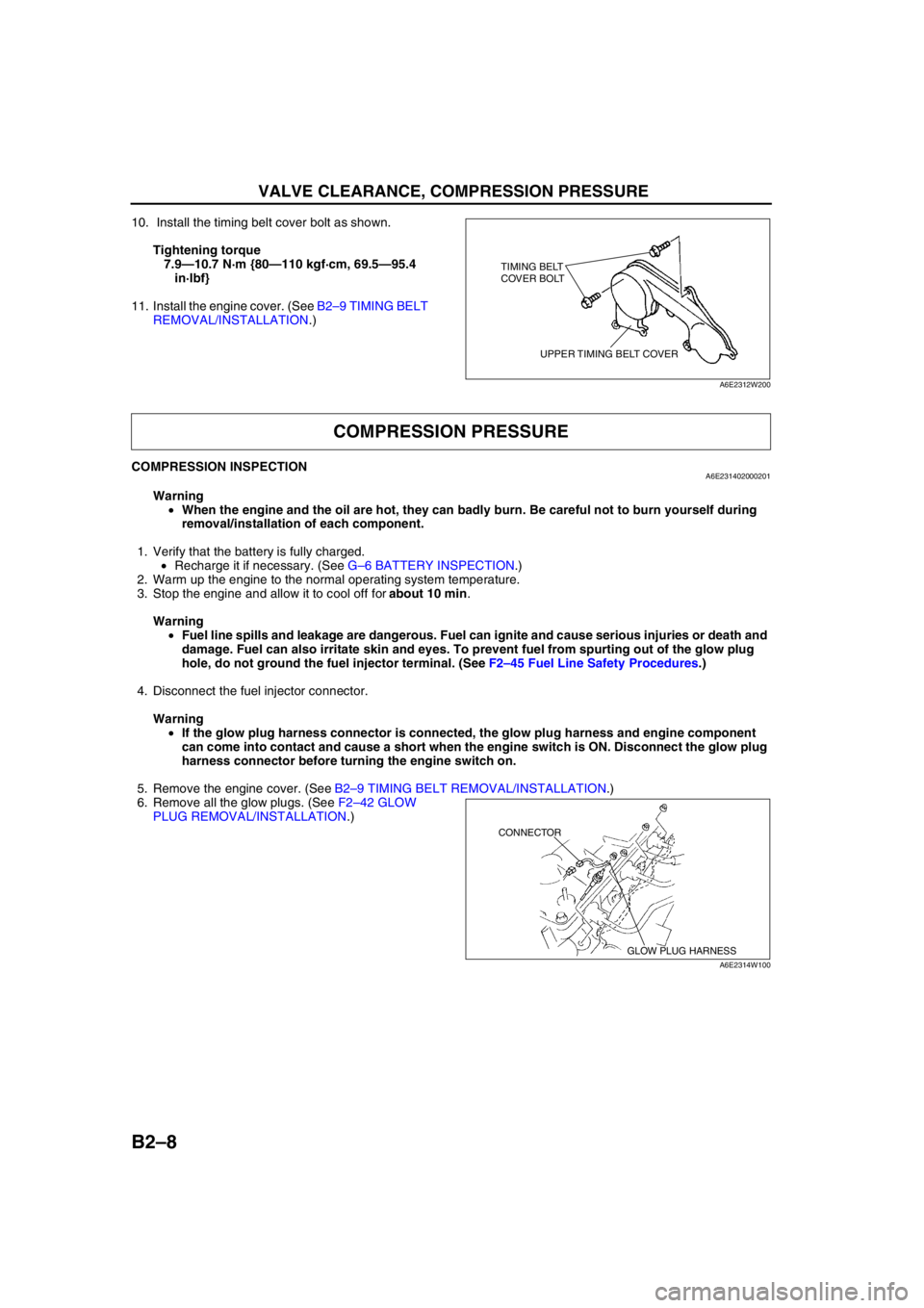
10. Install the timing belt cover bolt as shown.
Tightening torque
7.9—10.7 N·m {80—110 kgf·cm, 69.5—95.4
in·lbf}
11. Install the engine cover. (See B2–9 TIMING BELT
REMOVAL/INSTALLATION.)
End Of Sie
COMPRESSION INSPECTIONA6E231402000201
Warning
•When the engine and the oil are hot, they can badly burn. Be careful not to burn yourself during
removal/installation of each component.
1. Verify that the battery is fully charged.
•Recharge it if necessary. (See G–6 BATTERY INSPECTION.)
2. Warm up the engine to the normal operating system temperature.
3. Stop the engine and allow it to cool off for about 10 min.
Warning
•Fuel line spills and leakage are dangerous. Fuel can ignite and cause serious injuries or death and
damage. Fuel can also irritate skin and eyes. To prevent fuel from spurting out of the glow plug
hole, do not ground the fuel injector terminal. (See F2–45 Fuel Line Safety Procedures.)
4. Disconnect the fuel injector connector.
Warning
•If the glow plug harness connector is connected, the glow plug harness and engine component
can come into contact and cause a short when the engine switch is ON. Disconnect the glow plug
harness connector before turning the engine switch on.
5. Remove the engine cover. (See B2–9 TIMING BELT REMOVAL/INSTALLATION.)
6. Remove all the glow plugs. (See F2–42 GLOW
PLUG REMOVAL/INSTALLATION.)
TIMING BELT
COVER BOLT
UPPER TIMING BELT COVER
A6E2312W200
COMPRESSION PRESSURE
GLOW PLUG HARNESS CONNECTOR
A6E2314W100
Page 40 of 909
COMPRESSION PRESSURE, TIMING BELT
B2–9
B2
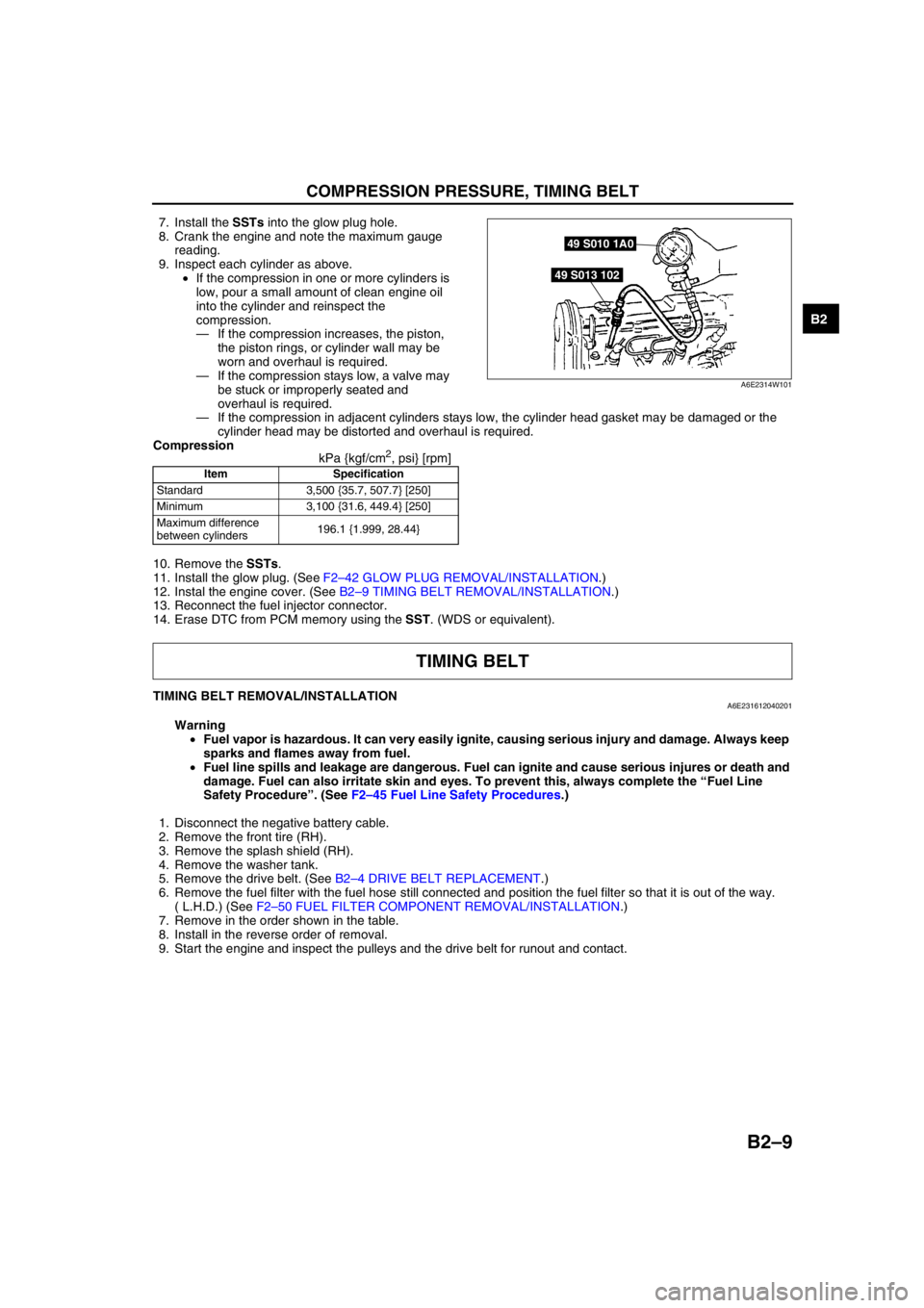
7. Install the SSTs into the glow plug hole.
8. Crank the engine and note the maximum gauge
reading.
9. Inspect each cylinder as above.
•If the compression in one or more cylinders is
low, pour a small amount of clean engine oil
into the cylinder and reinspect the
compression.
—If the compression increases, the piston,
the piston rings, or cylinder wall may be
worn and overhaul is required.
—If the compression stays low, a valve may
be stuck or improperly seated and
overhaul is required.
—If the compression in adjacent cylinders stays low, the cylinder head gasket may be damaged or the
cylinder head may be distorted and overhaul is required.
Compression
kPa {kgf/cm
2, psi} [rpm]
10. Remove the SSTs.
11. Install the glow plug. (See F2–42 GLOW PLUG REMOVAL/INSTALLATION.)
12. Instal the engine cover. (See B2–9 TIMING BELT REMOVAL/INSTALLATION.)
13. Reconnect the fuel injector connector.
14. Erase DTC from PCM memory using the SST. (WDS or equivalent).
End Of Sie
TIMING BELT REMOVAL/INSTALLATIONA6E231612040201
Warning
•Fuel vapor is hazardous. It can very easily ignite, causing serious injury and damage. Always keep
sparks and flames away from fuel.
•Fuel line spills and leakage are dangerous. Fuel can ignite and cause serious injures or death and
damage. Fuel can also irritate skin and eyes. To prevent this, always complete the “Fuel Line
Safety Procedure”. (See F2–45 Fuel Line Safety Procedures.)
1. Disconnect the negative battery cable.
2. Remove the front tire (RH).
3. Remove the splash shield (RH).
4. Remove the washer tank.
5. Remove the drive belt. (See B2–4 DRIVE BELT REPLACEMENT.)
6. Remove the fuel filter with the fuel hose still connected and position the fuel filter so that it is out of the way.
( L.H.D.) (See F2–50 FUEL FILTER COMPONENT REMOVAL/INSTALLATION.)
7. Remove in the order shown in the table.
8. Install in the reverse order of removal.
9. Start the engine and inspect the pulleys and the drive belt for runout and contact.
Item Specification
Standard 3,500 {35.7, 507.7} [250]
Minimum 3,100 {31.6, 449.4} [250]
Maximum difference
between cylinders196.1 {1.999, 28.44}
49 S010 1A0
49 S013 102
A6E2314W101
TIMING BELT