clock MAZDA 6 2002 Workshop Manual Suplement
[x] Cancel search | Manufacturer: MAZDA, Model Year: 2002, Model line: 6, Model: MAZDA 6 2002Pages: 909, PDF Size: 17.16 MB
Page 35 of 909
B2–4
DRIVE BELT
End Of Sie
DRIVE BELT INSPECTIONA6E231015800201
Note
•Drive belt deflection/tension inspection is not necessary because of the use of the drive belt auto
tensioner.
1. Remove the washer tank.
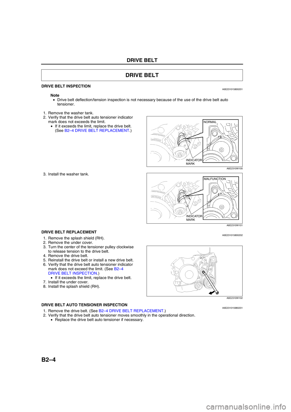
2. Verify that the drive belt auto tensioner indicator
mark does not exceeds the limit.
•If it exceeds the limit, replace the drive belt.
(See B2–4 DRIVE BELT REPLACEMENT.)
3. Install the washer tank.
End Of SieDRIVE BELT REPLACEMENTA6E2310158002021. Remove the splash shield (RH).
2. Remove the under cover.
3. Turn the center of the tensioner pulley clockwise
to release tension to the drive belt.
4. Remove the drive belt.
5. Reinstall the drive belt or install a new drive belt.
6. Verify that the drive belt auto tensioner indicator
mark does not exceed the limit. (See B2–4
DRIVE BELT INSPECTION.)
•If it exceeds the limit, replace the drive belt.
7. Install the under cover.
8. Install the splash shield (RH).
End Of SieDRIVE BELT AUTO TENSIONER INSPECTIONA6E2310159802011. Remove the drive belt. (See B2–4 DRIVE BELT REPLACEMENT.)
2. Verify that the drive belt auto tensioner moves smoothly in the operational direction.
•Replace the drive belt auto tensioner if necessary.
DRIVE BELT
INDICATOR
MARKNORMAL
A6E2310W100
MALFUNCTION
INDICATOR
MARK
A6E2310W101
A6E2310W102
Page 37 of 909
B2–6
VALVE CLEARANCE
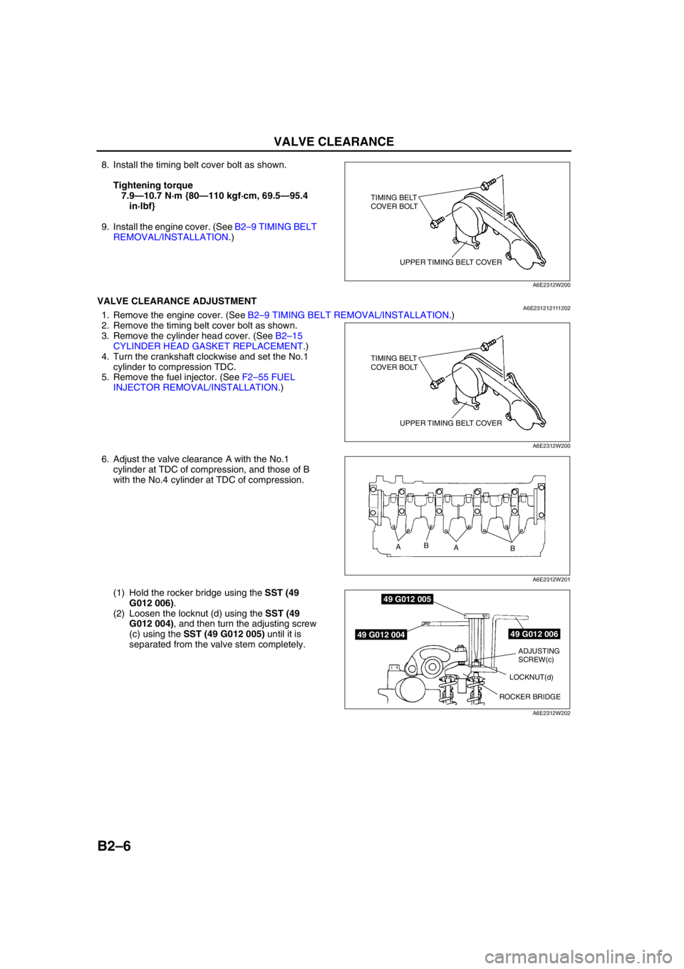
8. Install the timing belt cover bolt as shown.
Tightening torque
7.9—10.7 N·m {80—110 kgf·cm, 69.5—95.4
in·lbf}
9. Install the engine cover. (See B2–9 TIMING BELT
REMOVAL/INSTALLATION.)
End Of SieVALVE CLEARANCE ADJUSTMENTA6E2312121112021. Remove the engine cover. (See B2–9 TIMING BELT REMOVAL/INSTALLATION.)
2. Remove the timing belt cover bolt as shown.
3. Remove the cylinder head cover. (See B2–15
CYLINDER HEAD GASKET REPLACEMENT.)
4. Turn the crankshaft clockwise and set the No.1
cylinder to compression TDC.
5. Remove the fuel injector. (See F2–55 FUEL
INJECTOR REMOVAL/INSTALLATION.)
6. Adjust the valve clearance A with the No.1
cylinder at TDC of compression, and those of B
with the No.4 cylinder at TDC of compression.
(1) Hold the rocker bridge using the SST (49
G012 006).
(2) Loosen the locknut (d) using the SST (49
G012 004), and then turn the adjusting screw
(c) using the SST (49 G012 005) until it is
separated from the valve stem completely.
TIMING BELT
COVER BOLT
UPPER TIMING BELT COVER
A6E2312W200
TIMING BELT
COVER BOLT
UPPER TIMING BELT COVER
A6E2312W200
A
A B
B
A6E2312W201
49 G012 006
49 G012 005
49 G012 004
ADJUSTING
SCREW(c)
ROCKER BRIDGELOCKNUT(d)
NORMAL
A6E2312W202
Page 42 of 909
TIMING BELT
B2–11
B2
No.3 Engine Joint Bracket Removal Note
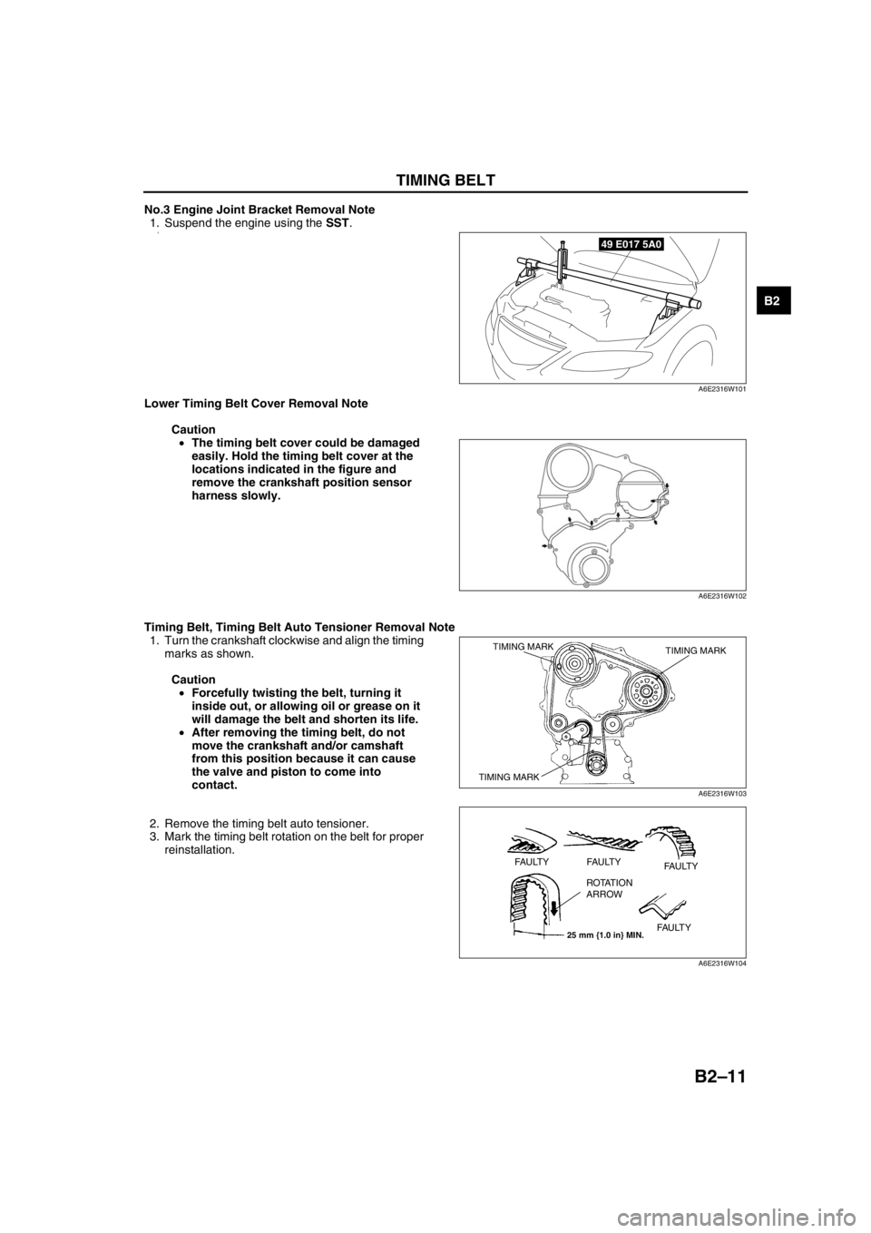
1. Suspend the engine using the SST.
2.
Lower Timing Belt Cover Removal Note
Caution
•The timing belt cover could be damaged
easily. Hold the timing belt cover at the
locations indicated in the figure and
remove the crankshaft position sensor
harness slowly.
Timing Belt, Timing Belt Auto Tensioner Removal Note
1. Turn the crankshaft clockwise and align the timing
marks as shown.
Caution
•Forcefully twisting the belt, turning it
inside out, or allowing oil or grease on it
will damage the belt and shorten its life.
•After removing the timing belt, do not
move the crankshaft and/or camshaft
from this position because it can cause
the valve and piston to come into
contact.
2. Remove the timing belt auto tensioner.
3. Mark the timing belt rotation on the belt for proper
reinstallation.
49 E017 5A0
A6E2316W101
A6E2316W102
TIMING MARK TIMING MARK
TIMING MARK
A6E2316W103
25 mm {1.0 in} MIN.
FAULTY FAULTY
FAULTY
FAULTY ROTATION
ARROW
A6E2316W104
Page 44 of 909
TIMING BELT
B2–13
B2
Caution
•To prevent the bolts (M8 x 1.25) from damaging the fuel injection pump and pulley, do not fully
tighten the fixing bolts. If it contacts the pulley surface, it will damage the pulley.
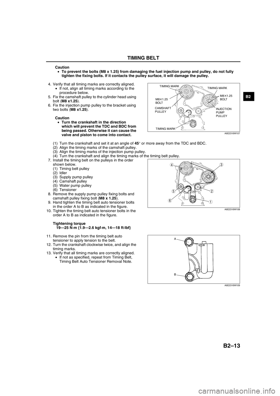
4. Verify that all timing marks are correctly aligned.
•If not, align all timing marks according to the
procedure below.
5. Fix the camshaft pulley to the cylinder head using
bolt (M8 x1.25).
6. Fix the injection pump pulley to the bracket using
two bolts (M8 x1.25).
Caution
•Turn the crankshaft in the direction
which will prevent the TDC and BDC from
being passed. Otherwise it can cause the
valve and piston to come into contact.
(1) Turn the crankshaft and set it at an angle of 45° or more away from the TDC and BDC.
(2) Align the timing marks of the camshaft pulley.
(3) Align the timing marks of the injection pump pulley.
(4) Turn the crankshaft and align the timing marks of the timing belt pulley.
7. Install the timing belt on the pulleys in the order
shown below.
(1) Timing belt pulley
(2) Idler
(3) Supply pump pulley
(4) Camshaft pulley
(5) Water pump pulley
(6) Tensioner
8. Remove the supply pump pulley fixing bolts and
camshaft pulley fixing bolt (M8 x 1.25).
9. Hand tighten the timing belt auto tensioner bolts
in the order A to B as indicated in the figure.
10. Tighten the timing belt auto tensioner bolts in the
order A to B as indicated in the figure.
Tightening torque
19—25 N·m {1.9—2.6 kgf·m, 14—18 ft·lbf}
11. Remove the pin from the timing belt auto
tensioner to apply tension to the belt.
12. Turn the crankshaft clockwise twice, and align the
timing marks.
13. Verify that all timing marks are correctly aligned.
•If not as specified, repeat from Timing Belt,
Timing Belt Auto Tensioner Removal Note.
TIMING MARK
TIMING MARKTIMING MARK
M8 1.25
BOLT
M8 1.25
BOLT
CAMSHAFT
PULLEYINJECTION
PUMP
PULLEY
A6E2316W107
5
43
1
2
6
A6E2316W108
A
B
A6E2316W109
Page 53 of 909
B2–22
CYLINDER HEAD GASKET
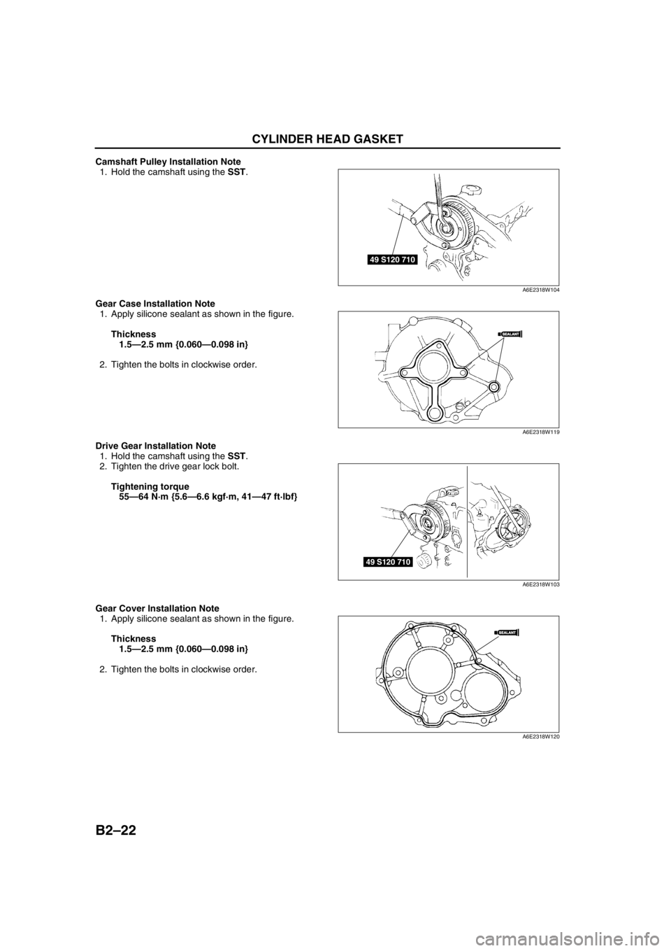
Camshaft Pulley Installation Note
1. Hold the camshaft using the SST.
Gear Case Installation Note
1. Apply silicone sealant as shown in the figure.
Thickness
1.5—2.5 mm {0.060—0.098 in}
2. Tighten the bolts in clockwise order.
Drive Gear Installation Note
1. Hold the camshaft using the SST.
2. Tighten the drive gear lock bolt.
Tightening torque
55—64 N·m {5.6—6.6 kgf·m, 41—47 ft·lbf}
Gear Cover Installation Note
1. Apply silicone sealant as shown in the figure.
Thickness
1.5—2.5 mm {0.060—0.098 in}
2. Tighten the bolts in clockwise order.
49 S120 710
A6E2318W104
SEALANTSEALANT
A6E2318W119
49 S120 710
A6E2318W103
SEALANTSEALANT
A6E2318W120
Page 82 of 909
RADIATOR CAP
E–7
E
RADIATOR CAP INSPECTIONA6E361415201201MZR-CD (RF Turbo)
Warning
•Never remove the radiator cap while the engine is running, or when the engine and radiator are
hot. Scalding coolant and steam may shoot out and cause serious injury. It may also damage the
engine and cooling system.
•Turn off the engine and wait until it is cool. Even then, be very careful when removing the cap.
Wrap a thick cloth around it and slowly turn it counterclockwise to the first stop. Step back while
the pressure escapes.
•When you are sure all the pressure is gone, press down on the cap using the cloth, turn it, and
remove it.
1. Clean the radiator cap negative pressure valve and the sealed part.
2. Inspect the crack or turn over on the sealed part of the radiator cap.
•If not as specified, repace the radiator cap.
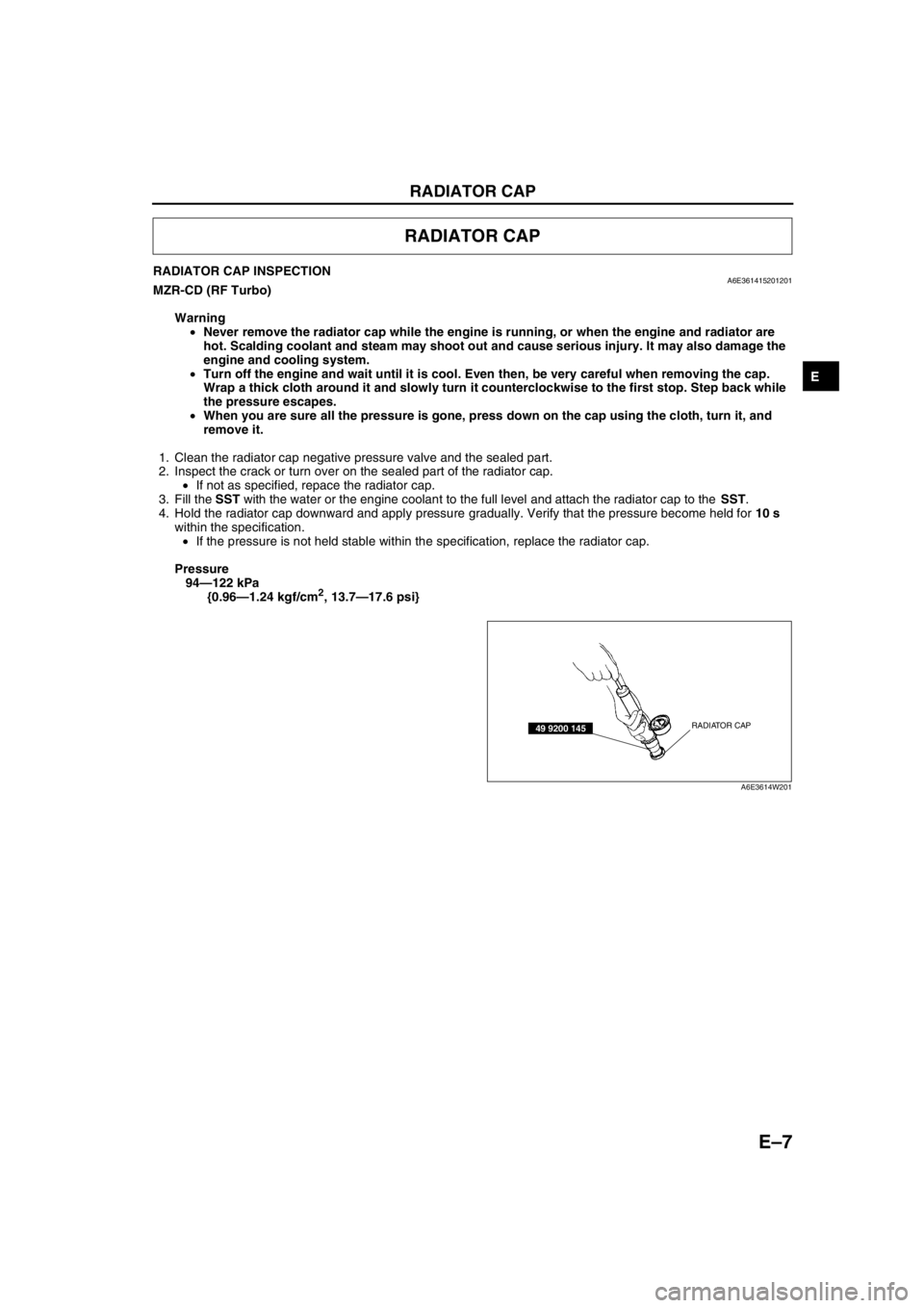
3. Fill the SST with the water or the engine coolant to the full level and attach the radiator cap to the SST.
4. Hold the radiator cap downward and apply pressure gradually. Verify that the pressure become held for 10 s
within the specification.
•If the pressure is not held stable within the specification, replace the radiator cap.
Pressure
94—122 kPa
{0.96—1.24 kgf/cm
2, 13.7—17.6 psi}
End Of Sie
RADIATOR CAP
RADIATOR CAP49 9200 145
A6E3614W201
Page 83 of 909
E–8
ENGINE COOLANT
ENGINE COOLANT LEAKAGE INSPECTIONA6E361215201201MZR-CD (RF Turbo)
Warning
•Never remove the radiator cap while the engine is running, or when the engine and radiator are
hot. Scalding coolant and steam may shoot out and cause serious injury. It may also damage the
engine and cooling system.
•Turn off the engine and wait until it is cool. Even then, be very careful when removing the cap.
Wrap a thick cloth around it and slowly turn it counterclockwise to the first stop. Step back while
the pressure escapes.
•When you are sure all the pressure is gone, press down on the cap using the cloth, turn it, and
remove it.
1. Inspect the coolant level.
2. Remove the radiator cap.
3. Clean the mounting surface of the rediator cap and the upper radiator hose.
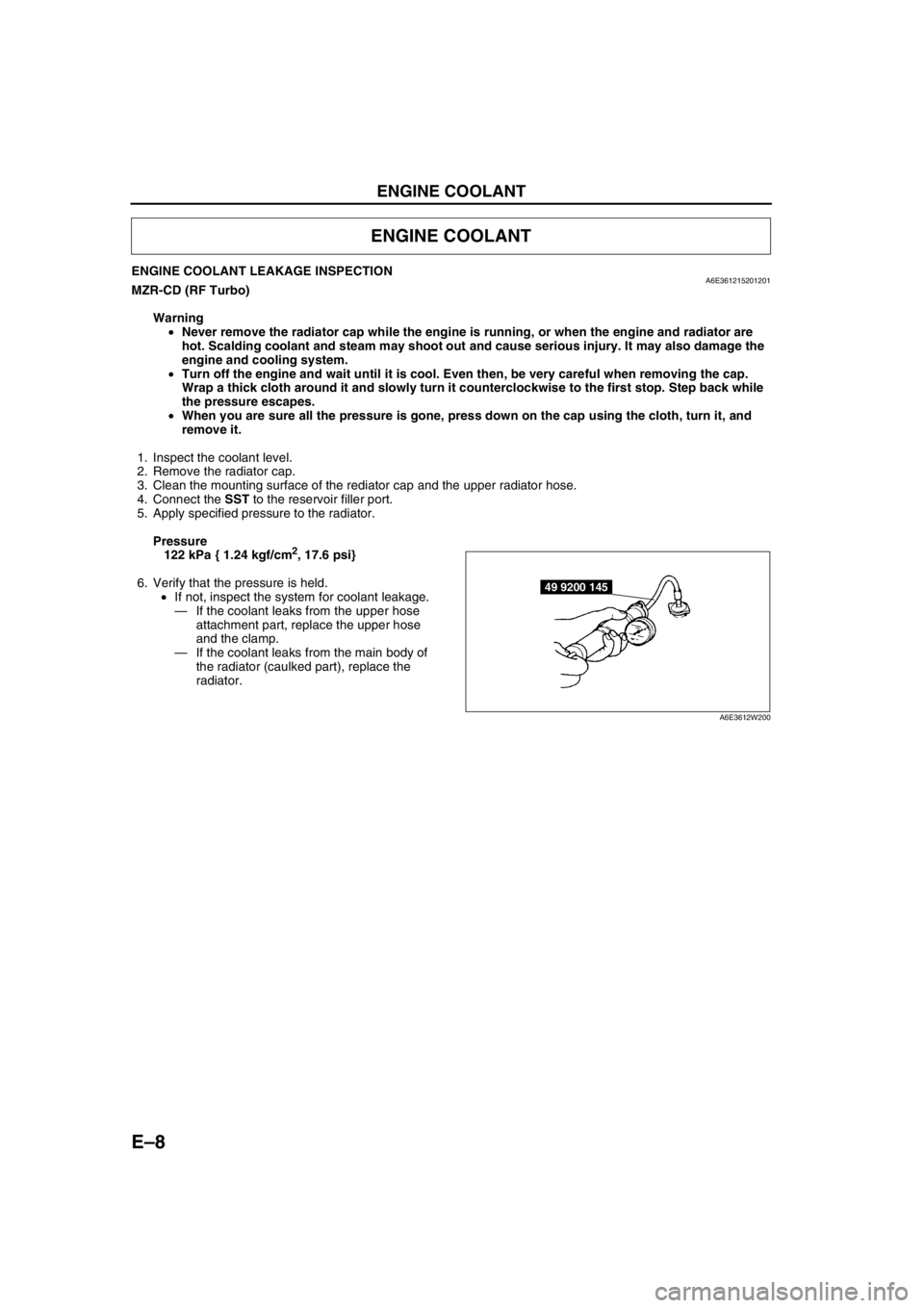
4. Connect the SST to the reservoir filler port.
5. Apply specified pressure to the radiator.
Pressure
122 kPa { 1.24 kgf/cm
2, 17.6 psi}
6. Verify that the pressure is held.
•If not, inspect the system for coolant leakage.
—If the coolant leaks from the upper hose
attachment part, replace the upper hose
and the clamp.
—If the coolant leaks from the main body of
the radiator (caulked part), replace the
radiator.
End Of Sie
ENGINE COOLANT
49 9200 145
A6E3612W200
Page 432 of 909
AUTOMATIC TRANSAXLE
K2–17
K2
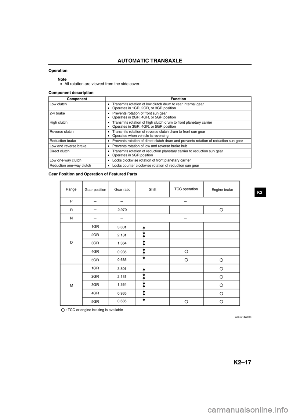
Operation
Note
•All rotation are viewed from the side cover.
Component description
Gear Position and Operation of Featured Parts
Component Function
Low clutch•Transmits rotation of low clutch drum to rear internal gear
•Operates in 1GR, 2GR, or 3GR position
2-4 brake•Prevents rotation of front sun gear
•Operates in 2GR, 4GR, or 5GR position
High clutch•Transmits rotation of high clutch drum to front planetary carrier
•Operates in 3GR, 4GR, or 5GR position
Reverse clutch•Transmits rotation of reverse clutch drum to front sun gear
•Operates when vehicle is reversing
Reduction brake•Prevents rotation of direct clutch drum and prevents rotation of reduction sun gear
Low and reverse brake•Prevents rotation of low and reverse brake hub
Direct clutch•Transmits rotation of reduction planetary carrier to reduction sun gear
•Operates in 5GR position
Low one-way clutch•Locks clockwise rotation of front planetary carrier
Reduction one-way clutch•Locks counter clockwise rotation of reduction sun gear
Range
P
R
N
D1GR
2GR
3GR
4GR
5GR
1GR
2GR
3GR
4GR
5GR
: TCC or engine braking is availableMGear positionGear ratioTCC operation
Engine brake Shift
2.970
3.801
2.131
1.364
0.935
0.685
3.801
2.131
1.364
0.935
0.685
A6E5714W013
Page 771 of 909
WHEEL ALIGNMENT
R–9
R
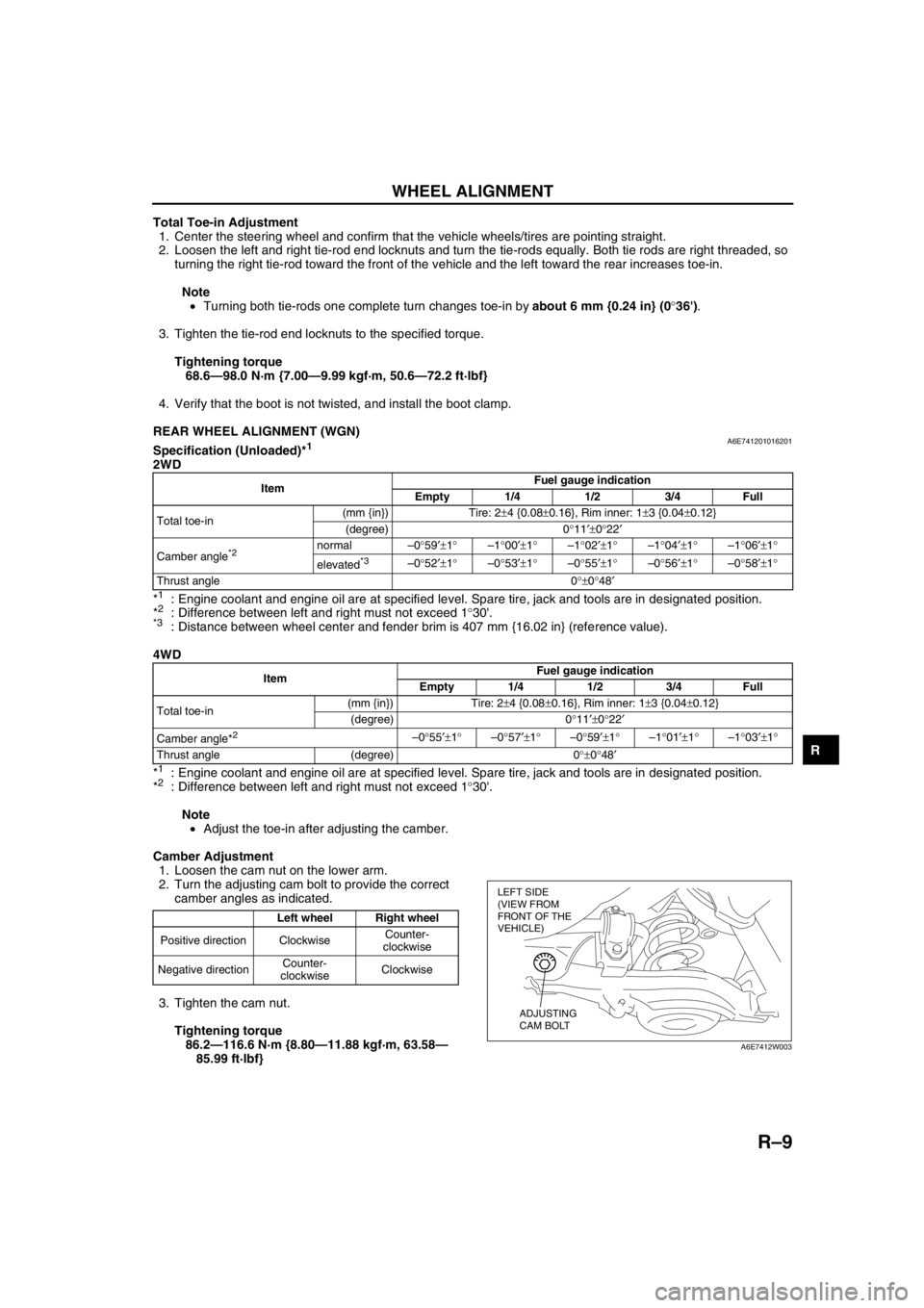
Total Toe-in Adjustment
1. Center the steering wheel and confirm that the vehicle wheels/tires are pointing straight.
2. Loosen the left and right tie-rod end locknuts and turn the tie-rods equally. Both tie rods are right threaded, so
turning the right tie-rod toward the front of the vehicle and the left toward the rear increases toe-in.
Note
•Turning both tie-rods one complete turn changes toe-in by about 6 mm {0.24 in} (0°36').
3. Tighten the tie-rod end locknuts to the specified torque.
Tightening torque
68.6—98.0 N·m {7.00—9.99 kgf·m, 50.6—72.2 ft·lbf}
4. Verify that the boot is not twisted, and install the boot clamp.
End Of Sie
REAR WHEEL ALIGNMENT (WGN)A6E741201016201Specification (Unloaded)*1
2WD
*
1: Engine coolant and engine oil are at specified level. Spare tire, jack and tools are in designated position.
*2: Difference between left and right must not exceed 1°30'.*3: Distance between wheel center and fender brim is 407 mm {16.02 in} (reference value).
4WD
*
1: Engine coolant and engine oil are at specified level. Spare tire, jack and tools are in designated position.
*2: Difference between left and right must not exceed 1°30'.
Note
•Adjust the toe-in after adjusting the camber.
Camber Adjustment
1. Loosen the cam nut on the lower arm.
2. Turn the adjusting cam bolt to provide the correct
camber angles as indicated.
3. Tighten the cam nut.
Tightening torque
86.2—116.6 N·m {8.80—11.88 kgf·m, 63.58—
85.99 ft·lbf}
ItemFuel gauge indication
Empty 1/4 1/2 3/4 Full
Total toe-in(mm {in}) Tire: 2±4 {0.08±0.16}, Rim inner: 1±3 {0.04±0.12}
(degree) 0°11′±0°22′
Camber angle
*2 normal–0°59′±1°–1°00′±1°–1°02′±1°–1°04′±1°–1°06′±1°
elevated
*3–0°52′±1°–0°53′±1°–0°55′±1°–0°56′±1°–0°58′±1°
Thrust angle 0°±0°48′
ItemFuel gauge indication
Empty 1/4 1/2 3/4 Full
Total toe-in(mm {in}) Tire: 2±4 {0.08±0.16}, Rim inner: 1±3 {0.04±0.12}
(degree) 0°11′±0°22′
Camber angle*
2 –0°55′±1°–0°57′±1°–0°59′±1°–1°01′±1°–1°03′±1°
Thrust angle (degree) 0°±0°48′
Left wheel Right wheel
Positive direction ClockwiseCounter-
clockwise
Negative directionCounter-
clockwiseClockwise
LEFT SIDE
(VIEW FROM
FRONT OF THE
VEHICLE)
ADJUSTING
CAM BOLT
A6E7412W003
Page 896 of 909
TD–4
TECHNICAL DATA
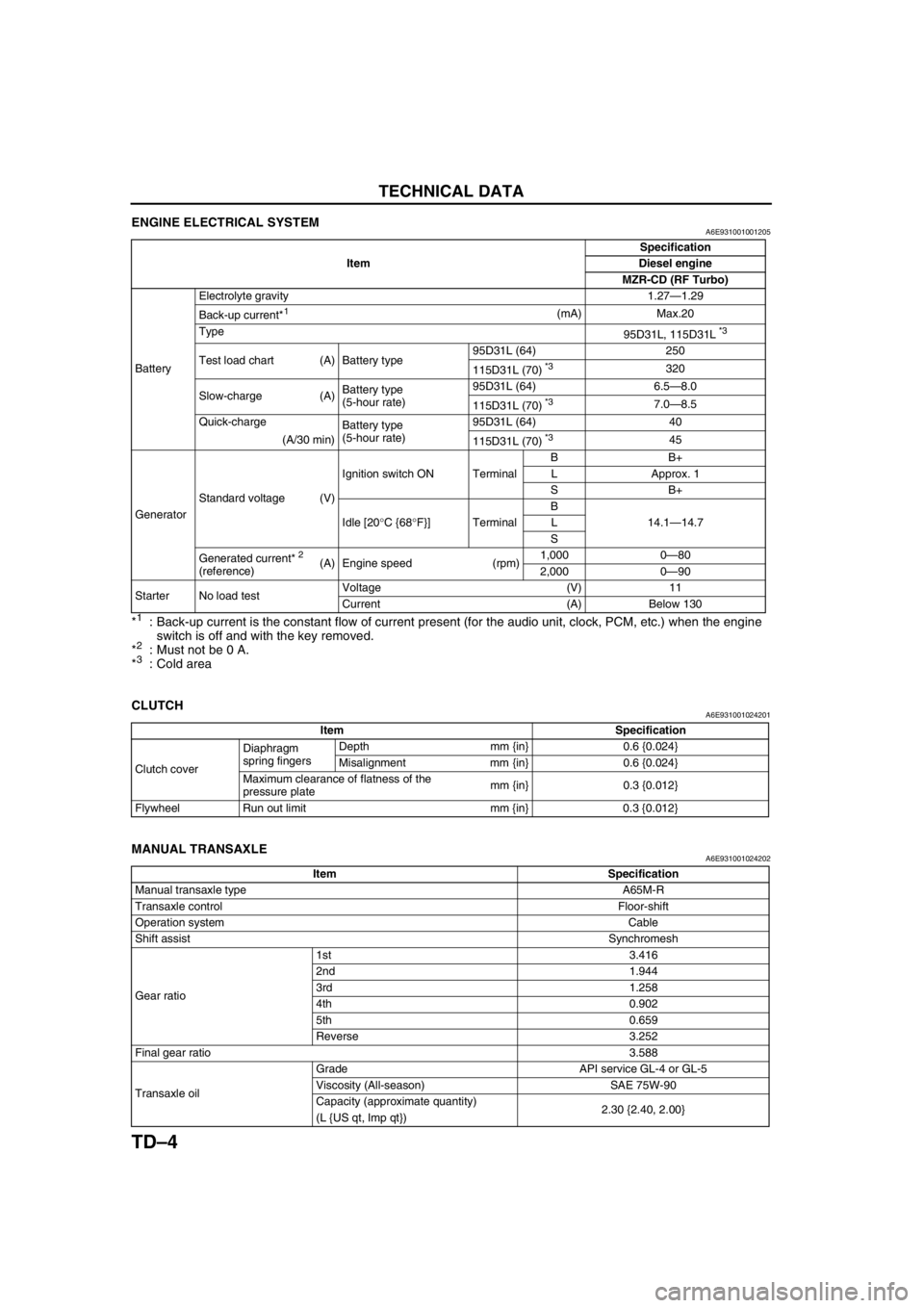
ENGINE ELECTRICAL SYSTEMA6E931001001205
*1: Back-up current is the constant flow of current present (for the audio unit, clock, PCM, etc.) when the engine
switch is off and with the key removed.
*
2: Must not be 0 A.
*3: Cold area
End Of Sie
CLUTCHA6E931001024201
End Of Sie
MANUAL TRANSAXLEA6E931001024202
ItemSpecification
Diesel engine
MZR-CD (RF Turbo)
BatteryElectrolyte gravity 1.27—1.29
Back-up current*
1(mA) Max.20
Type
95D31L, 115D31L
*3
Test load chart (A) Battery type95D31L (64) 250
115D31L (70) *3320
Slow-charge (A)Battery type
(5-hour rate)95D31L (64) 6.5—8.0
115D31L (70)
*37.0—8.5
Quick-charge
Battery type
(5-hour rate)95D31L (64) 40
(A/30 min)
115D31L (70)
*345
GeneratorStandard voltage (V)Ignition switch ON TerminalBB+
L Approx. 1
SB+
Idle [20°C {68°F}] TerminalB
14.1—14.7 L
S
Generated current*
2
(reference) (A) Engine speed (rpm)1,000 0—80
2,000 0—90
Starter No load testVoltage (V) 11
Current (A) Below 130
Item Specification
Clutch coverDiaphragm
spring fingersDepth mm {in} 0.6 {0.024}
Misalignment mm {in} 0.6 {0.024}
Maximum clearance of flatness of the
pressure platemm {in} 0.3 {0.012}
Flywheel Run out limit mm {in} 0.3 {0.012}
Item Specification
Manual transaxle typeA65M-R
Transaxle controlFloor-shift
Operation systemCable
Shift assistSynchromesh
Gear ratio1st 3.416
2nd 1.944
3rd 1.258
4th 0.902
5th 0.659
Reverse 3.252
Final gear ratio3.588
Transaxle oilGrade API service GL-4 or GL-5
Viscosity (All-season) SAE 75W-90
Capacity (approximate quantity)
2.30 {2.40, 2.00}
(L {US qt, Imp qt})