tire type MAZDA 6 2002 Workshop Manual Suplement
[x] Cancel search | Manufacturer: MAZDA, Model Year: 2002, Model line: 6, Model: MAZDA 6 2002Pages: 909, PDF Size: 17.16 MB
Page 109 of 909

CONTROL SYSTEM
F1–21
F1
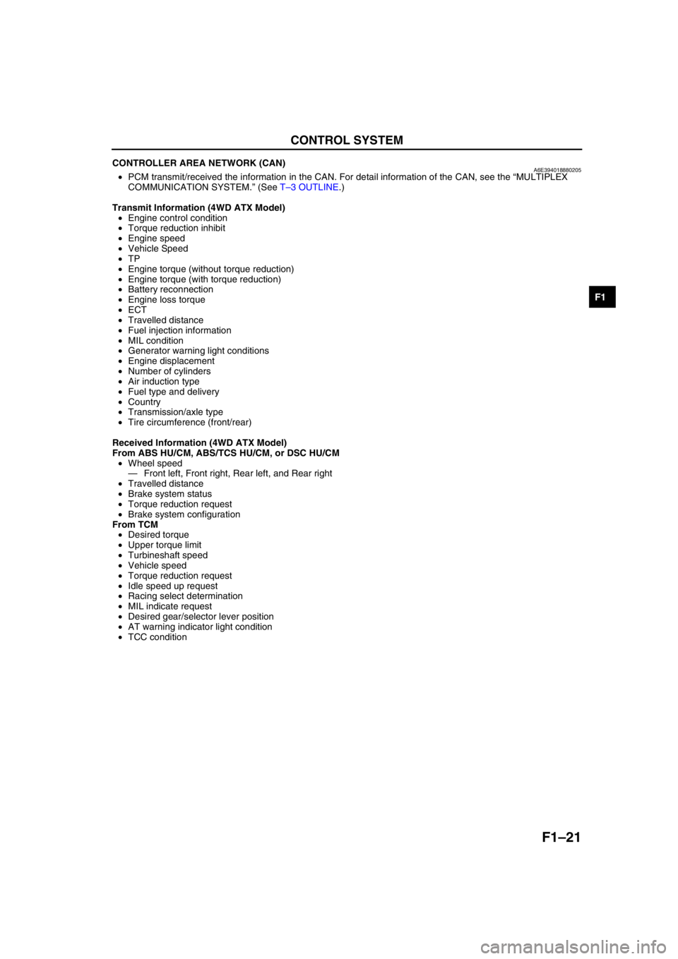
CONTROLLER AREA NETWORK (CAN)A6E394018880205•PCM transmit/received the information in the CAN. For detail information of the CAN, see the “MULTIPLEX
COMMUNICATION SYSTEM.” (See T–3 OUTLINE.)
Transmit Information (4WD ATX Model)
•Engine control condition
•Torque reduction inhibit
•Engine speed
•Vehicle Speed
•TP
•Engine torque (without torque reduction)
•Engine torque (with torque reduction)
•Battery reconnection
•Engine loss torque
•ECT
•Travelled distance
•Fuel injection information
•MIL condition
•Generator warning light conditions
•Engine displacement
•Number of cylinders
•Air induction type
•Fuel type and delivery
•Country
•Transmission/axle type
•Tire circumference (front/rear)
Received Information (4WD ATX Model)
From ABS HU/CM, ABS/TCS HU/CM, or DSC HU/CM
•Wheel speed
—Front left, Front right, Rear left, and Rear right
•Travelled distance
•Brake system status
•Torque reduction request
•Brake system configuration
From TCM
•Desired torque
•Upper torque limit
•Turbineshaft speed
•Vehicle speed
•Torque reduction request
•Idle speed up request
•Racing select determination
•MIL indicate request
•Desired gear/selector lever position
•AT warning indicator light condition
•TCC condition
End Of Sie
Page 176 of 909

F2–24
CONTROL SYSTEM, ON-BOARD DIAGNOSTIC
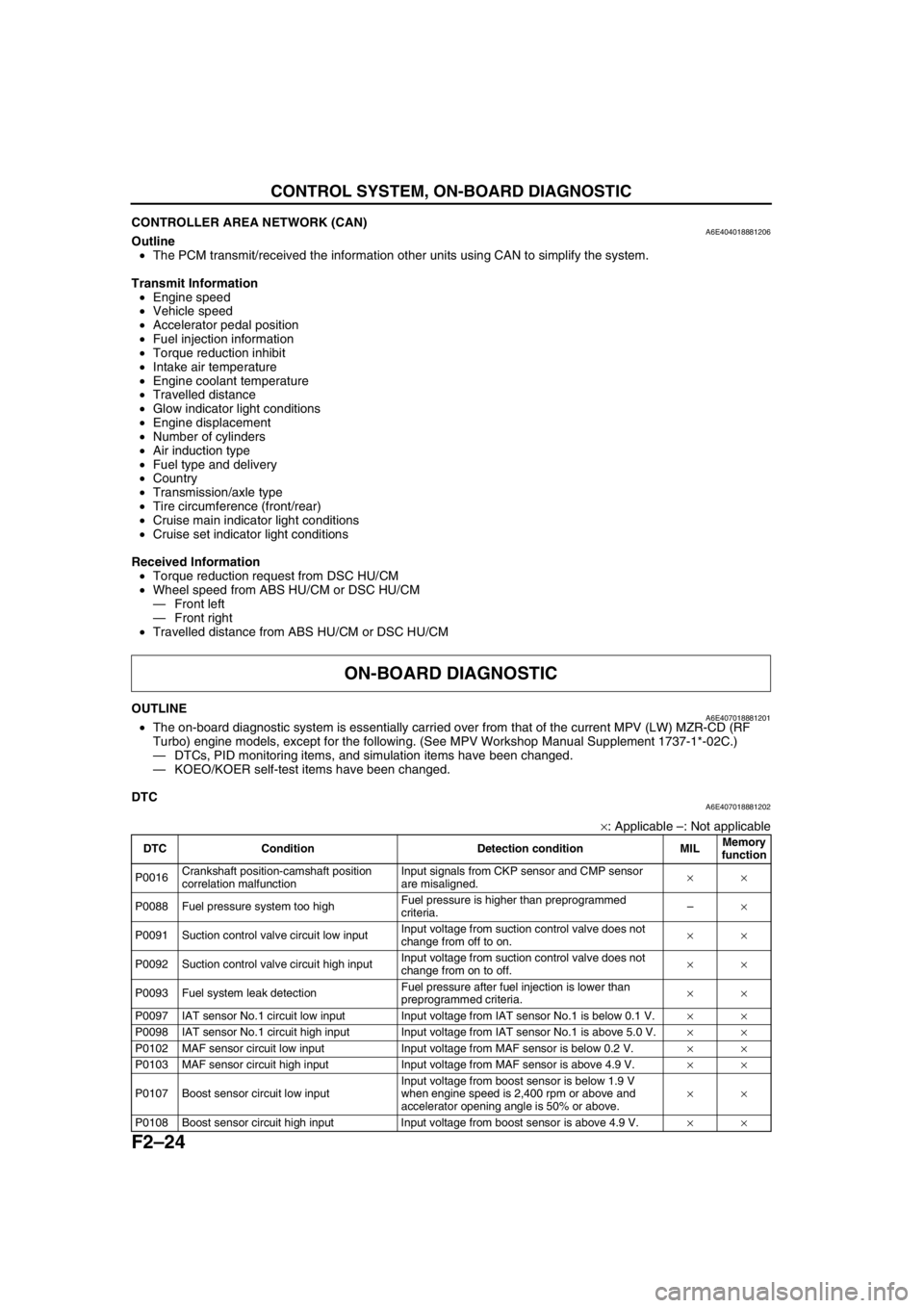
CONTROLLER AREA NETWORK (CAN)A6E404018881206Outline
•The PCM transmit/received the information other units using CAN to simplify the system.
Transmit Information
•Engine speed
•Vehicle speed
•Accelerator pedal position
•Fuel injection information
•Torque reduction inhibit
•Intake air temperature
•Engine coolant temperature
•Travelled distance
•Glow indicator light conditions
•Engine displacement
•Number of cylinders
•Air induction type
•Fuel type and delivery
•Country
•Transmission/axle type
•Tire circumference (front/rear)
•Cruise main indicator light conditions
•Cruise set indicator light conditions
Received Information
•Torque reduction request from DSC HU/CM
•Wheel speed from ABS HU/CM or DSC HU/CM
—Front left
—Front right
•Travelled distance from ABS HU/CM or DSC HU/CM
End Of Sie
OUTLINEA6E407018881201•The on-board diagnostic system is essentially carried over from that of the current MPV (LW) MZR-CD (RF
Turbo) engine models, except for the following. (See MPV Workshop Manual Supplement 1737-1*-02C.)
—DTCs, PID monitoring items, and simulation items have been changed.
—KOEO/KOER self-test items have been changed.
End Of Sie
DTCA6E407018881202
×: Applicable –: Not applicable
ON-BOARD DIAGNOSTIC
DTC Condition Detection condition MILMemory
function
P0016Crankshaft position-camshaft position
correlation malfunctionInput signals from CKP sensor and CMP sensor
are misaligned.××
P0088 Fuel pressure system too highFuel pressure is higher than preprogrammed
criteria.–×
P0091 Suction control valve circuit low inputInput voltage from suction control valve does not
change from off to on.××
P0092 Suction control valve circuit high inputInput voltage from suction control valve does not
change from on to off.××
P0093 Fuel system leak detectionFuel pressure after fuel injection is lower than
preprogrammed criteria.××
P0097 IAT sensor No.1 circuit low input Input voltage from IAT sensor No.1 is below 0.1 V.××
P0098 IAT sensor No.1 circuit high input Input voltage from IAT sensor No.1 is above 5.0 V.××
P0102 MAF sensor circuit low input Input voltage from MAF sensor is below 0.2 V.××
P0103 MAF sensor circuit high input Input voltage from MAF sensor is above 4.9 V.××
P0107 Boost sensor circuit low inputInput voltage from boost sensor is below 1.9 V
when engine speed is 2,400 rpm or above and
accelerator opening angle is 50% or above.××
P0108 Boost sensor circuit high input Input voltage from boost sensor is above 4.9 V.××
Page 419 of 909

K2–4
AUTOMATIC TRANSAXLE
Bold frames:New specifications
End Of Sie
OUTLINEA6E571401030201•Adopted new JA5AX-EL automatic transaxle.
•Newly designed FF type five-speed automatic transaxle.
—Use of 3 sets of planetary gears, and a wider gear ratio setting realizes improvement of acceleration-from-
standing-start performance, fuel economy, and quietness. Also, by placement of two sets of planetary gears
in parallel with one set, the automatic transaxle is more compact.
•Adopted 2-4 brake clutch.
—Adopted a wet-type, multi-plate 2-4 brake clutch instead of the 2-4 brake band used in the past, for
smoother gear switching performance.
•Adopted centrifugal balance clutch
—The newly adopted centrifugal balance clutch pushes the clutch piston forcefully to low and high clutch by
centrifugal hydraulic pressure for smoother gear switching with batter response.
•Adopted controller area network (CAN)
—By adopting CAN, The TCM is always in contact with other computers in the car and controls the automatic
transaxle properly. This has also made troubleshooting diagnosis easier for the entire vehicle.
•Solenoid, sensor
—Adoption of four duty-type solenoids, five ON-OFF type solenoids, and three revolving sensors realizes
finer, more expedient control of gear shifting performance.
•Adoption of revers inhibit control
—If the reverse position is selected by mistake while driving in forward motion, the reverse inhibit control
system will cancel the operation electronically and set the position to neutral as a safety enhancement.
Outline of Operation
•The operation of the electronic automatic transaxle is classified into three systems: the electronic control
system, the hydraulic pressure control system, and the powertrain system (includes the torque converter
system.)
Electronic control system
•According to the signals from the switches and sensors in the input system, the TCM outputs the signal
which matches the present driving condition to the ON/OFF type solenoids and the duty-cycle type
solenoids in the hydraulic pressure control system.
Hydraulic pressure control system
•According to the signals from the TCM, each solenoid operates to switch the hydraulic passages in the
control valve body and controls the clutch engagement pressure.
•The line pressure is adjusted by the duty-cycle type pressure control solenoid. The hydraulic passages
are switched by the ON/OFF type solenoids and the clutch engagement pressure is controlled by the
duty-cycle type solenoids.
Powertrain system
•The driving force from the engine is transmitted through the torque converter to the transaxle.
•The transmitted driving force operates each clutch and brake according to the clutch engagement
pressure from the duty-cycle type solenoid, and the planetary gears change the gear ratio to the
optimal driving force. The changed driving force is transmitted through the differential to the axle shaft
and then the tires.
AUTOMATIC TRANSAXLE
Page 743 of 909

P–10
OUTLINE , GENERAL PROCEDURES
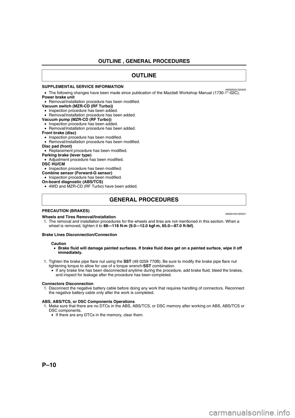
SUPPLEMENTAL SERVICE INFORMATIONA6E690201020205•The following changes have been made since publication of the Mazda6 Workshop Manual (1730-1*-02C).
Power brake unit
•Removal/installation procedure has been modified.
Vacuum switch (MZR-CD (RF Turbo))
•Inspection procedure has been added.
•Removal/installation procedure has been added.
Vacuum pump (MZR-CD (RF Turbo))
•Inspection procedure has been added.
•Removal/installation procedure has been added.
Front brake (disc)
•Inspection procedure has been modified.
•Removal/installation procedure has been modified.
Disc pad (front)
•Replacement procedure has been modified.
Parking brake (lever type)
•Adjustment procedure has been modified.
DSC HU/CM
•Inspection procedure has been modified.
Combine sensor (Forward-G sensor)
•Inspection procedure has been modified.
On-board diagnostic (ABS/TCS)
•4WD and MZR-CD (RF Turbo) have been added.
End Of Sie
PRECAUTION (BRAKES)A6E691001020201Wheels and Tires Removal/Installation
1. The removal and installation procedures for the wheels and tires are not mentioned in this section. When a
wheel is removed, tighten it to 88—118 N·m {9.0—12.0 kgf·m, 65.0—87.0 ft·lbf}.
Brake Lines Disconnection/Connection
Caution
•Brake fluid will damage painted surfaces. If brake fluid does get on a painted surface, wipe it off
immediately.
1. Tighten the brake pipe flare nut using the SST (49 0259 770B). Be sure to modify the brake pipe flare nut
tightening torque to allow for use of a torque wrench-SST combination.
•If any brake line has been disconnected anytime during the procedure, add brake fluid, bleed the brakes,
and inspect for leakage after the procedure has been completed.
Connectors Disconnection
1. Disconnect the negative battery cable before doing any work that requires handling of connectors. Reconnect
the negative battery cable only after the work is completed.
ABS, ABS/TCS, or DSC Components Operations
1. Make sure that there are no DTCs in the ABS, ABS/TCS, or DSC memory after working on ABS, ABS/TCS or
DSC components.
•If there are any DTCs in the memory, clear them.
End Of Sie
OUTLINE
GENERAL PROCEDURES
Page 765 of 909

OUTLINE
R–3
R
SPECIFICATIONSA6E740201013203
*1: Engine coolant and engine oil are at specified level. Fuel is full. Spare tire, jack and tools are in designated position.
*
2: Difference between left and right must not exceed 1 °30'.*3: Distance between wheel center and fender brim is following. 4SD and 5HB front: 402 mm {15.82 in} (reference
value) 4SD and 5HB rear: 401 mm {15.78 in} (reference value), WGN (2WD) front: 405 mm {15.94 in}
(reference value) WGN (2WD) rear: 407 mm {16.02 in} (reference value)
Bold frames: New specifications
End Of Sie
Item Specification
New Mazda6 Current
Mazda6
GG (4SD, 5HB) GY (WGN 2WD) GY (WGN 4WD) GG (4SD, 5HB)
Engine type LF, MZR-CD
(RF Turbo) L8, LF, L3,
MZR-CD (RF Turbo) L3 L8, LF, L3
Fr o nt
suspension Type High-mount double wishbone (with double-pivoted lower arm(s))
Spring type Coil spring
Shock absorber type
Cylindrical, double-acting
(Low-pressure gas charged with rebound spring)
Stabilizer Type Torsion bar
Diameter (mm {in}) 23 {0.91}
Wheel
alignment
(Unloaded)*
1
Total toe-in (mm {in}) Tire: 2
±4 {0.08 ±0.16}, Rim inner: 1 ±3 {0.04 ±0.12}
(degree) 0 °11 ′±0°22 ′
Maximum
steering
angle inner
18 inch wheel specification vehicles: 36
°±3°
Except for above: 39 °±3°
outer 18 inch wheel specification vehicles: 30
°±3°
Except for above: 31 °±3°
Caster
angle*
2
(reference
value) normal 3
°47 ′±1° 3°40 ′±1° 3°35 ′±1° 3°47 ′±1°
elevated*33 °42' ±1° 3°35 ′±1° —3 °42' ±1 °
Camber
angle*
2
(reference
value) normal –0
°17 ′±1° –0°15 ′±1° –0°08 ′±1° –0°17 ′±1°
elevated*3–0 °10' ±1° –0°08 ′±1° —–0 °10' ±1°
Steering
axis
inclination
(reference
value) normal 5
°28 ′ 5°24 ′ 5°16 ′ 5°28 ′
elevated
*35 °18' 5 °16 ′ —5 °18'
Rear
suspension Type E-type multi-link
Spring type Coil spring
Stabilizer
Type Torsion bar
Diameter (mm {in})
4SD: 19 {0.75}
5HB: 18 {0.71}18 {0.71} 21 {0.83}
4SD: 19 {0.75}
5HB: 18 {0.71}
Shock absorber type Cylindrical,
double-acting
(Low-pressure gas charged) Cylindrical,
double-acting
(Low-pressure gas charged)/
(High-pressure
gas charged) Cylindrical,
double-acting
(High-pressure gas charged) Cylindrical,
double-acting
(Low-pressure gas charged)
Wheel
alignment
(Unloaded)*
1
Total toe-in (mm {in}) Tire: 2
±4 {0.08 ±0.16}, Rim inner: 1 ±3 {0.04 ±0.12}
(degree) 0 °11 ′±0°22 ′
Camber
angle*
2
normal –1 °13 ′±1° –1°06 ′±1° –1°03 ′±1° –1°13 ′±1°
elevated
*3–1 °05 ′±1° –0°58 ′±1° —–1 °05 ′±1°
Thrust angle (degree) 0 °±0°48 ′
Page 816 of 909

MULTIPLEX COMMUNICATION SYSTEM
T–5
T
End Of Sie
Cruise main indicator light
conditions (MZR-CD (RF
Turbo))OUT–––IN
Cruise set indicator light
conditions (MZR-CD (RF
Turbo))OUT–––IN
Desired gear/
selector lever
positionFN4A-EL OUT–IN–IN
JA5AX-EL IN OUT IN IN IN
ECT OUT IN–IN
Engine control condition OUT–IN––
Engine displacement OUT–IN––
Engine loss torque (except
MZR-CD (RF Turbo))OUT IN–––
Engine speed OUT IN IN IN IN
Engine torque (except
MZR-CD (RF Turbo))OUT IN–––
Fuel injection information OUT–IN––
Fuel type and delivery OUT–IN––
Gear position IN OUT IN IN IN
Generator warning light
conditions (except MZR-
CD (RF Turbo))OUT–––IN
Glow indicator light
condition (MZR-CD (RF
Turbo))OUT–––IN
HOLD indicator light
conditions (FN4A-EL)OUT–––IN
Idle speed up request IN OUT–––
MIL condition (except
MZR-CD (RF Turbo))OUT–––IN
MIL indicate request IN OUT–––
Number of cylinders OUT–IN––
Racing select
determinationIN OUT–––
TCC condition IN OUT–––
Tire circumference (front/
rear)OUT–IN––
Torque reduction inhibit OUT IN IN––
TP OUTINININ–
Transmission/axle type OUT–IN––
Travelled distanceIN–OUT––
IN OUT––IN
OUT–––IN
Torque
reduction
requestJA5AX-EL IN OUT–––
except
JA5AX-ELIN–OUT––
Turbine speed IN OUT–––
Upper torque limit IN OUT–––
Vehicle speedOUT–––IN
IN OUT–––
Wheel speed (front left/
front right/rear left/rear
right)IN IN OUT IN–
OUT–––IN
4WD system operating
condition (warning light
information)–––OUT IN SignalMultiplex module
PCM TCMABS (ABS/TCS)
HU/CM or
DSC HU/CM4WD control
moduleInstrument
cluster
Page 900 of 909

TD–8
TECHNICAL DATA
Wheel and Tires
*
1: Total weight exceeds 160 g {5.65 oz}.
*2: One balance weight: 60 g {2.12 oz} max. If the total weight exceeds 100 g {3.53 oz} on one side, rebalance after moving the tire around on the rim. Do not use 3 or more balance weights.
End Of Sie
BODY ELECTRICAL SYSTEMA6E931001047201
End Of Sie
Item Specification
Standard tire and wheel
Wheel Size 15
× 6JJ 16 × 7JJ 17 × 7JJ 18 × 7J
Offset (mm {in}) 50 {1.97} 55 {2.17} 55 {2.17}
Pitch circle diameter (mm {in}) 114.3 {4.50} 114.3 {4.50}
Material Steel Aluminum alloy Aluminum alloy
Tire Size 195/65R15 91V 205/55R16 91V
215/45R17
87W 215/45R17
91W
(reinforced) 215/45R18 89W
Air pressure
(kPa {kgf/
cm
2, psi}) Front
Up to 4
persons
220 {2.2, 32} 2WD: 230
{2.3, 33}
4WD: 250 {2.5, 36} 220 {2.2, 32}
Full load 240 {2.4, 35} 2WD: 240
{2.4, 35}
4WD: 250 {2.5, 36} 240 {2.4, 35}
Rear Up to 4
persons
220 {2.2, 32} 2WD: 230
{2.3, 33}
4WD: 250 {2.5, 36} 220 {2.2, 32}
Full load 300 {3.1, 44} 270 {2.8, 39} 270 {2.8, 39}
Remaining tread (mm {in}) 1.6 {0.06} 1.6 {0.06}
Wheel
and
tire Wheel and tire
runout
Radial
direction
1.5 {0.06} max. 1.5 {0.06} max.
(mm {in}) Lateral direction 2.5 {0.10} max. 2.0 {0.08} max. 2.0 {0.08} max.
Wheel imbalance (g {oz}) Knock-type*
2:
9 {0.32} max. Adhesive-type*
1:
13 {0.46} max.
Knock-type*
2:
8 {0.28} max. Adhesive-type*
1:
11 {0.39} max.
Knock-type*
2:
7 {0.25} max. Adhesive-type*
1:
10 {0.35} max.
Knock-type*
2:
6 {0.21} max.
Temporary spare tire
Wheel Size 15
×4T
Offset (mm {in}) 40 {1.57}
Pitch circle diameter (mm {in}) 114.3 {4.50}
Material Steel
Tire Size T115/70 D15 T135/90 D15
Air pressure
(kPa {kgf/cm
2,
psi}) 420 {4.2, 60}
Wheel
and
tire Wheel and tire
runout
Radial
direction
2.0 {0.08} max.
(mm {in}) Lateral direction 2.5 {0.10} max.
Item Specifications
Exterior light bulb capacity (W) High-mount brake
lightWGNIn-vehicle-type 18.4
× 1
Rear spoiler
type 4
× 1 (LED)
Interior light bulb capacity (W) Cargo compartment light 10 × 1