turn signal MAZDA 6 2002 Workshop Manual Suplement
[x] Cancel search | Manufacturer: MAZDA, Model Year: 2002, Model line: 6, Model: MAZDA 6 2002Pages: 909, PDF Size: 17.16 MB
Page 121 of 909
CONTROL SYSTEM
F1–33
F1
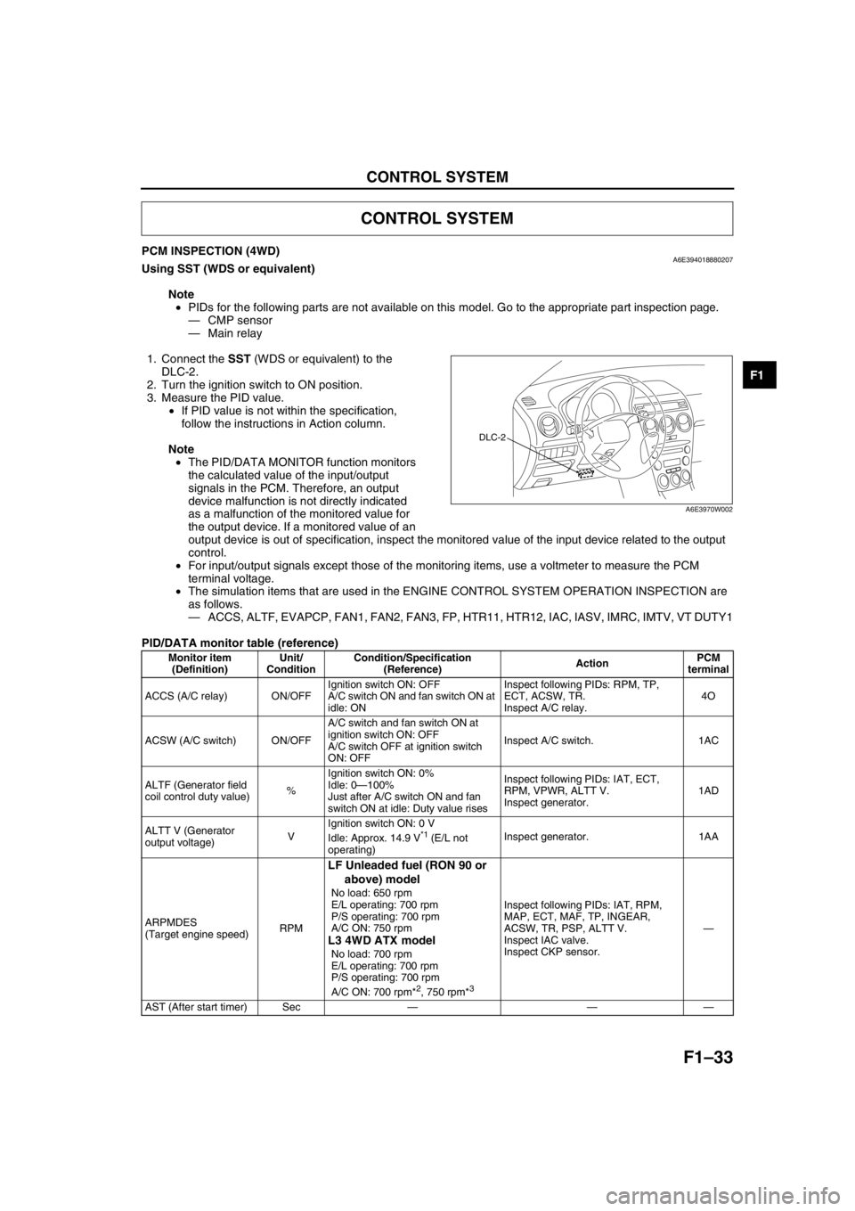
PCM INSPECTION (4WD)A6E394018880207Using SST (WDS or equivalent)
Note
•PIDs for the following parts are not available on this model. Go to the appropriate part inspection page.
—CMP sensor
—Main relay
1. Connect the SST (WDS or equivalent) to the
DLC-2.
2. Turn the ignition switch to ON position.
3. Measure the PID value.
•If PID value is not within the specification,
follow the instructions in Action column.
Note
•The PID/DATA MONITOR function monitors
the calculated value of the input/output
signals in the PCM. Therefore, an output
device malfunction is not directly indicated
as a malfunction of the monitored value for
the output device. If a monitored value of an
output device is out of specification, inspect the monitored value of the input device related to the output
control.
•For input/output signals except those of the monitoring items, use a voltmeter to measure the PCM
terminal voltage.
•The simulation items that are used in the ENGINE CONTROL SYSTEM OPERATION INSPECTION are
as follows.
—ACCS, ALTF, EVAPCP, FAN1, FAN2, FAN3, FP, HTR11, HTR12, IAC, IASV, IMRC, IMTV, VT DUTY1
PID/DATA monitor table (reference)
CONTROL SYSTEM
DLC-2
A6E3970W002
Monitor item
(Definition)Unit/
ConditionCondition/Specification
(Reference)ActionPCM
terminal
ACCS (A/C relay) ON/OFFIgnition switch ON: OFF
A/C switch ON and fan switch ON at
idle: ONInspect following PIDs: RPM, TP,
ECT, ACSW, TR.
Inspect A/C relay.4O
ACSW (A/C switch) ON/OFFA/C switch and fan switch ON at
ignition switch ON: OFF
A/C switch OFF at ignition switch
ON: OFFInspect A/C switch. 1AC
ALTF (Generator field
coil control duty value)%Ignition switch ON: 0%
Idle: 0—100%
Just after A/C switch ON and fan
switch ON at idle: Duty value risesInspect following PIDs: IAT, ECT,
RPM, VPWR, ALTT V.
Inspect generator.1AD
ALTT V (Generator
output voltage)VIgnition switch ON: 0 V
Idle: Approx. 14.9 V
*1 (E/L not
operating)Inspect generator. 1AA
ARPMDES
(Target engine speed)RPM
LF Unleaded fuel (RON 90 or
above) model
No load: 650 rpm
E/L operating: 700 rpm
P/S operating: 700 rpm
A/C ON: 750 rpm
L3 4WD ATX model
No load: 700 rpm
E/L operating: 700 rpm
P/S operating: 700 rpm
A/C ON: 700 rpm*
2, 750 rpm*3
Inspect following PIDs: IAT, RPM,
MAP, ECT, MAF, TP, INGEAR,
ACSW, TR, PSP, ALTT V.
Inspect IAC valve.
Inspect CKP sensor.—
AST (After start timer) Sec———
Page 126 of 909

F1–38
CONTROL SYSTEM
1QRefrigerant
pressure switch
(middle)Refrigerant
pressure switch
(middle)A/C ONRefrigerant
pressure is
above 1.52
MPaBelow 1.0
•Inspect refrigerant
pressure switch
•Inspect related
harness Refrigerant
pressure is
below 1.23
MPaB+
1RClutch operation*
2Clutch switchClutch pedal depressed Below 1.0•Inspect clutch switch
•Inspect related
harness Clutch pedal released B+
—*
3————
1S—— — ——
1T—— — ——
1U—— — ——
1V—— — ——
1WNeutral position*
2Neutral switchShift lever is at neutral position Below 1.0
•Inspect neutral switch
•Inspect related
harness Shift lever is not at neutral
positionB+
Selector lever
position*
11TR switch
(terminal C)Ignition switch
ONP rangeApprox.
4.6
•Inspect TR switch
•Inspect related
harness R rangeApprox.
3.9
N rangeApprox.
3.2
D range*4
M range*5Approx.
2.5
S range*
4Approx.
1.7
L range*
4Approx.
0.94
—*
12————
1X—— — ——
1Y HO2S (rear) HO2S (rear)Ignition switch ON Approx. 0•Inspect HO2S (rear)
•Inspect related
harness Idle (after warm up) 0—1.0
1Z PSP PSP switch IdleSteering wheel
at straight
ahead positionB+•Inspect PSP switch
•Inspect power
steering system
•Inspect related
harness While turning
steering wheelBelow 1.0
1AAGenerator output
voltageGenerator
(terminal P)•Inspect using the wave profile.
(See F1–44 Inspection Using An
Oscilloscope (Reference).)•Inspect generator
•Inspect related
harness
1AB HO2S (front) HO2S (front)•Inspect using the wave profile.
(See F1–44 Inspection Using An
Oscilloscope (Reference).)•Inspect HO2S (front)
•Inspect related
harness
1AC A/C on signalRefrigerant
pressure switchIdleA/C switch and
fan switch onBelow 1.0•Inspect refrigerant
pressure switch
•Inspect related
harness A/C switch off B+
1ADGenerator field coil
controlGenerator
(terminal D)•Inspect using the wave profile.
(See F1–44 Inspection Using An
Oscilloscope (Reference).)•Inspect generator
•Inspect related
harness
2A Throttle position TP sensorIgnition switch
ONCTP0.65—
1.15•Inspect TP sensor
•Inspect related
harness
WOT 4.3—4.8
2B—— — ——
2C—— — —— Terminal Signal Connected to Test conditionVoltage
(V)Action
Page 149 of 909
TROUBLESHOOTING
F1–61
F1
End Of Sie
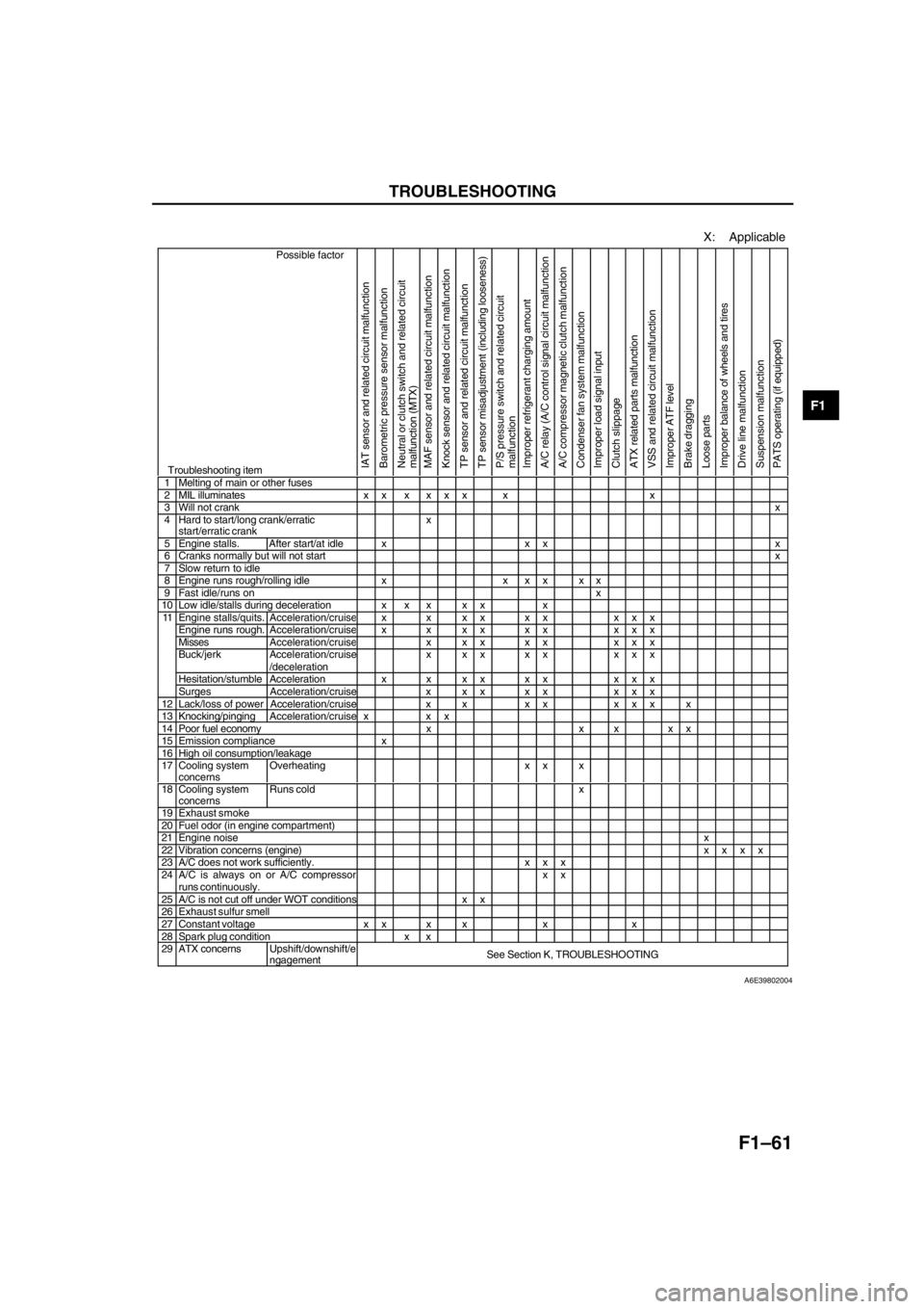
X: Applicable
Possible factor
Troubleshooting itemIAT sensor and related circuit malfunction
Barometric pressure sensor malfunction
Neutral or clutch switch and related circuit
malfunction (MTX)
MAF sensor and related circuit malfunction
Knock sensor and related circuit malfunction
TP sensor and related circuit malfunction
TP sensor misadjustment (including looseness)
P/S pressure switch and related circuit
malfunction
Improper refrigerant charging amount
A/C relay (A/C control signal circuit malfunction
A/C compressor magnetic clutch malfunction
Condenser fan system malfunction
Improper load signal input
Clutch slippage
ATX related parts malfunction
VSS and related circuit malfunction
Improper ATF level
Brake dragging
Loose parts
Improper balance of wheels and tires
Drive line malfunction
Suspension malfunction
PATS operating (if equipped)
1 Melting of main or other fuses2 MIL illuminates x x x x x x x x3 Will not crankx4 Hard to start/long crank/erratic
start/erratic crankx
5 Engine stalls. After start/at idle x x x x6 Cranks normally but will not startx7 Slow return to idle8 Engine runs rough/rolling idle x x x x x x9 Fast idle/runs onx10 Low idle/stalls during deceleration x x x x x xEngine stalls/quits.Acceleration/cruisex x xx xx xxxEngine runs rough. Acceleration/cruisex x xx xx xxxMissesAcceleration/cruisex xx xx xxxBuck/jerk Acceleration/cruise
/decelerationx xx xx xxx
Hesitation/stumble Acceleration x x x x x x x x x
11
Surges Acceleration/cruise x x x x x x x x
12 Lack/loss of power Acceleration/cruise x x x x x x x x13 Knocking/pingingAcceleration/cruise x x x14 Poor fuel economy x x x x x15 Emission compliance x16 High oil consumption/leakage17 Cooling system
concernsOverheating x x x
18 Cooling system
concernsRuns cold x
19 Exhaust smoke20 Fuel odor (in engine compartment)21 Engine noisex22 Vibration concerns (engine)xxxx23 A/C does not work sufficiently. x x x24 A/C is always on or A/C compressorruns continuously.xx25 A/C is not cut off under WOT conditions x x26 Exhaust sulfur smell27 Constant voltage x x x x x x28 Spark plug condition x x29 ATX concernsUpshift/downshift/e
ngagementSee Section K, TROUBLESHOOTING
A6E39802004
Page 217 of 909
CONTROL SYSTEM
F2–65
F2
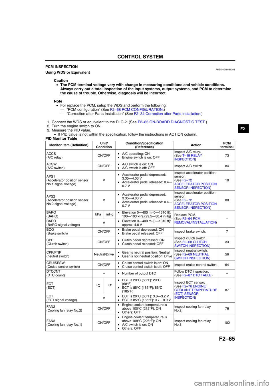
End Of SiePCM INSPECTIONA6E404018881208Using WDS or Equivalent
Caution
•The PCM terminal voltage vary with change in measuring conditions and vehicle conditions.
Always carry out a total inspection of the input systems, output systems, and PCM to determine
the cause of trouble. Otherwise, diagnosis will be incorrect.
Note
•For replace the PCM, setup the WDS and perform the following.
—“PCM configuration” (See F2–68 PCM CONFIGURATION.)
—“Correction after Parts Installation” (See F2–34 Correction after Parts Installation.)
1. Connect the WDS or equivalent to the DLC-2. (See F2–85 ON-BOARD DIAGNOSTIC TEST.)
2. Turn the engine switch to ON.
3. Measure the PID value.
•If PID value is not within the specification, follow the instructions in ACTION column.
PID Monitor Table
Monitor item (Definition)Unit/
ConditionCondition/Specification
(Reference)ActionPCM
terminal
ACCS
(A/C relay)ON/OFF•A/C operating: ON
•Engine switch is on: OFFInspect A/C relay.
(See T–19 RELAY
INSPECTION)73
ACSW
(A/C switch)ON/OFF•A/C switch is on: ON
•A/C switch is off: OFFInspect A/C switch. 84
APS1
(Accelerator position sensor
No.1 signal voltage)V•Accelerator pedal depressed:
3.35—4.03 V
•Accelerator pedal released: 0.4—
0.7 VInspect accelerator position
sensor.
(See F2–72
ACCELERATOR POSITION
SENSOR INSPECTION)10
APS2
(Accelerator position sensor
No.2 signal voltage)V•Accelerator pedal depressed:
3.35—4.03 V
•Accelerator pedal released: 0.4—
0.7 VInspect accelerator position
sensor.
(See F2–72
ACCELERATOR POSITION
SENSOR INSPECTION)88
BARO
(BARO)kPa inHg•Elevation 0—400 m {0—1310 ft}:
100—103 kPa {29.5—30.4 inHg}Replace PCM.
(See F2–64 PCM
REMOVAL/INSTALLATION)–
BARO
(BARO signal voltage)V•Elevation 0—400 m {0—1310 ft}:
approx. 4.0 V
BOO
(Brake switch)ON/OFF•Brake pedal depressed: ON
•Brake pedal released: OFFInspect brake switch. 7
CPP
(Clutch switch)ON/OFF•Clutch pedal depressed: ON
•Clutch pedal released: OFFInspect clutch switch.
(See F2–68 CLUTCH
SWITCH INSPECTION)33
CPP/PNP
(neutral switch)Neutral/Drive•Gear is neutral position: Neutral
•Gear is not neutral position: DriveInspect neutral switch.
(See F2–69 NEUTRAL
SWITCH INSPECTION)56
CRUISESW
(Cruise control switch)ON/OFF•Cruise control switch is on: ON
•Cruise control switch is off: OFFInspect cruise control switch. 64
DTCCNT
(DTC count)–•Number of output DTCFollow DTC inspection.
(See F2–87 DTC TABLE)–
ECT
(ECT)°C°F•ECT is 20°C {68°F}: 20°C
{68°F}
•ECT is 85°C {185°F}: 85°C
{185°F}Inspect ECT sensor.
(See F2–76 ENGINE
COOLANT TEMPERATURE
(ECT) SENSOR
INSPECTION)87
ECT
(ECT signal voltage)V•ECT is 20°C {68°F}: 3.0—3.2 V
•ECT is 85°C {185°F}: 0.7—0.9 V
FAN2
(Cooling fan relay No.2)ON/OFF•Engine coolant temperature is
above 100°C {212°F}: ON
•Others: OFFInspect cooling fan relay
No.2.76
FAN3
(Cooling fan relay No.1)ON/OFF•Engine coolant temperature is
above 108°C {226°F}: ON
•A/C switch is on: ON
•Others: OFFInspect cooling fan relay
No.1.102
Page 223 of 909
CONTROL SYSTEM
F2–71
F2
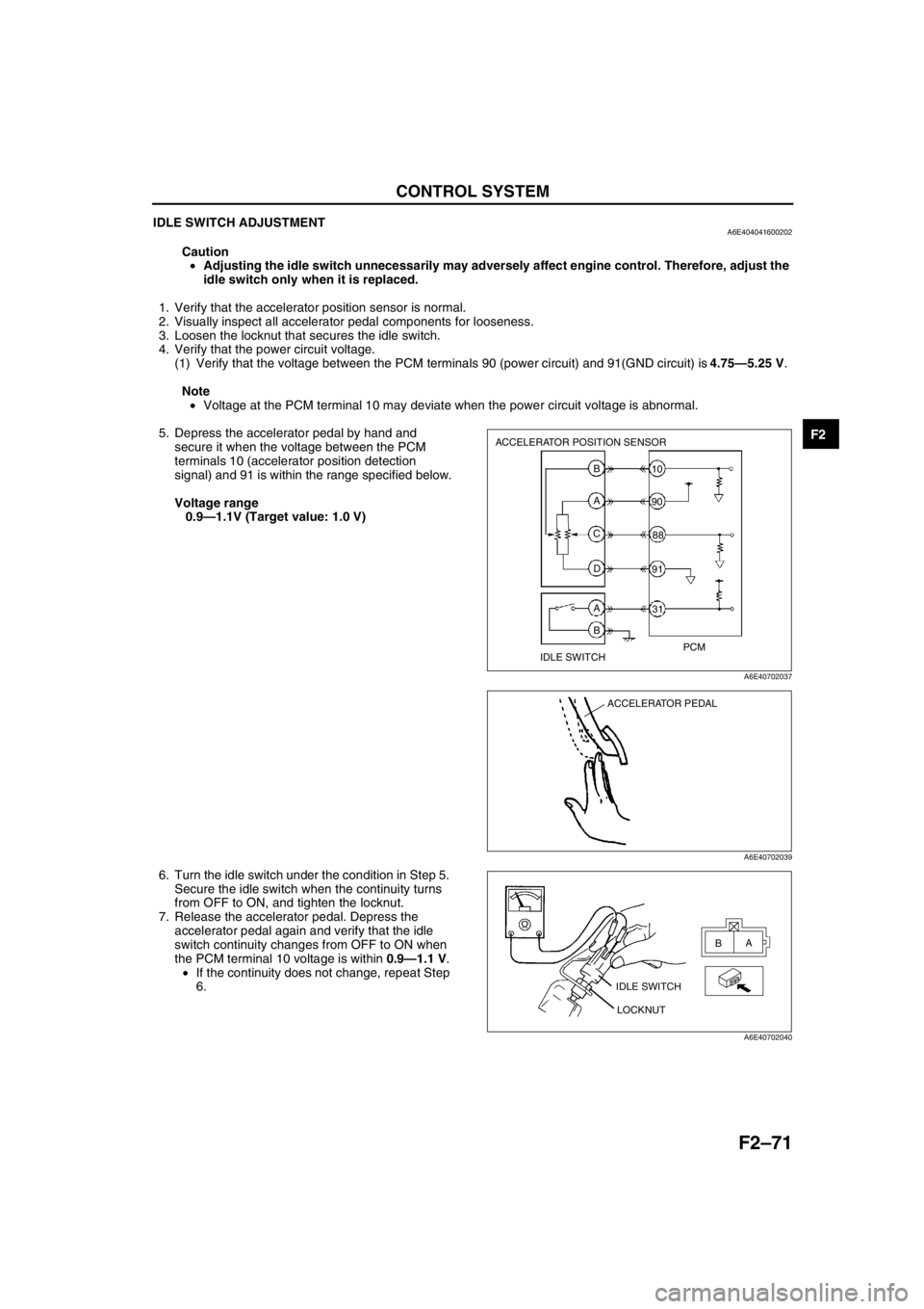
IDLE SWITCH ADJUSTMENTA6E404041600202
Caution
•Adjusting the idle switch unnecessarily may adversely affect engine control. Therefore, adjust the
idle switch only when it is replaced.
1. Verify that the accelerator position sensor is normal.
2. Visually inspect all accelerator pedal components for looseness.
3. Loosen the locknut that secures the idle switch.
4. Verify that the power circuit voltage.
(1) Verify that the voltage between the PCM terminals 90 (power circuit) and 91(GND circuit) is 4.75—5.25 V.
Note
•Voltage at the PCM terminal 10 may deviate when the power circuit voltage is abnormal.
5. Depress the accelerator pedal by hand and
secure it when the voltage between the PCM
terminals 10 (accelerator position detection
signal) and 91 is within the range specified below.
Voltage range
0.9—1.1V (Target value: 1.0 V)
6. Turn the idle switch under the condition in Step 5.
Secure the idle switch when the continuity turns
from OFF to ON, and tighten the locknut.
7. Release the accelerator pedal. Depress the
accelerator pedal again and verify that the idle
switch continuity changes from OFF to ON when
the PCM terminal 10 voltage is within 0.9—1.1 V.
•If the continuity does not change, repeat Step
6.
End Of Sie
ACCELERATOR POSITION SENSOR
IDLE SWITCHPCM B
A
C
D
A
B31 10
90
88
91
A6E40702037
ACCELERATOR PEDAL
A6E40702039
IDLE SWITCH
LOCKNUTA
B
A6E40702040
Page 226 of 909
F2–74
CONTROL SYSTEM
MASS AIR FLOW (MAF)/INTAKE AIR TEMPERATURE (IAT) SENSOR INSPECTIONA6E404013210201
Note
•Perform the following test only when directed.
•Perform “MAF Correction” after replacing the MAF/IAT sensor. (See F2–35 MAF Correction.)
MAF Sensor Voltage Inspection
1. Turn the engine switch to ON.
2. Monitor the MAF PID using the WDS or equivalent.
•If not as specified, perform the “Circuit Open/Short Inspection”.
MAF PID
0.0—1.0 V
3. Start the engine and warm up the engine completely.
4. Monitor the MAF PID using the WDS or equivalent at idle.
•If not as specified, perform the “Circuit Open/Short Inspection”.
MAF PID
1.5—2.1 V
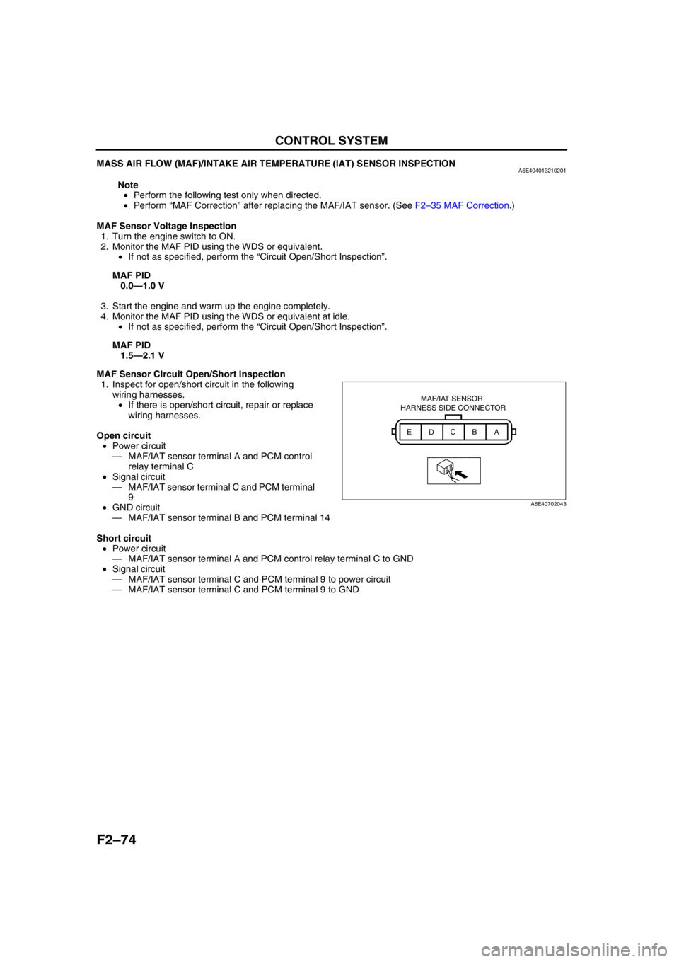
MAF Sensor CIrcuit Open/Short Inspection
1. Inspect for open/short circuit in the following
wiring harnesses.
•If there is open/short circuit, repair or replace
wiring harnesses.
Open circuit
•Power circuit
—MAF/IAT sensor terminal A and PCM control
relay terminal C
•Signal circuit
—MAF/IAT sensor terminal C and PCM terminal
9
•GND circuit
—MAF/IAT sensor terminal B and PCM terminal 14
Short circuit
•Power circuit
—MAF/IAT sensor terminal A and PCM control relay terminal C to GND
•Signal circuit
—MAF/IAT sensor terminal C and PCM terminal 9 to power circuit
—MAF/IAT sensor terminal C and PCM terminal 9 to GND
MAF/IAT SENSOR
HARNESS SIDE CONNECTOR
A
B
C
D E
A6E40702043
Page 228 of 909
F2–76
CONTROL SYSTEM
ENGINE COOLANT TEMPERATURE (ECT) SENSOR REMOVAL/INSTALLATIONA6E404018840201
Warning•When the engine is hot, it can badly burn. Turn off the engine and wait until it is cool before
removing the ECT sensor.
1. Disconnect the negative battery cable.
2. Drain the engine coolant. (See Section E ENGINE COOLANT REPLACEMENT.)
3. Remove the common rail. (See F2–53 SUPPLY PUMP REMOVAL/INSTALLATION .)
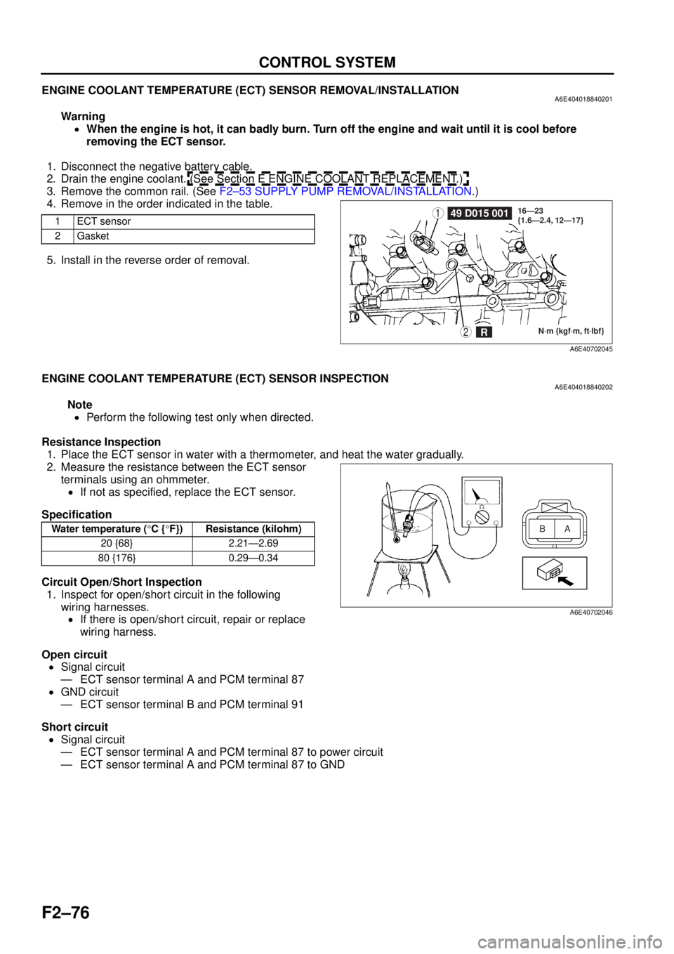
4. Remove in the order indicated in the table.
5. Install in the reverse order of removal.
End Of Sie
ENGINE COOLANT TEMPERATURE (ECT) SENSOR INSPECTIONA6E404018840202
Note
• Perform the following test only when directed.
Resistance Inspection 1. Place the ECT sensor in water with a thermometer, and heat the water gradually.
2. Measure the resistance between the ECT sensor terminals using an ohmmeter.
• If not as specified, replace the ECT sensor.
Specification
Circuit Open/Short Inspection 1. Inspect for open/short circuit in the following
wiring harnesses.• If there is open/short circuit, repair or replace
wiring harness.
Open circuit • Signal circuit
— ECT sensor terminal A and PCM terminal 87
• GND circuit
— ECT sensor terminal B and PCM terminal 91
Short circuit • Signal circuit
— ECT sensor terminal A and PCM terminal 87 to power circuit
— ECT sensor terminal A and PCM terminal 87 to GND
End Of Sie
1ECT sensor
2Gasket149 D015 001
N·m {kgf·m, ft·lbf}
16—23
{1.6—2.4, 12—17}2R
A6E40702045
Water temperature (
°C { °F}) Resistance (kilohm)
20 {68} 2.21—2.69
80 {176} 0.29—0.34A
B
A6E40702046
Page 230 of 909
F2–78
CONTROL SYSTEM
BOOST SENSOR INSPECTIONA6E404013214201
Note
•Perform the following test only when directed.
Visual Inspection
1. Inspect the boost sensor for damage and cracks.
•If not as specified, replace the boost sensor.
2. Inspect vacuum hose for improper routing, kinks or leakage.
•If there is any malfunction, repair or replace suspected hose.
Voltage Inspection
1. Turn the engine switch to ON.
2. Monitor the MAP PID using the WDS or equivalent.
•If not as specified, perform the “Circuit Open/Short Inspection”.
MAP PID
2.1—2.5 V
3. Start the engine and warm up the engine completely.
4. Monitor the MAP PID using the WDS or equivalent at idle.
•If not as specified, perform the “Circuit Open/Short Inspection”.
MAP PID
2.1—2.5 V
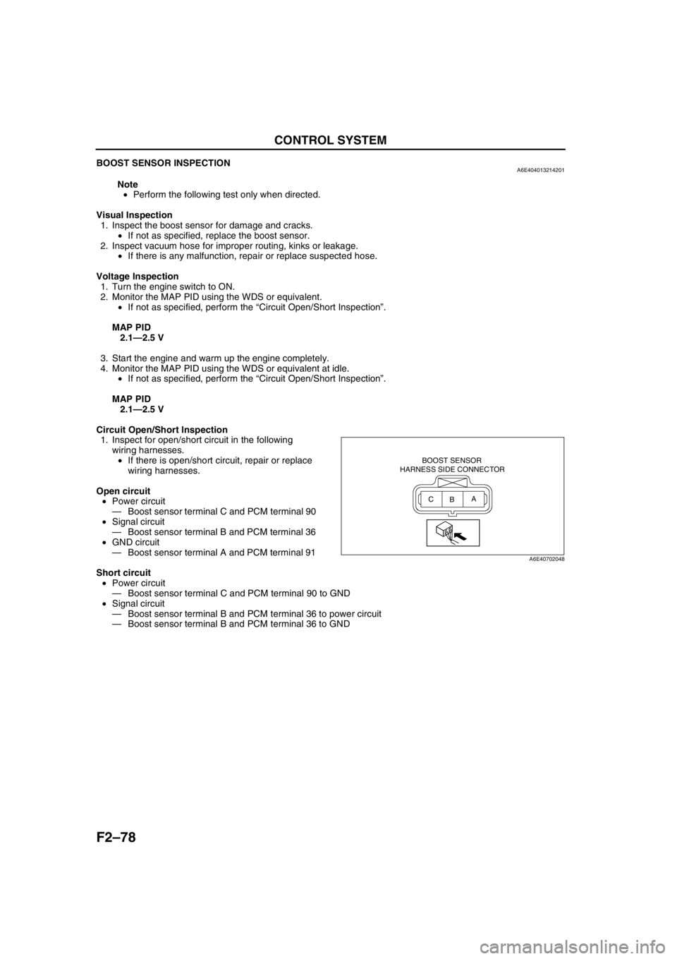
Circuit Open/Short Inspection
1. Inspect for open/short circuit in the following
wiring harnesses.
•If there is open/short circuit, repair or replace
wiring harnesses.
Open circuit
•Power circuit
—Boost sensor terminal C and PCM terminal 90
•Signal circuit
—Boost sensor terminal B and PCM terminal 36
•GND circuit
—Boost sensor terminal A and PCM terminal 91
Short circuit
•Power circuit
—Boost sensor terminal C and PCM terminal 90 to GND
•Signal circuit
—Boost sensor terminal B and PCM terminal 36 to power circuit
—Boost sensor terminal B and PCM terminal 36 to GND
End Of Sie
BOOST SENSOR
HARNESS SIDE CONNECTOR
A
B C
A6E40702048
Page 231 of 909
CONTROL SYSTEM
F2–79
F2
FUEL PRESSURE SENSOR INSPECTIONA6E404013015201
Note
•Perform the following test only when directed.
Voltage Inspection
1. Start the engine and warm up the engine completely.
2. Measure the voltage between fuel pressure sensor terminals A and B using a voltmeter at idle.
•If not as specified, perform the “Circuit Open/Short Inspection”.
—If there is no open/short circuit, replace the common rail.
Specification
1.4—1.7 V
3. Turn off the engine and wait three minutes.
4. Turn the engine switch to ON.
5. Measure the voltage between fuel pressure
sensor terminals A and B using a voltmeter.
•If not as specified, perform the “Circuit Open/
Short Inspection”.
—If there is no open/short circuit, replace
the common rail.
Specification
0.9—1.1 V
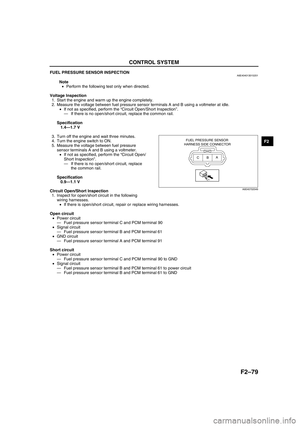
CIrcuit Open/Short Inspection
1. Inspect for open/short circuit in the following
wiring harnesses.
•If there is open/short circuit, repair or replace wiring harnesses.
Open circuit
•Power circuit
—Fuel pressure sensor terminal C and PCM terminal 90
•Signal circuit
—Fuel pressure sensor terminal B and PCM terminal 61
•GND circuit
—Fuel pressure sensor terminal A and PCM terminal 91
Short circuit
•Power circuit
—Fuel pressure sensor terminal C and PCM terminal 90 to GND
•Signal circuit
—Fuel pressure sensor terminal B and PCM terminal 61 to power circuit
—Fuel pressure sensor terminal B and PCM terminal 61 to GND
End Of Sie
FUEL PRESSURE SENSOR
HARNESS SIDE CONNECTOR
A
B C
A6E40702049
Page 240 of 909
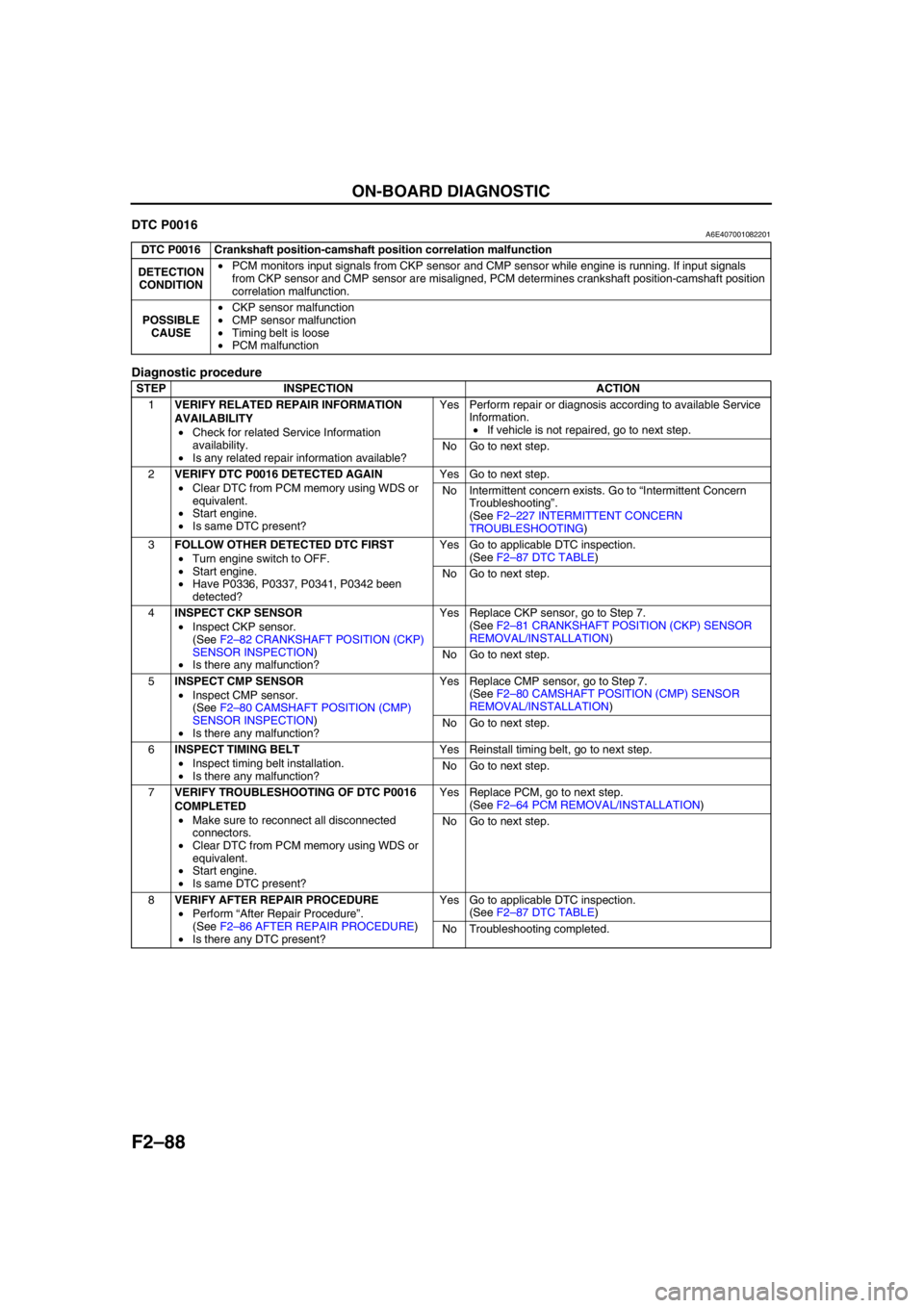
F2–88
ON-BOARD DIAGNOSTIC
End Of SieDTC P0016A6E407001082201
Diagnostic procedure
End Of Sie
DTC P0016 Crankshaft position-camshaft position correlation malfunction
DETECTION
CONDITION•PCM monitors input signals from CKP sensor and CMP sensor while engine is running. If input signals
from CKP sensor and CMP sensor are misaligned, PCM determines crankshaft position-camshaft position
correlation malfunction.
POSSIBLE
CAUSE•CKP sensor malfunction
•CMP sensor malfunction
•Timing belt is loose
•PCM malfunction
STEP INSPECTION ACTION
1VERIFY RELATED REPAIR INFORMATION
AVAILABILITY
•Check for related Service Information
availability.
•Is any related repair information available?Yes Perform repair or diagnosis according to available Service
Information.
•If vehicle is not repaired, go to next step.
No Go to next step.
2VERIFY DTC P0016 DETECTED AGAIN
•Clear DTC from PCM memory using WDS or
equivalent.
•Start engine.
•Is same DTC present?Yes Go to next step.
No Intermittent concern exists. Go to “Intermittent Concern
Troubleshooting”.
(See F2–227 INTERMITTENT CONCERN
TROUBLESHOOTING)
3FOLLOW OTHER DETECTED DTC FIRST
•Turn engine switch to OFF.
•Start engine.
•Have P0336, P0337, P0341, P0342 been
detected?Yes Go to applicable DTC inspection.
(See F2–87 DTC TABLE)
No Go to next step.
4INSPECT CKP SENSOR
•Inspect CKP sensor.
(See F2–82 CRANKSHAFT POSITION (CKP)
SENSOR INSPECTION)
•Is there any malfunction?Yes Replace CKP sensor, go to Step 7.
(See F2–81 CRANKSHAFT POSITION (CKP) SENSOR
REMOVAL/INSTALLATION)
No Go to next step.
5INSPECT CMP SENSOR
•Inspect CMP sensor.
(See F2–80 CAMSHAFT POSITION (CMP)
SENSOR INSPECTION)
•Is there any malfunction?Yes Replace CMP sensor, go to Step 7.
(See F2–80 CAMSHAFT POSITION (CMP) SENSOR
REMOVAL/INSTALLATION)
No Go to next step.
6INSPECT TIMING BELT
•Inspect timing belt installation.
•Is there any malfunction?Yes Reinstall timing belt, go to next step.
No Go to next step.
7VERIFY TROUBLESHOOTING OF DTC P0016
COMPLETED
•Make sure to reconnect all disconnected
connectors.
•Clear DTC from PCM memory using WDS or
equivalent.
•Start engine.
•Is same DTC present?Yes Replace PCM, go to next step.
(See F2–64 PCM REMOVAL/INSTALLATION)
No Go to next step.
8VERIFY AFTER REPAIR PROCEDURE
•Perform “After Repair Procedure”.
(See F2–86 AFTER REPAIR PROCEDURE)
•Is there any DTC present?Yes Go to applicable DTC inspection.
(See F2–87 DTC TABLE)
No Troubleshooting completed.