tow MAZDA 6 2002 Workshop Manual Suplement
[x] Cancel search | Manufacturer: MAZDA, Model Year: 2002, Model line: 6, Model: MAZDA 6 2002Pages: 909, PDF Size: 17.16 MB
Page 7 of 909

GI–4
FUNDAMENTAL PROCEDURES
DYNAMOMETERA6E2014000042174WD testing/servicing
•Brake tester
Caution
•
To ensure the stability of the drag force of the viscous coupling always perform a brake test after
using the dynamometer or speed meter tester.
Note
•If there is a great amount of brake drag, it is probably due to the viscosity of the viscous coupling or the
center differential (RBC). To remove the influence of the coupling, jack up all four wheels of the vehicle
and verify that each wheel can be rotated freely by hand.
•Chassis dynamometer/speed meter tester
Caution
•
The vehicle may sway or surge forward when on the dynamometer. To prevent possible vehicle
movement, firmly secure it in place using steel retainers (chain, wire or similar) attached to the
front and rear towing hooks or to the tie down hooks.
•
Do not pop the clutch.
•
Do not accelerate suddenly.
Note
•The dynamometer/speed meter tester has two setting modes: propeller shaft removed mode and free
roller mode. After placing the vehicle on the tester and setting the wheels on the free rollers, start the
engine. For MTX vehicles, set the shift lever into second gear and gently, at low idle speed, release the
clutch pedal. For ATX vehicles, set the selector lever to D range, and slowly accelerate.
End Of Sie
FUNDAMENTAL PROCEDURES
Page 11 of 909

GI–8
SCHEDULED MAINTENANCE
SCHEDULED MAINTENANCE TABLEA6E203400013202For Europe (L.H.D. U.K.)
Chart symbols:
I : Inspect and clean, repair, adjust, or replace if necessary.
R:Replace
C : Clean
Remarks:
SCHEDULED MAINTENANCE
•To ensure efficient operation of the engine and all systems related to emission control, the ignition and fuel systems must
be serviced regularly. It is strongly recommended that all servicing related to these systems be done by an authorized
Mazda Dealer.
•After the described period, continue to follow the described maintenance at the recommended intervals.
•Refer below for a description of items marked* in the maintenance chart.
*1: If the vehicle is operated under any of the following conditions, change the engine oil and oil filter every 10,000 km
(6,250 miles) or shorter.
a. Driving in dusty conditions.
b. Extended periods of idling or low speed operation.
c. Driving for long period in cold temperatures or driving regularly at short distance only.
*2: Also inspect and adjust the power steering and air conditioner drive belts, if installed.
*3: If the brakes are used extensively (for example, continuous hard driving or mountain driving) or if the vehicle is
operated in extremely humid climates, change the brake fluid annually.
*4: If the vehicle is operated in very dusty or sandy areas, clean and if necessary, replace the air cleaner element more
often than the recommended intervals.
*5: Replacement of the timing belt is required at every 100,000 km (62,500 miles).
Failure to replace the timing belt may result in damage to the engine.
*6: Replacement of the timing belt is required at every 120,000 km (75,000 miles).
Failure to replace the timing belt may result in damage to the engine.
*7: If the vehicle is operated under any of the following conditions, change the rear differential oil
every 40,000 km (25,000 miles).
a. Towing a trailer or using a car - top carrier
b. Driving in dusty, sandy or wet condition
c. Extended periods of idling or low speed operation
d. Repeated short trips of less than 16 km (10 miles)
*8: If this component has been submerged in water, the oil should be changed.
Maintenance ItemMaintenance Interval (Number of months or km (miles), whichever comes first)
Months 12 24 36 48 60 72 84 96 108
×1000 km 20 40 60 80 100 120 140 160 180
×1000 miles 12.52537.55062.57587.5100112.5
GASOLINE ENGINE
Spark plugs Replace every 100,000 km (62,500 miles)
Air cleaner element *4 R R R
E.G.R. system I I
DIESEL ENGINE
Engine valve clearance I I
Engine timing beltFinland, Sweden, Norway*5 Replace every 100,000 km (62,500 miles)
Others*6 Replace every 120,000 km (75,000 miles)
Fuel filter R R R
Fuel injection system I I I I
Air cleaner element *4CCRCCRCCR
E.G.R. system I I I
GASOLINE and DIESEL ENGINE
Engine oil *1RRRRRRRRR
Engine oil filter *1RRRRRRRRR
Drive belts *2 I I I
Cooling system (including coolant level adjustment) I I I I
Page 14 of 909

SCHEDULED MAINTENANCE
GI–11
GI
For GCC
Chart symbols:
I : Inspect and clean, repair, adjust, or replace if necessary.
R : Replace
T:Tighten
C : Clean
Remarks:
End Of Sie
Steering operation & linkages IIIII I
Manual transaxle oil R R
Automatic transaxle fluid level IIIII I
Front & rear suspension & ball joints IIIII
Driveshaft dust boots IIIII
Exhaust system & heat shields IIIII I
Bolts & nuts on seats IIIII I
Body condition (for rust, corrosion & perforation) Inspect annually
Cabin air filter (if installed) R R R R R R R R R R R RMaintenance ItemMaintenance Interval (Number of months or km (miles), whichever comes first)
Months 12 24 36 48 60 72 84 96 108 120 132 144
×1000 km 15 30 45 60 75 90 105 120 135 150 165 180
×1000 miles 9 18 27 36 45 54 63 72 81 90 99 108
•To ensure efficient operation of the engine and all systems related to emission control, the ignition and fuel systems must
be serviced regularly. It is strongly recommended that all servicing related to these systems be done by an authorized
Mazda Dealer.
•After the described period, continue to follow the described maintenance at the recommended intervals.
•Refer below for a description of items marked* in the maintenance chart.
*1: If the vehicle is operated under any of the following conditions, change the engine oil and oil filter more often than
recommended intervals.
a. Driving in dusty conditions.
b. Extended periods of idling or low speed operation.
c. Driving for long period in cold temperatures or driving regularly at short distance only.
*2: Also inspect and adjust the power steering and air conditioner drive belts, if installed.
*3: If the brakes are used extensively (for example, continuous hard driving or mountain driving) or if the vehicle is
operated in extremely humid climates, change the brake fluid annually.
*4: If the vehicle is operated in very dusty or sandy areas, clean and if necessary, replace the air cleaner element more
often than the recommended intervals.
*5: This is a full function check of electrical systems such as lights, wiper and washer systems (including wiper blades),
and power windows.
*6: If the vehicle is operated under any of the following conditions, change the rear differential oil
every 45,000 km (27,000 miles).
a. Towing a trailer or using a car - top carrier
b. Driving in dusty, sandy or wet condition
c. Extended periods of idling or low speed operation
d. Repeated short trips of less than 16 km (10 miles)
*7: If this component has been submerged in water, the oil should be changed.
Maintenance ItemMaintenance Interval (Number of months or km (miles), whichever comes first)
Months 6 121824303642485460667278849096
×1000 km
10 20 30 40 50 60 70 80 90 100 110 120 130 140 150 160
×1000 miles6.25 12.5 18.75 25 31.25 37.5 43.75 50 56.25 62.5 68.75 75 81.25 87.5 93.75 100
ENGINE
Engine valve clearance (leaded fuel) I I I I
Drive belts *2IIIIIIIIIIIIIIII
Engine oil *1RRRRRRRRRRRRRRRR
Engine oil filter *1RRRRRRRRRRRRRRRR
COOLING SYSTEM
Cooling system IIIIIIII
Engine coolant Replace every 2 years
Page 16 of 909

GI–12
SCHEDULED MAINTENANCE
GIGENE RAL INFORMATION
For Europe (L.H.D. U.K.)
Applied VIN (assumed):
JMZ GG12820# 202316-, JMZ GG12F20# 202316-, JMZ GG12F50# 202316-, JMZ GG14320# 202316-
JMZ GG14820# 202316-, JMZ GG14F20# 202316-, JMZ GG14F50# 202316-, JMZ GG12350# 202316-
JMZ GG14350# 202316-, JMZ GG1232✻
✻✻ ✻
# 202316-, JMZ GG1282✻
✻✻ ✻
# 202316-, JMZ GG12F2✻
✻✻ ✻
# 202316-
JMZ GG12F5✻
✻✻ ✻
# 202316-, JMZ GG1432✻
✻✻ ✻
# 202316-, JMZ GG1482✻
✻✻ ✻
# 202316-, JMZ GG14F2✻
✻✻ ✻
# 202316-
JMZ GG14F5✻
✻✻ ✻
# 202316-, JMZ GY19320# 146118-, JMZ GY19820# 146118-, JMZ GY19F20# 146118-
JMZ GY19F50# 146118-, JMZ GY89370# 146118-, JMZ GY19350# 146118-, JMZ GY1932✻
✻✻ ✻
# 146118-
JMZ GY1982✻
✻✻ ✻
# 146118-, JMZ GY8937✻
✻✻ ✻
# 146118-
Chart symbols:
I : Inspect and clean, repair, adjust, or replace if necessary.
R:Replace
C : Clean
Remarks:
S CHEDULED MAINTE NANCE
•The ignition and fuel systems are highly important to the emission control system and to efficient engine operation. All
inspections and adjustments must be made by an expert repairer, we recommend an Authorized Mazda Repairer.
•After the described period, continue to follow the described maintenance at the recommended intervals.
•Refer below for a description of items marked* in the maintenance chart.
*1: If the vehicle is operated under any of the following conditions, change the engine oil and oil filter every 10,000 km
(6,250 miles) or shorter.
a. Driving in dusty conditions.
b. Extended periods of idling or low speed operation.
c. Driving for long period in cold temperatures or driving regularly at short distance only.
*2: Also inspect and adjust the power steering and air conditioner drive belts, if installed.
*3: If the brakes are used extensively (for example, continuous hard driving or mountain driving) or if the vehicle is
operated in extremely humid climates, change the brake fluid annually.
*4: If the vehicle is operated in very dusty or sandy areas, clean and if necessary, replace the air cleaner element more
often than the recommended intervals.
*5: Replacement of the timing belt is required at every 100,000 km (62,500 miles).
Failure to replace the timing belt may result in damage to the engine.
*6: Replacement of the timing belt is required at every 120,000 km (75,000 miles).
Failure to replace the timing belt may result in damage to the engine.
*7: If the vehicle is operated under any of the following conditions, change the rear differential oil every 45,000 km (27,000
miles).
a. Towing a trailer or using a car - top carrier
b. Driving in dusty, sandy or wet condition
c. Extended periods of idling or low speed operation
d. Repeated short trips of less than 16 km (10 miles)
*8: If this component has been submerged in water, the oil should be changed.
Maintenance ItemMaintenance Interval (Number of months or km (miles), whichever comes first)
Months 12 24 36 48 60 72 84 96 108
×1000 km 20 40 60 80 100 120 140 160 180
×1000 miles 12.5 25 37.5 50 62.5 75 87.5 100 112.5
GASOLINE ENGINE
Engine valve clearance Audible inspect every 120,000 km (75,000 miles), if noisy, adjust
Spark plugs Replace every 100,000 km (62,500 miles)
Air cleaner element *4 R R R
Evaporative system (if installed) I I I
DIESEL ENGINE
Engine valve clearance I I
Engine timing beltFinland, Sweden, Norway*5 Replace every 100,000 km (62,500 miles)
Others*6 Replace every 120,000 km (75,000 miles)
Fuel filter R R R
Fuel injection system I I I I
Air cleaner element *4 C C R C C R C C R
E.G.R. system I I I
GASOLINE and DIESEL ENGINE
Page 19 of 909

SCHEDULED MAINTENANCE
GI–15
GI
For GCC
Applied VIN (assumed):
JM7 GG323✻✻
✻✻✻✻ ✻✻
# 128767-, JM7 GG423✻✻
✻✻✻✻ ✻✻
# 128767-, JM7 GG343✻✻
✻✻✻✻ ✻✻
# 128767-
JM7 GG443✻✻
✻✻✻✻ ✻✻
# 128767-, JM7 GG32F✻✻
✻✻✻✻ ✻✻
# 128767-, JM7 GG42F✻✻
✻✻✻✻ ✻✻
# 128767-
JM7 GG34F✻
✻✻ ✻✻
✻✻ ✻
# 128767-, JM7 GG44F✻
✻✻ ✻✻
✻✻ ✻
# 128767-, JM7 GY49F✻✻
✻✻✻✻ ✻✻
# 101432-
JM7 GY39F✻✻
✻✻✻✻ ✻✻
# 101432-, JM7 GY49F✻
✻✻ ✻
0# 101432-, JM7 GY39F✻
✻✻ ✻
0# 101432-
Chart symbols:
I : Inspect and clean, repair, adjust, or replace if necessary.
R : Replace
T:Tighten
C : Clean
Remarks:
•The ignition and fuel systems are highly important to the emission control system and to efficient engine operation. All
inspections and adjustments must be made by an Authorized Mazda Dealer.
•After the prescribed period, continue to follow the described maintenance at the recommended intervals.
•Refer below for a description of items marked* in the maintenance chart.
*1: If the vehicle is operated under any of the following conditions, change the engine oil and oil filter more often than
recommended intervals.
a. Driving in dusty conditions.
b. Extended periods of idling or low speed operation.
c. Driving for long period in cold temperatures or driving regularly at short distance only.
*2: Also inspect and adjust the power steering and air conditioner drive belts, if installed.
*3: If the brakes are used extensively (for example, continuous hard driving or mountain driving) or if the vehicle is
operated in extremely humid climates, change the brake fluid annually.
*4: If the vehicle is operated in very dusty or sandy areas, clean and if necessary, replace the air cleaner element more
often than the recommended intervals.
*5: This is a full function check of electrical systems such as lights, wiper and washer systems (including wiper blades),
and power windows.
*6: If the vehicle is operated under any of the following conditions, change the rear differential oil
every 45,000 km (27,000 miles).
a. Towing a trailer or using a car - top carrier
b. Driving in dusty, sandy or wet condition
c. Extended periods of idling or low speed operation
d. Repeated short trips of less than 16 km (10 miles)
*7: If this component has been submerged in water, the oil should be changed.
Maintenance ItemMaintenance Interval (Number of months or km (miles), whichever comes first)
Months 6 121824303642485460667278849096
×1000 km
10 20 30 40 50 60 70 80 90 100 110 120 130 140 150 160
×1000 miles6.25 12.5 18.75 25 31.25 37.5 43.75 50 56.25 62.5 68.75 75 81.25 87.5 93.75 100
ENGINE
Engine valve clearance Unleaded fuel Audible inspect every 120,000 km (75,000 miles), if noisy, adjust
leaded fuel I I I I
Drive belts *2IIIIIIIIIIIIIIII
Engine oil *1RRRRRRRRRRRRRRRR
Engine oil filter *1RRRRRRRRRRRRRRRR
COOLING SYSTEM
Cooling system IIIIIIII
Engine coolant Replace every 2 years
FUEL SYSTEM
Air cleaner element *4CCRCCRCC
Fuel filter R R R R
Fuel lines and hoses IIIIIIII
IGNITION SYSTEM
Spark plugs Unleaded fuel Replace every 100,000 km (62,500 miles)
Leaded fuel IIIIIIII
EMISSION CONTROL SYSTEM
Idle mixture (leaded fuel) IIIIIIII
Page 411 of 909

MANUAL TRANSAXLE
J2–9
J2
No.1 Engine Mount Bracket Removal Note
1. Separate the fuel pipe nearby engine hanger.
2. Support the engine using the SST before
removing the No.1 engine mount.
3. Remove the No.1 engine mount.
Manual Transaxle Removal Note
1. Remove the stud of the No.4 engine mount.
2. Loosen the SST (49 E017 5A0)and lean the
engine toward the transaxle.
3. Support the transaxle on a jack.
4. Remove the transaxle mounting bolts.
5. Remove the transaxle.
9 Lower arm (front, rear) ball joint
(See Section R)
10 Damper fork
11 Tie-rod end ball joint
(See N–8 STEERING GEAR AND LINKAGE
(MZR-CD (RF Turbo)) REMOVAL/INSTALLATION)
12 Stabilizer control link
13 Drive shaft (left side)
(SeeSection M)
14 Drive shaft (right side)
(SeeSection M)
15 Joint shaft
(SeeSection M)
16 Flexible pipe
(See F2–57 EXHAUST SYSTEM REMOVAL/
INSTALLATION)17 No.1 engine mount
(See J2–9 No.1 Engine Mount Bracket Removal
Note)
(See J2–11 No.1 Engine Mount Installation Note)
18 Crossmember bracket
19 Crossmember, steering pipe
(See Section R)
20 No.4 engine mount bracket
(See J2–10 No.4 Engine Mount Installation Note)
21 No.4 engine mount rubber
(See J2–10 No.4 Engine Mount Installation Note)
22 Transaxle mounting bolt (lower side)
23 Manual transaxle
(See J2–9 Manual Transaxle Removal Note)
(See J2–10 Manual Transaxle Installation Note)
49 E017 5A0
A6E5212W019
STUD
A6E5212W020
A6E5212W021
Page 467 of 909

K2–52
AUTOMATIC TRANSAXLE
Operation
Range determination
•Each range is determined by operating the selector lever, and switching ON/OFF the switch in the TR switch
internal circuit. The present range is detected according to the ON/OFF signal of the switch.
•The following switches are built into the TR switch, and determine each range when the switch is on.
P position switch
R position switch
N position switch
D range switch
End Of Sie
MANUAL MODE SHIFT CONTROL DESCRIPTIONA6E571418901204Outline
Features
•The manual mode shift control is activated by moving the selector lever from the D to M range position (selector
lever is shifted over toward front passenger side).
•Manual mode shift control with a manual shifting system allowing selection of gear positions by manual
operation of the selector lever forward (-) and back (+) has been adopted. Moreover, engine braking for all
gears in manual mode according to the gear ratio is available.
— Shifting between 1GR and 2GR when the vehicle is stopped is possible.
— When shifting from the D to M range while driving, the same gear position is maintained.
— Consecutive shifting in the M range has been adopted. When shifting down from M range 4GR or 3GR, one
gear can be skipped over by rapidly tapping the selector lever two times in the down-shift (-) direction.
•Selector lever position and gear position indicator lights, built into the instrument cluster, have been adopted.
— The selector indicator light includes a selector lever position indicator that displays selector lever positions
and, a gear position indicator light that displays gear positions.
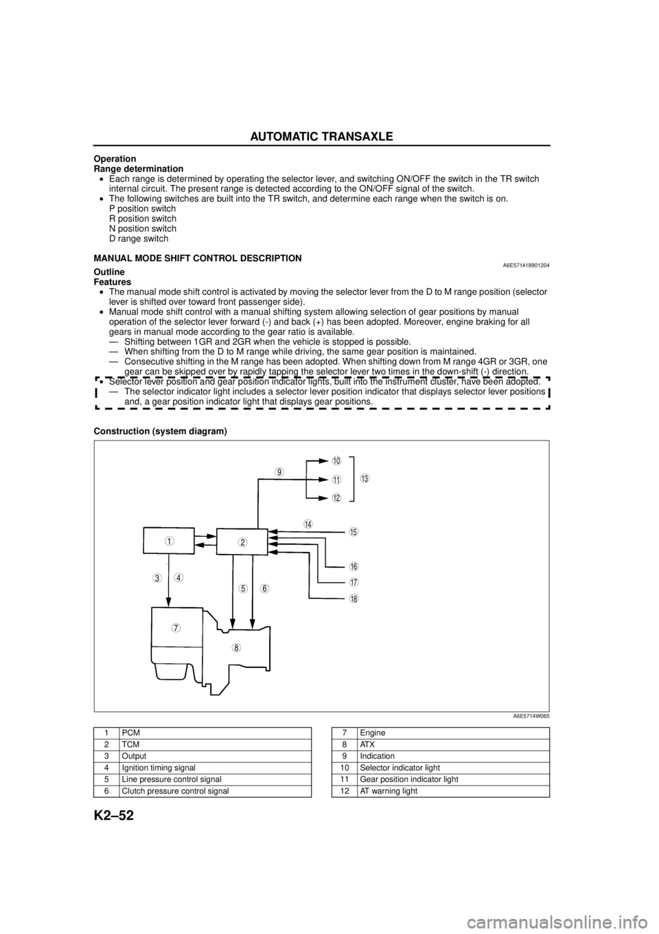
Construction (system diagram)
.
9
8
7
5
43
12
10
18
17
15
16
14
1311
12
6
A6E5714W065
1PCM
2TCM
3Output
4 Ignition timing signal
5 Line pressure control signal
6 Clutch pressure control signal7Engine
8ATX
9 Indication
10 Selector indicator light
11 Gear position indicator light
12 AT warning light
Page 514 of 909

AUTOMATIC TRANSAXLE
K2–99
K2
AUTOMATIC TRANSAXLE AND TRANSFER REMOVAL/INSTALLATIONA6E5714190902011. Disconnect the negative battery cable.
2. Remove the battery and battery tray.
3. Remove the aircleaner component. (See Sectin F.)
4. Remove the front tires and splash shield.
5. Remove the under cover.
6. Separate the steering shaft and steering hose. (See N–13 STEERING GEAR AND LINKAGE (4WD)
REMOVAL/INSTALLATION.)
7. Remove the front auto leveling sensor. (See Section T.)
8. Drain the ATF. (See K2–80 AUTOMATIC TRANSAXLE FLUID (ATF) REPLACEMENT.)
Warning
•Improperly jacking a transaxle is dangerous. It can slip off the jack and may cause serious injury.
Caution
•To prevent the torque converter and transaxle from separating, remove the transaxle without
tilting it toward the torque converter.
9. Remove in the order shown in the figure.
10. Install in the reverse order of removal.
11. Adjust the headlight zeroset. (See Section T.)
12. Add ATF to the specified level. (See K2–80 AUTOMATIC TRANSAXLE FLUID (ATF) REPLACEMENT.)
13. Carry out the mechanical system test. (See K2–72 MECHANICAL SYSTEM TEST.)
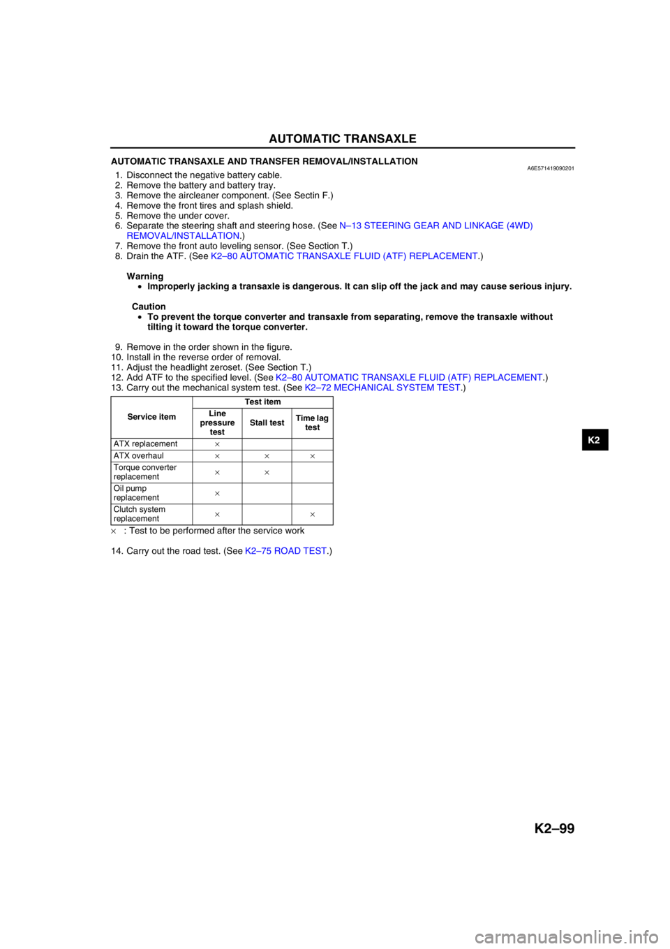
×: Test to be performed after the service work
14. Carry out the road test. (See K2–75 ROAD TEST.)
Service itemTest item
Line
pressure
testStall testTime lag
test
ATX replacement×
ATX overhaul×××
Torque converter
replacement××
Oil pump
replacement×
Clutch system
replacement××
Page 516 of 909

AUTOMATIC TRANSAXLE
K2–101
K2
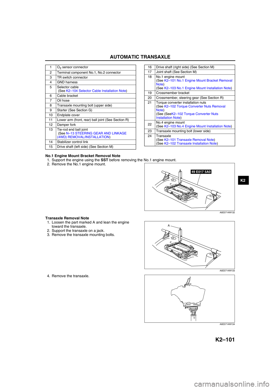
No.1 Engine Mount Bracket Removal Note
1. Support the engine using the SST before removing the No.1 engine mount.
2. Remove the No.1 engine mount.
Transaxle Removal Note
1. Loosen the part marked A and lean the engine
toward the transaxle.
2. Support the transaxle on a jack.
3. Remove the transaxle mounting bolts.
4. Remove the transaxle.
1O2 sensor connector
2 Terminal component No.1, No.2 connector
3 TR switch connector
4 GND harness
5 Selector cable
(See K2–104 Selector Cable Installation Note)
6 Cable bracket
7 Oil hose
8 Transaxle mounting bolt (upper side)
9 Starter (See Section G)
10 Endplate cover
11 Lower arm (front, rear) ball joint (See Section R)
12 Damper fork
13 Tie-rod end ball joint
(See N–13 STEERING GEAR AND LINKAGE
(4WD) REMOVAL/INSTALLATION)
14 Stabilizer control link
15 Drive shaft (left side) (See Section M)16 Drive shaft (right side) (See Section M)
17 Joint shaft (See Section M)
18 No.1 engine mount
(See K2–101 No.1 Engine Mount Bracket Removal
Note)
(See K2–103 No.1 Engine Mount Installation Note)
19 Crossmember bracket
20 Crossmember, steering gear (See Section R)
21 Torque converter installation nuts
(See K2–102 Torque Converter Nuts Removal
Note)
(See (SeeK2–102 Torque Converter Nuts
Installation Note)
22No.4 engine mount
(See K2–103 No.4 Engine Mount Installation Note)
23 Transaxle mounting bolt (lower side)
24 Transaxle
(See K2–101 Transaxle Removal Note)
(See K2–102 Transaxle Installation Note)
49 E017 5A0
A6E5714W132
A
A6E5714W133
A6E5714W134
Page 527 of 909

K2–112
AUTOMATIC TRANSAXLE
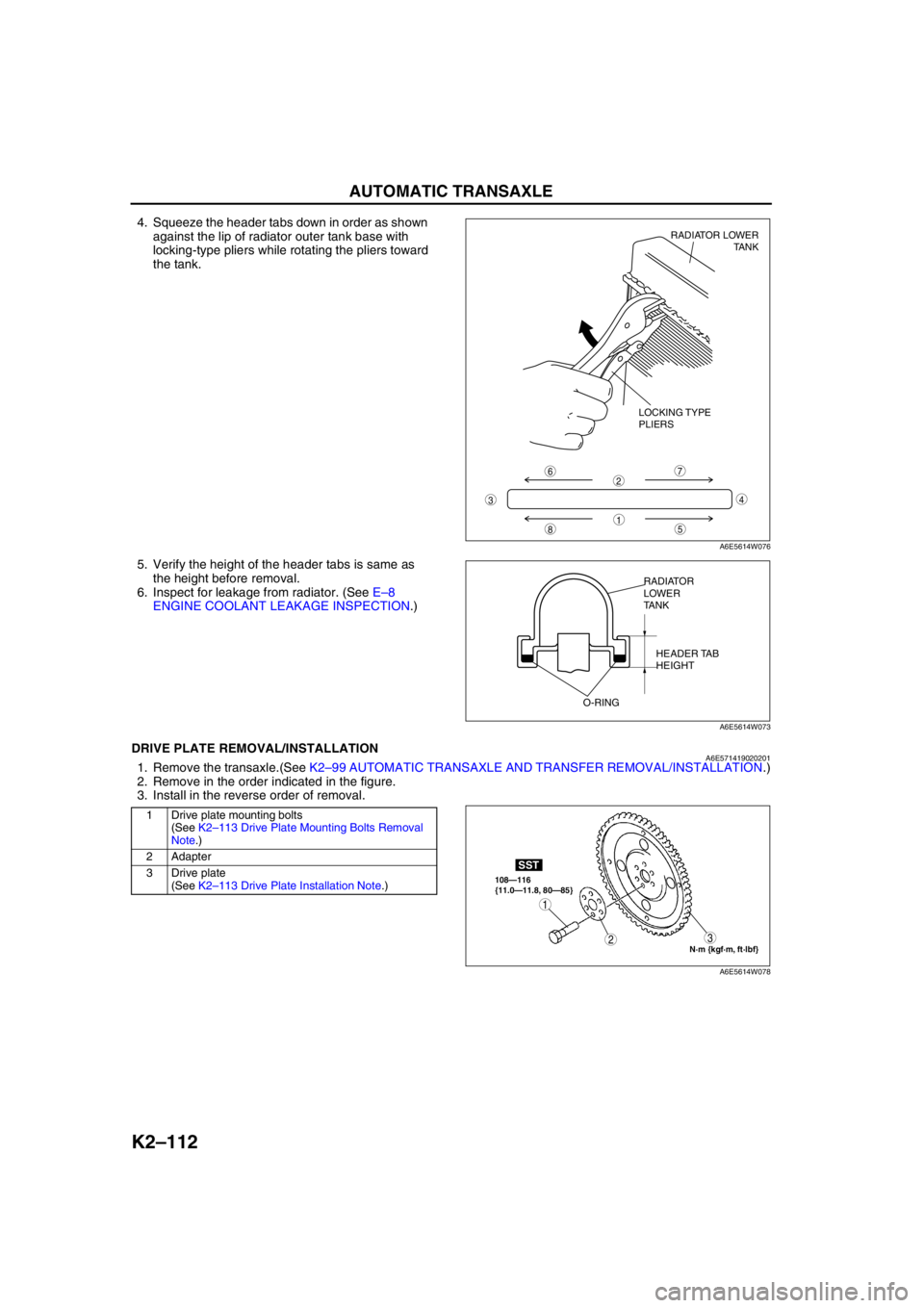
4. Squeeze the header tabs down in order as shown
against the lip of radiator outer tank base with
locking-type pliers while rotating the pliers toward
the tank.
5. Verify the height of the header tabs is same as
the height before removal.
6. Inspect for leakage from radiator. (See E–8
ENGINE COOLANT LEAKAGE INSPECTION.)
End Of SieDRIVE PLATE REMOVAL/INSTALLATIONA6E5714190202011. Remove the transaxle.(See K2–99 AUTOMATIC TRANSAXLE AND TRANSFER REMOVAL/INSTALLATION.)
2. Remove in the order indicated in the figure.
3. Install in the reverse order of removal.
.
8
7
5
43
6
1
2
LOCKING TYPE
PLIERSRADIATOR LOWER
TANK
A6E5614W076
RADIATOR
LOWER
TANK
HEADER TAB
HEIGHT
O-RING
A6E5614W073
1 Drive plate mounting bolts
(See K2–113 Drive Plate Mounting Bolts Removal
Note.)
2 Adapter
3 Drive plate
(See K2–113 Drive Plate Installation Note.)
N·m {kgf·m, ft·lbf} 108—116
{11.0—11.8, 80—85}
SST
3
1
2
A6E5614W078