wheel bolt torque MAZDA 6 2002 Workshop Manual Suplement
[x] Cancel search | Manufacturer: MAZDA, Model Year: 2002, Model line: 6, Model: MAZDA 6 2002Pages: 909, PDF Size: 17.16 MB
Page 400 of 909

H–6
CLUTCH UNIT
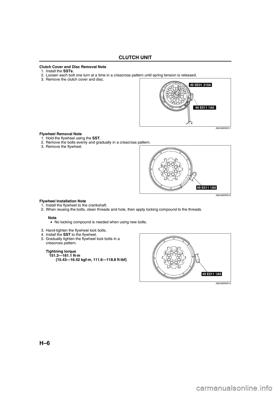
Clutch Cover and Disc Removal Note
1. Install the SSTs.
2. Loosen each bolt one turn at a time in a crisscross pattern until spring tension is released.
3. Remove the clutch cover and disc.
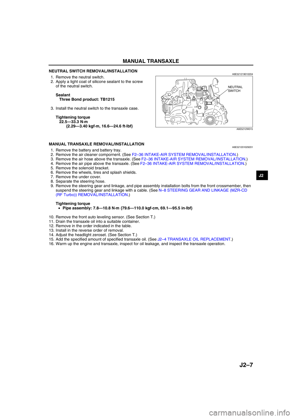
Flywheel Removal Note
1. Hold the flywheel using the SST.
2. Remove the bolts evenly and gradually in a crisscross pattern.
3. Remove the flywheel.
Flywheel Installation Note
1. Install the flywheel to the crankshaft.
2. When reusing the bolts, clean threads and hole, then apply locking compound to the threads.
Note
•No locking compound is needed when using new bolts.
3. Hand-tighten the flywheel lock bolts.
4. Install the SST to the flywheel.
5. Gradually tighten the flywheel lock bolts in a
crisscross pattern.
Tightning torque
151.3—161.1 N·m
{15.43—16.42 kgf·m, 111.6—118.8 ft·lbf}
49 SE01 310A
49 E011 1A0
A6E4920W011
49 E011 1A0
5
4
3
61
2
8
7
A6E4920W012
49 E011 1A0
5
4
3
61
2
8
7
A6E4920W013
Page 409 of 909

MANUAL TRANSAXLE
J2–7
J2
NEUTRAL SWITCH REMOVAL/INSTALLATIONA6E5212190102041. Remove the neutral switch.
2. Apply a light coat of silicone sealant to the screw
of the neutral switch.
Sealant
Three Bond product: TB1215
3. Install the neutral switch to the transaxle case.
Tightening torque
22.5—33.3 N·m
{2.29—3.40 kgf·m, 16.6—24.6 ft·lbf}
End Of Sie
MANUAL TRANSAXLE REMOVAL/INSTALLATIONA6E5212010292011. Remove the battery and battery tray.
2. Remove the air cleaner compornent. (See F2–36 INTAKE-AIR SYSTEM REMOVAL/INSTALLATION.)
3. Remove the air hose above the transaxle. (See F2–36 INTAKE-AIR SYSTEM REMOVAL/INSTALLATION.)
4. Remove the air pipe above the transaxle. (See F2–36 INTAKE-AIR SYSTEM REMOVAL/INSTALLATION.)
5. Remove the solenoid bracket.
6. Remove the wheels, tires and splash shields.
7. Remove the under cover.
8. Separate the steering hose.
9. Remove the steering gear and linkage, and pipe assembly installation bolts from the front crossmember, then
suspend the steering gear and linkage with a cable. (See N–8 STEERING GEAR AND LINKAGE (MZR-CD
(RF Turbo)) REMOVAL/INSTALLATION.)
Tightening torque
•Pipe assembly: 7.8—10.8 N·m {79.6—110.0 kgf·cm, 69.1—95.5 in·lbf}
10. Remove the front auto leveling sensor. (See Section T.)
11. Drain the transaxle oil into a suitable container.
12. Remove in the order indicated in the table.
13. Install in the reverse order of removal.
14. Adjust the headlight zeroset. (See Section T.)
15. Add the specified amount of specified transaxle oil. (See J2–4 TRANSAXLE OIL REPLACEMENT.)
16. Warm up the engine and transaxle, inspect for oil leakage, and inspect the transaxle operation.
NEUTRAL
SWITCH
A6E5212W015
Page 722 of 909

N–8
ENGINE SPEED SENSING POWER STEERING
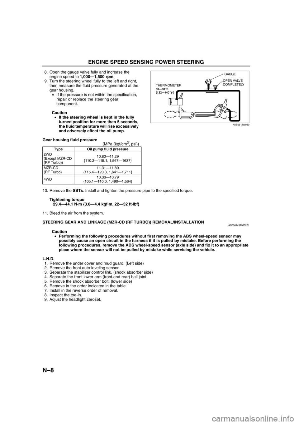
8. Open the gauge valve fully and increase the
engine speed to 1,000—1,500 rpm.
9. Turn the steering wheel fully to the left and right,
then measure the fluid pressure generated at the
gear housing.
•If the pressure is not within the specification,
repair or replace the steering gear
component.
Caution
•If the steering wheel is kept in the fully
turned position for more than 5 seconds,
the fluid temperature will rise excessively
and adversely affect the oil pump.
Gear housing fluid pressure
(MPa {kgf/cm
2, psi})
10. Remove the SSTs. Install and tighten the pressure pipe to the specified torque.
Tightening torque
29.4—44.1 N·m {3.0—4.4 kgf·m, 22—32 ft·lbf}
11. Bleed the air from the system.
End Of Sie
STEERING GEAR AND LINKAGE (MZR-CD (RF TURBO)) REMOVAL/INSTALLATIONA6E661432960201
Caution
•Performing the following procedures without first removing the ABS wheel-speed sensor may
possibly cause an open circuit in the harness if it is pulled by mistake. Before performing the
following procedures, remove the ABS wheel-speed sensor (axle side) and fix it to an appropriate
place where the sensor will not be pulled by mistake while servicing the vehicle.
L.H.D.
1. Remove the under cover and mud guard. (Left side)
2. Remove the front auto leveling sensor.
3. Separate the stabilizer control link. (shock absorber side)
4. Separate the front lower arm (front and rear) ball joint.
5. Remove the shock absorber bolt. (lower side)
6. Remove in the order indicated in the table.
7. Install in the reverse order of removal.
8. Inspect the toe-in.
9. Adjust the headlight zeroset.
Type Oil pump fluid pressure
2WD
(Except MZR-CD
(RF Turbo))10.80—11.29
{110.2—115.1, 1,567—1637}
MZR-CD
(RF Turbo)11.31—11.80
{115.4—120.3, 1,641—1,711}
4WD10.30—10.79
{105.1—110.0, 1,490—1,564}
THERMOMETER50—60
{122—140 }°
°F
GAUGE
OPEN VALVE
COMPLETELY
A6E0612W080
Page 771 of 909

WHEEL ALIGNMENT
R–9
R
Total Toe-in Adjustment
1. Center the steering wheel and confirm that the vehicle wheels/tires are pointing straight.
2. Loosen the left and right tie-rod end locknuts and turn the tie-rods equally. Both tie rods are right threaded, so
turning the right tie-rod toward the front of the vehicle and the left toward the rear increases toe-in.
Note
•Turning both tie-rods one complete turn changes toe-in by about 6 mm {0.24 in} (0°36').
3. Tighten the tie-rod end locknuts to the specified torque.
Tightening torque
68.6—98.0 N·m {7.00—9.99 kgf·m, 50.6—72.2 ft·lbf}
4. Verify that the boot is not twisted, and install the boot clamp.
End Of Sie
REAR WHEEL ALIGNMENT (WGN)A6E741201016201Specification (Unloaded)*1
2WD
*
1: Engine coolant and engine oil are at specified level. Spare tire, jack and tools are in designated position.
*2: Difference between left and right must not exceed 1°30'.*3: Distance between wheel center and fender brim is 407 mm {16.02 in} (reference value).
4WD
*
1: Engine coolant and engine oil are at specified level. Spare tire, jack and tools are in designated position.
*2: Difference between left and right must not exceed 1°30'.
Note
•Adjust the toe-in after adjusting the camber.
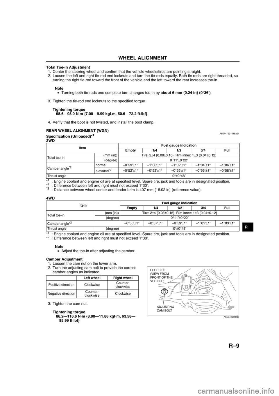
Camber Adjustment
1. Loosen the cam nut on the lower arm.
2. Turn the adjusting cam bolt to provide the correct
camber angles as indicated.
3. Tighten the cam nut.
Tightening torque
86.2—116.6 N·m {8.80—11.88 kgf·m, 63.58—
85.99 ft·lbf}
ItemFuel gauge indication
Empty 1/4 1/2 3/4 Full
Total toe-in(mm {in}) Tire: 2±4 {0.08±0.16}, Rim inner: 1±3 {0.04±0.12}
(degree) 0°11′±0°22′
Camber angle
*2 normal–0°59′±1°–1°00′±1°–1°02′±1°–1°04′±1°–1°06′±1°
elevated
*3–0°52′±1°–0°53′±1°–0°55′±1°–0°56′±1°–0°58′±1°
Thrust angle 0°±0°48′
ItemFuel gauge indication
Empty 1/4 1/2 3/4 Full
Total toe-in(mm {in}) Tire: 2±4 {0.08±0.16}, Rim inner: 1±3 {0.04±0.12}
(degree) 0°11′±0°22′
Camber angle*
2 –0°55′±1°–0°57′±1°–0°59′±1°–1°01′±1°–1°03′±1°
Thrust angle (degree) 0°±0°48′
Left wheel Right wheel
Positive direction ClockwiseCounter-
clockwise
Negative directionCounter-
clockwiseClockwise
LEFT SIDE
(VIEW FROM
FRONT OF THE
VEHICLE)
ADJUSTING
CAM BOLT
A6E7412W003
Page 778 of 909

R–16
REAR SUSPENSION
Bolt (Trailing Link Front Side) Removal Note
1. Support the trailing link with a jack.
Caution
•Removing the trailing link is dangerous.
The trailing link could fall and cause
serious injury or death. Verify that the
jack securely supports the trailing link.
2. Remove the bolts (trailing link front side).
Bolt (Lateral Link Outer Side) Removal Note
1. Loosen the bolt (lateral link inner side).
2. Remove the bolt (lateral link outer side).
Bolt (Lateral Link Outer Side) Installation Note
1. Tighten the bolt (lateral link outer side).
2. Tighten the bolt (lateral link inner side).
Tightening torque
86.2—116.6 N·m {8.80—11.88 kgf·m, 63.58—85.99 ft·lbf}
Bolt (Trailing Link Front Side) Installation Note
1. Support the trailing link with a jack.
2. Tighten the bolts (trailing link front side).
End Of SieREAR CROSSMEMBER REMOVAL/INSTALLATION (4WD)A6E741628400201
Caution
•Performing the following procedures without first removing the ABS wheel-speed sensor may
possibly cause an open circuit in the harness if it is pulled by mistake. Before performing the
following procedures, remove the ABS wheel-speed sensor (axle side) and fix it to an appropriate
place where the sensor will not be pulled by mistake while servicing the vehicle.
1. Remove the rear auto leveling sensor and harness.
(See T–20 REAR AUTO LEVELING SENSOR REMOVAL/INSTALLATION.)
2. Remove the middle pipe.
(See F1–30 EXHAUST SYSTEM REMOVAL/INSTALLATION.)
3. Remove in the order indicated in the table.
4. Install in the reverse order of removal.
5. Adjust the headlight zeroset.
6. Inspect the rear wheel alignment.
(See R–9 REAR WHEEL ALIGNMENT (WGN).)
JACK
A6E74162010
JACK
A6E74162010