battery replacement MAZDA 6 2002 Workshop Manual Suplement
[x] Cancel search | Manufacturer: MAZDA, Model Year: 2002, Model line: 6, Model: MAZDA 6 2002Pages: 909, PDF Size: 17.16 MB
Page 40 of 909
COMPRESSION PRESSURE, TIMING BELT
B2–9
B2
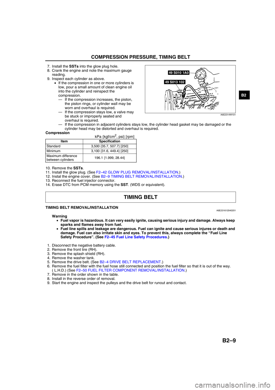
7. Install the SSTs into the glow plug hole.
8. Crank the engine and note the maximum gauge
reading.
9. Inspect each cylinder as above.
•If the compression in one or more cylinders is
low, pour a small amount of clean engine oil
into the cylinder and reinspect the
compression.
—If the compression increases, the piston,
the piston rings, or cylinder wall may be
worn and overhaul is required.
—If the compression stays low, a valve may
be stuck or improperly seated and
overhaul is required.
—If the compression in adjacent cylinders stays low, the cylinder head gasket may be damaged or the
cylinder head may be distorted and overhaul is required.
Compression
kPa {kgf/cm
2, psi} [rpm]
10. Remove the SSTs.
11. Install the glow plug. (See F2–42 GLOW PLUG REMOVAL/INSTALLATION.)
12. Instal the engine cover. (See B2–9 TIMING BELT REMOVAL/INSTALLATION.)
13. Reconnect the fuel injector connector.
14. Erase DTC from PCM memory using the SST. (WDS or equivalent).
End Of Sie
TIMING BELT REMOVAL/INSTALLATIONA6E231612040201
Warning
•Fuel vapor is hazardous. It can very easily ignite, causing serious injury and damage. Always keep
sparks and flames away from fuel.
•Fuel line spills and leakage are dangerous. Fuel can ignite and cause serious injures or death and
damage. Fuel can also irritate skin and eyes. To prevent this, always complete the “Fuel Line
Safety Procedure”. (See F2–45 Fuel Line Safety Procedures.)
1. Disconnect the negative battery cable.
2. Remove the front tire (RH).
3. Remove the splash shield (RH).
4. Remove the washer tank.
5. Remove the drive belt. (See B2–4 DRIVE BELT REPLACEMENT.)
6. Remove the fuel filter with the fuel hose still connected and position the fuel filter so that it is out of the way.
( L.H.D.) (See F2–50 FUEL FILTER COMPONENT REMOVAL/INSTALLATION.)
7. Remove in the order shown in the table.
8. Install in the reverse order of removal.
9. Start the engine and inspect the pulleys and the drive belt for runout and contact.
Item Specification
Standard 3,500 {35.7, 507.7} [250]
Minimum 3,100 {31.6, 449.4} [250]
Maximum difference
between cylinders196.1 {1.999, 28.44}
49 S010 1A0
49 S013 102
A6E2314W101
TIMING BELT
Page 73 of 909
OIL FILTER, OIL COOLER
D–9
D
OIL FILTER REPLACEMENTA6E331414300201MZR-CD (RF Turbo)
1. Disconnect the negative battery cable.
2. Remove the under cover.
3. Remove the oil filter using the oil filter wrench.
4. Use a clean rag to wipe off the mounting surface
on the oil filter.
5. Apply clean engine oil to the O-ring of a new oil
filter.
6. Using the oil filter wrench, tighten the filter
according to the installation procedure indicated
on the side of the filter or packing box.
7. Start the engine and inspect for oil leakage.
•If the oil leaks, specify the faulty part and
repair or replace it.
8. Inspect the oil level. (See D–8 ENGINE OIL
INSPECTION.)
9. Install the under cover.
End Of Sie
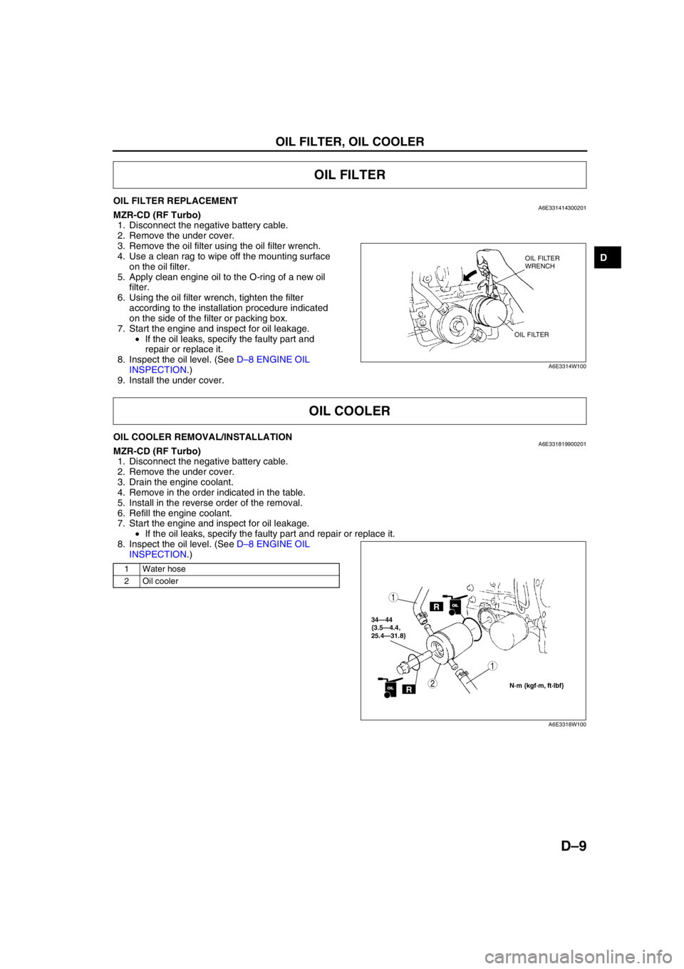
OIL COOLER REMOVAL/INSTALLATIONA6E331819900201MZR-CD (RF Turbo)
1. Disconnect the negative battery cable.
2. Remove the under cover.
3. Drain the engine coolant.
4. Remove in the order indicated in the table.
5. Install in the reverse order of the removal.
6. Refill the engine coolant.
7. Start the engine and inspect for oil leakage.
•If the oil leaks, specify the faulty part and repair or replace it.
8. Inspect the oil level. (See D–8 ENGINE OIL
INSPECTION.)
.
End Of Sie
OIL FILTER
OIL FILTER
WRENCH
OIL FILTER
A6E3314W100
OIL COOLER
1 Water hose
2 Oil cooler
ROILOIL
34—44
{3.5—4.4,
25.4—31.8}
1
2N·m {kgf·m, ft·lbf}ROILOIL
1
A6E3318W100
Page 74 of 909
D–10
OIL PAN
OIL PAN REMOVAL/INSTALLATIONA6E332010040201MZR-CD (RF Turbo)
Warning
•Hot engines and engines oil can cause severe burns. Turn off the engine and wait until it and the
engine oil have cooled.
1. Disconnect the negative battery cable.
2. Remove the under cover.
3. Drain the engine oil. (See D–8 ENGINE OIL REPLACEMENT.)
4. Remove the lower radiator hose assembly under the oil pan with the cooling hose still connected. Position the
lower radiator hose assembly so that it is out of the way.
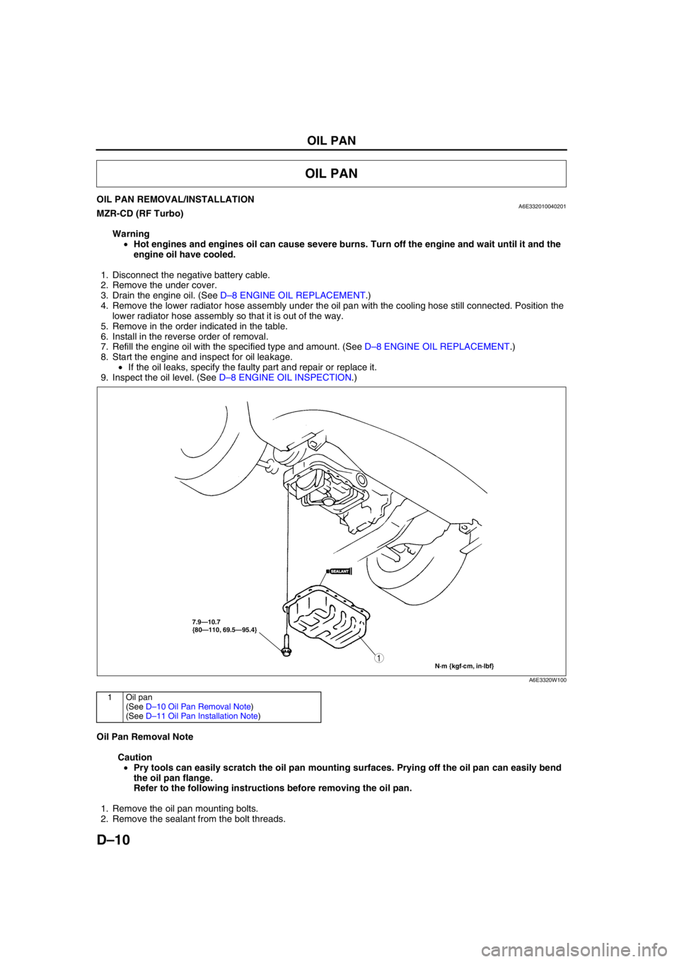
5. Remove in the order indicated in the table.
6. Install in the reverse order of removal.
7. Refill the engine oil with the specified type and amount. (See D–8 ENGINE OIL REPLACEMENT.)
8. Start the engine and inspect for oil leakage.
•If the oil leaks, specify the faulty part and repair or replace it.
9. Inspect the oil level. (See D–8 ENGINE OIL INSPECTION.)
.
Oil Pan Removal Note
Caution
•Pry tools can easily scratch the oil pan mounting surfaces. Prying off the oil pan can easily bend
the oil pan flange.
Refer to the following instructions before removing the oil pan.
1. Remove the oil pan mounting bolts.
2. Remove the sealant from the bolt threads.
OIL PAN
7.9—10.7
{80—110, 69.5—95.4}
N·m {kgf·cm, in·lbf}
1
SEALANTSEALANT
A6E3320W100
1Oil pan
(See D–10 Oil Pan Removal Note)
(See D–11 Oil Pan Installation Note)
Page 189 of 909
INTAKE-AIR SYSTEM
F2–37
F2Air Pipe Removal Note
1. Remove the battery and the battery tray before removing the air pipe. (See G–5 BATTERY REMOVAL/
INSTALLATION.)
Intake Manifold Removal Note
1. Remove the supply pump before removing the intake manifold. (See F2–53 SUPPLY PUMP REMOVAL/
INSTALLATION.)
2. Remove the EGR valve before removing the intake manifold. (See F2–59 EGR VALVE REMOVAL/
INSTALLATION.)
Air Cleaner Case Installation Note
Note
•Before assembling the air cleaner, verify that the rubber mounts have not fallen off from the air cleaner
bracket (3 locations).
•Always install the air cleaner case using the following procedure.
•When inserting the rubber mounts into the air cleaner case, soapy water can be applied.
1. Verify that the rubber mounts are set in the air cleaner bracket (3 locations).
2. Install the projections on the frame side (2 locations).
3. Verify that the projections on the frame side are installed securely.
4. Install the projection on the engine side (remaining location).
5. Verify that the projection on the engine side installed securely.
End Of Sie
AIR CLEANER ELEMENT INSPECTIONA6E4010010052041. Remove the air cleaner element. (See F2–36 INTAKE-AIR SYSTEM REMOVAL/INSTALLATION.)
2. Verify that the air cleaner element surface is free of dirt.
•If there is dirt present, use an air gun or similar tool to clean the element.
•If the replacement time limit has passed, replace the element.
End Of Sie
1 Vacuum hose
2 Air hose
3 Air cleaner cover
4 Air cleaner element
5Air cleaner case
(See F2–37 Air Cleaner Case Installation Note)
6 MAF/IAT sensor
7Air pipe
(See F2–37 Air Pipe Removal Note)
8 Vacuum pipe
9 Air hose
10 Air pipe11 Air hose
12 Air pipe
13 Boost sensor
14 IAT sensor No. 2
15 Air pipe
16 Air hose
17 Air duct
18 Charge air cooler
19 Vacuum hose (Intake shutter valve actuator)
20 Vacuum hose (VSC shutter valve actuator)
21Intake manifold
(See F2–37 Intake Manifold Removal Note)
Page 228 of 909
F2–76
CONTROL SYSTEM
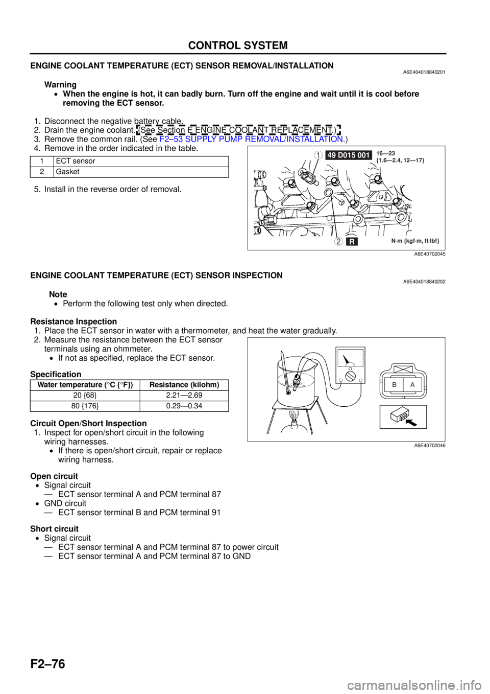
ENGINE COOLANT TEMPERATURE (ECT) SENSOR REMOVAL/INSTALLATIONA6E404018840201
Warning•When the engine is hot, it can badly burn. Turn off the engine and wait until it is cool before
removing the ECT sensor.
1. Disconnect the negative battery cable.
2. Drain the engine coolant. (See Section E ENGINE COOLANT REPLACEMENT.)
3. Remove the common rail. (See F2–53 SUPPLY PUMP REMOVAL/INSTALLATION .)
4. Remove in the order indicated in the table.
5. Install in the reverse order of removal.
End Of Sie
ENGINE COOLANT TEMPERATURE (ECT) SENSOR INSPECTIONA6E404018840202
Note
• Perform the following test only when directed.
Resistance Inspection 1. Place the ECT sensor in water with a thermometer, and heat the water gradually.
2. Measure the resistance between the ECT sensor terminals using an ohmmeter.
• If not as specified, replace the ECT sensor.
Specification
Circuit Open/Short Inspection 1. Inspect for open/short circuit in the following
wiring harnesses.• If there is open/short circuit, repair or replace
wiring harness.
Open circuit • Signal circuit
— ECT sensor terminal A and PCM terminal 87
• GND circuit
— ECT sensor terminal B and PCM terminal 91
Short circuit • Signal circuit
— ECT sensor terminal A and PCM terminal 87 to power circuit
— ECT sensor terminal A and PCM terminal 87 to GND
End Of Sie
1ECT sensor
2Gasket149 D015 001
N·m {kgf·m, ft·lbf}
16—23
{1.6—2.4, 12—17}2R
A6E40702045
Water temperature (
°C { °F}) Resistance (kilohm)
20 {68} 2.21—2.69
80 {176} 0.29—0.34A
B
A6E40702046
Page 390 of 909
CHARGING SYSTEM
G–7
G
1. Remove the battery from vehicle and place it in a pan of water.
2. Connect a battery charger to the battery.
3. Adjust the charging current as follows.
4. After the battery has been recharged, measure
the battery positive voltage and verify that the
battery keeps specified voltage for more than 1 h.
•If not as specified, replace the battery.
Specification
Above 12.4 V
End Of Sie
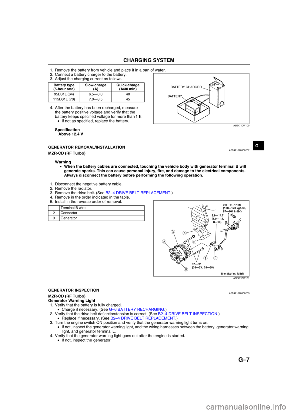
GENERATOR REMOVAL/INSTALLATIONA6E471018300202MZR-CD (RF Turbo)
Warning
•When the battery cables are connected, touching the vehicle body with generator terminal B will
generate sparks. This can cause personal injury, fire, and damage to the electrical components.
Always disconnect the battery before performing the following operation.
1. Disconnect the negative battery cable.
2. Remove the radiator.
3. Remove the drive belt. (See B2–4 DRIVE BELT REPLACEMENT.)
4. Remove in the order indicated in the table.
5. Install in the reverse order of removal.
End Of SieGENERATOR INSPECTIONA6E471018300203MZR-CD (RF Turbo)
Generator Warning Light
1. Verify that the battery is fully charged.
•Charge if necessary. (See G–6 BATTERY RECHARGING.)
2. Verify that the drive belt deflection/tension is correct. (See B2–4 DRIVE BELT INSPECTION.)
•Replace if necessary. (See B2–4 DRIVE BELT REPLACEMENT.)
3. Turn the engine switch ON position and verify that the generator warning light turns on.
•If not, inspect the generator warning light, and the wiring harnesses between the battery, generator warning
light, and generator terminal L.
4. Verify that the generator warning light goes out after the engine is started.
•If not, inspect the generator.
Battery type
(5-hour rate)Slow-charge
(A)Quick-charge
(A/30 min)
95D31L (64) 6.5—8.0 40
115D31L (70) 7.0—8.5 45BATTERY CHARGER
BATTERY
A6E4710W100
1 Terminal B wire
2 Connector
3 Generator
3
12
A
B
A
B
9.8—14.7
{1.0—1.4,
8—10}
N·m {kgf·m, ft·lbf}
37—52
{38—53, 28—38}
9.8—11.7 N·m
{100—120 kgf·cm,
87—104 in·lbf}
A6E4710W101
Page 391 of 909
G–8
CHARGING SYSTEM
Generator
Voltage
1. Verify that the battery is fully charged.
•Charge if necessary. (See G–6 BATTERY RECHARGING.)
2. Inspect the drive belt deflection/tension.
(See B2–4 DRIVE BELT INSPECTION.)
•Replace if necessary. (See B2–4 DRIVE BELT REPLACEMENT.)
3. Turn off all electrical loads.
4. Turn the engine switch to start the engine and verify that the generator rotates smoothly without any noise
while the engine is running.
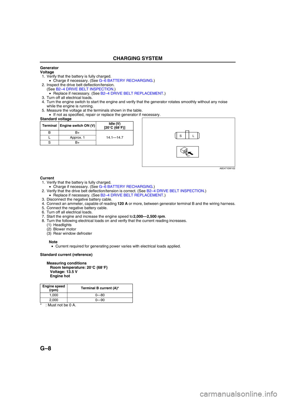
5. Measure the voltage at the terminals shown in the table.
•If not as specified, repair or replace the generator if necessary.
Standard voltage
Current
1. Verify that the battery is fully charged.
•Charge if necessary. (See G–6 BATTERY RECHARGING.)
2. Verify that the drive belt deflection/tension is correct. (See B2–4 DRIVE BELT INSPECTION.)
•Replace if necessary. (See B2–4 DRIVE BELT REPLACEMENT.)
3. Disconnect the negative battery cable.
4. Connect an ammeter, capable of reading 120 A or more, between generator terminal B and the wiring harness.
5. Connect the negative battery cable.
6. Turn off all electrical loads.
7. Start the engine and increase the engine speed to 2,000—2,500 rpm.
8. Turn the following electrical loads on and verify that the current reading increases.
(1) Headlights
(2) Blower motor
(3) Rear window defroster
Note
•Current required for generating power varies with electrical loads applied.
Standard current (reference)
Measuring conditions
Room temperature: 20°C {68°F}
Voltage: 13.5 V
Engine hot
* : Must not be 0 A.
End Of Sie
Terminal Engine switch ON (V)Idle (V)
[20°C {68°F}]
BB+
14.1—14.7 LApprox. 1
SB+
SL
A6E4710W102
Engine speed
(rpm)Terminal B current (A)*
1,000 0—80
2,000 0—90
Page 409 of 909
MANUAL TRANSAXLE
J2–7
J2
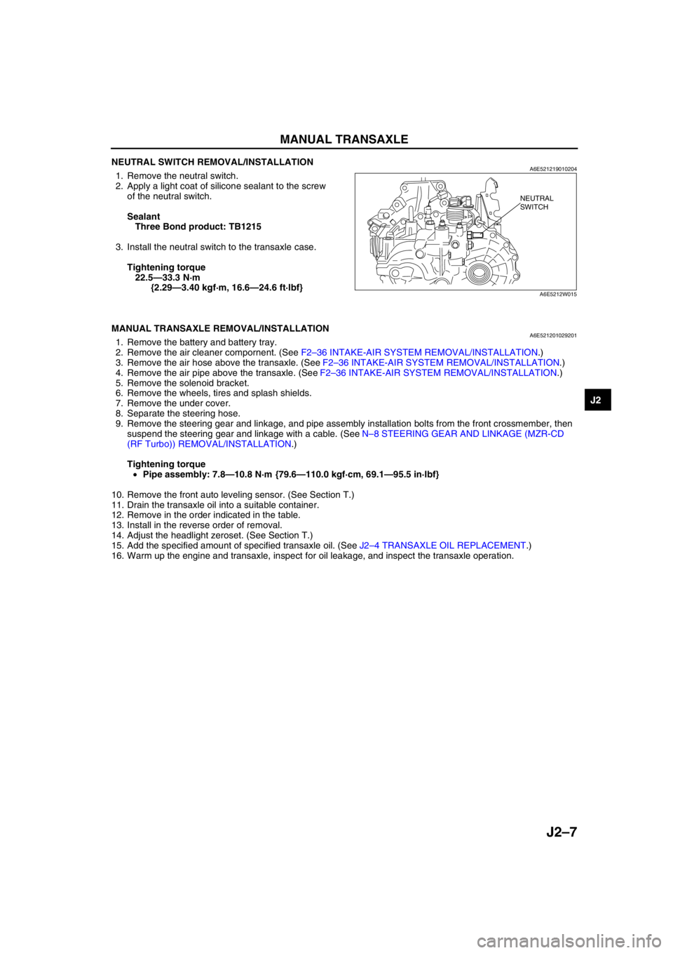
NEUTRAL SWITCH REMOVAL/INSTALLATIONA6E5212190102041. Remove the neutral switch.
2. Apply a light coat of silicone sealant to the screw
of the neutral switch.
Sealant
Three Bond product: TB1215
3. Install the neutral switch to the transaxle case.
Tightening torque
22.5—33.3 N·m
{2.29—3.40 kgf·m, 16.6—24.6 ft·lbf}
End Of Sie
MANUAL TRANSAXLE REMOVAL/INSTALLATIONA6E5212010292011. Remove the battery and battery tray.
2. Remove the air cleaner compornent. (See F2–36 INTAKE-AIR SYSTEM REMOVAL/INSTALLATION.)
3. Remove the air hose above the transaxle. (See F2–36 INTAKE-AIR SYSTEM REMOVAL/INSTALLATION.)
4. Remove the air pipe above the transaxle. (See F2–36 INTAKE-AIR SYSTEM REMOVAL/INSTALLATION.)
5. Remove the solenoid bracket.
6. Remove the wheels, tires and splash shields.
7. Remove the under cover.
8. Separate the steering hose.
9. Remove the steering gear and linkage, and pipe assembly installation bolts from the front crossmember, then
suspend the steering gear and linkage with a cable. (See N–8 STEERING GEAR AND LINKAGE (MZR-CD
(RF Turbo)) REMOVAL/INSTALLATION.)
Tightening torque
•Pipe assembly: 7.8—10.8 N·m {79.6—110.0 kgf·cm, 69.1—95.5 in·lbf}
10. Remove the front auto leveling sensor. (See Section T.)
11. Drain the transaxle oil into a suitable container.
12. Remove in the order indicated in the table.
13. Install in the reverse order of removal.
14. Adjust the headlight zeroset. (See Section T.)
15. Add the specified amount of specified transaxle oil. (See J2–4 TRANSAXLE OIL REPLACEMENT.)
16. Warm up the engine and transaxle, inspect for oil leakage, and inspect the transaxle operation.
NEUTRAL
SWITCH
A6E5212W015
Page 514 of 909
AUTOMATIC TRANSAXLE
K2–99
K2
AUTOMATIC TRANSAXLE AND TRANSFER REMOVAL/INSTALLATIONA6E5714190902011. Disconnect the negative battery cable.
2. Remove the battery and battery tray.
3. Remove the aircleaner component. (See Sectin F.)
4. Remove the front tires and splash shield.
5. Remove the under cover.
6. Separate the steering shaft and steering hose. (See N–13 STEERING GEAR AND LINKAGE (4WD)
REMOVAL/INSTALLATION.)
7. Remove the front auto leveling sensor. (See Section T.)
8. Drain the ATF. (See K2–80 AUTOMATIC TRANSAXLE FLUID (ATF) REPLACEMENT.)
Warning
•Improperly jacking a transaxle is dangerous. It can slip off the jack and may cause serious injury.
Caution
•To prevent the torque converter and transaxle from separating, remove the transaxle without
tilting it toward the torque converter.
9. Remove in the order shown in the figure.
10. Install in the reverse order of removal.
11. Adjust the headlight zeroset. (See Section T.)
12. Add ATF to the specified level. (See K2–80 AUTOMATIC TRANSAXLE FLUID (ATF) REPLACEMENT.)
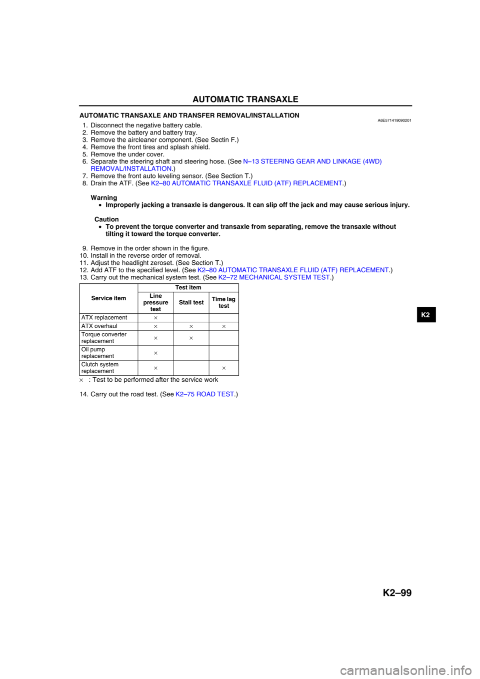
13. Carry out the mechanical system test. (See K2–72 MECHANICAL SYSTEM TEST.)
×: Test to be performed after the service work
14. Carry out the road test. (See K2–75 ROAD TEST.)
Service itemTest item
Line
pressure
testStall testTime lag
test
ATX replacement×
ATX overhaul×××
Torque converter
replacement××
Oil pump
replacement×
Clutch system
replacement××
Page 521 of 909
K2–106
AUTOMATIC TRANSAXLE
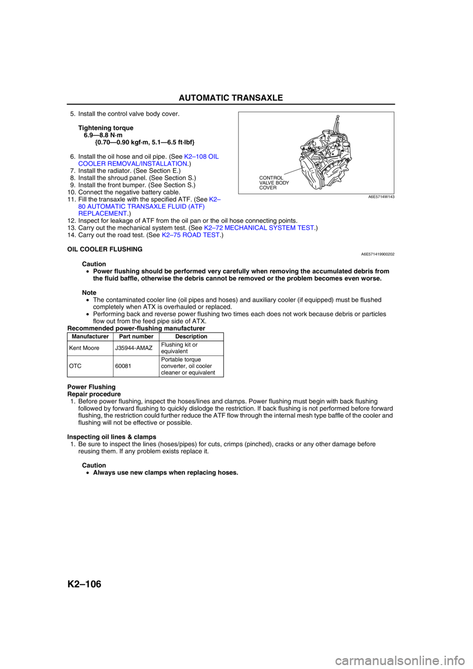
5. Install the control valve body cover.
Tightening torque
6.9—8.8 N·m
{0.70—0.90 kgf·m, 5.1—6.5 ft·lbf}
6. Install the oil hose and oil pipe. (See K2–108 OIL
COOLER REMOVAL/INSTALLATION.)
7. Install the radiator. (See Section E.)
8. Install the shroud panel. (See Section S.)
9. Install the front bumper. (See Section S.)
10. Connect the negative battery cable.
11. Fill the transaxle with the specified ATF. (See K2–
80 AUTOMATIC TRANSAXLE FLUID (ATF)
REPLACEMENT.)
12. Inspect for leakage of ATF from the oil pan or the oil hose connecting points.
13. Carry out the mechanical system test. (See K2–72 MECHANICAL SYSTEM TEST.)
14. Carry out the road test. (See K2–75 ROAD TEST.)
End Of Sie
OIL COOLER FLUSHINGA6E571419900202
Caution
•Power flushing should be performed very carefully when removing the accumulated debris from
the fluid baffle, otherwise the debris cannot be removed or the problem becomes even worse.
Note
•The contaminated cooler line (oil pipes and hoses) and auxiliary cooler (if equipped) must be flushed
completely when ATX is overhauled or replaced.
•Performing back and reverse power flushing two times each does not work because debris or particles
flow out from the feed pipe side of ATX.
Recommended power-flushing manufacturer
Power Flushing
Repair procedure
1. Before power flushing, inspect the hoses/lines and clamps. Power flushing must begin with back flushing
followed by forward flushing to quickly dislodge the restriction. If back flushing is not performed before forward
flushing, the restriction could further reduce the ATF flow through the internal mesh type baffle of the cooler and
flushing will not be effective or possible.
Inspecting oil lines & clamps
1. Be sure to inspect the lines (hoses/pipes) for cuts, crimps (pinched), cracks or any other damage before
reusing them. If any problem exists replace it.
Caution
•Always use new clamps when replacing hoses.
CONTROL
VALVE BODY
COVER
A6E5714W143
Manufacturer Part number Description
Kent Moore J35944-AMAZFlushing kit or
equivalent
OTC 60081Portable torque
converter, oil cooler
cleaner or equivalent