oil MAZDA 626 1987 Workshop Manual
[x] Cancel search | Manufacturer: MAZDA, Model Year: 1987, Model line: 626, Model: MAZDA 626 1987Pages: 1865, PDF Size: 94.35 MB
Page 316 of 1865

INSPECTION, ENGINE OIL 2A
86U02X-004
INSPECTION
ENGINE OIL
1. Be sure the vehicle is on level ground.
2. Warm up the engine to normal operating temper-
ature and stop it.
3. Wait for five minutes.
4. Remove the oil level gauge and check the oil lev-
el and condition.
5. Add or replace oil if necessary.
Note
The distance between the L and F marks on
the level gauge represents 1.0 liter (1.06 US
qt, 0.88 Imp qt).
OIL PRESSURE
1. Remove the oil pressure switch.
69G02A-006
76G02A-005
86U02X-006
2. Screw the SST into the pressure switch installa-
tion hole.
3. Warm up the engine to normal operating tem-
perature.
4. Run the engine at 3,000 rpm, and note the gauge
reading.
Oil pressure:
343—441 kPa
(3.5—4.5 kg/cm2, 50—64 psi)...DOHC 2g4 392 kPa
(3.0—4.0 kg/cm2, 43—57 psi)...SOHC
5. If the pressure is not as specified, check for the
cause, and repair if necessary.
(Refer to Troubleshooting Guide.)
ENGINE OIL
REPLACEMENT
1. Warm up the engine to the normal operating tem-
perature and stop it.
2. Remove the oil filler cap and the oil pan drain plug.
3. Drain the oil into a suitable container.
Warning
Be careful when draining, the oil is very hot.
2A-5
Page 317 of 1865

2A OIL FILTER, OIL COOLER
j
F
k
4
4. Install the drain plug and a new gasket.
5. Refill the engine with the specified type and amount
of oil.
6. Refit the oil filler cap.
Oil pan capacity:
3.6 liters (3.8 US qt, 3.2 Imp qt)
7. Recheck the oil level after the engine has been run.
76G02A-006
TbJ
r
86U02X-008
76G02A-007
0
A
if \ lO
/O
f \ 11 • V jJ
VJ f .fa,-
n D
©
76G02A-008
OIL FILTER
REPLACEMENT
1. Remove the oil filter with a suitable wrench.
2. Use a clean rag to wipe off the mounting surface
on the engine.
3. Apply a small amount of engine oil to the rubber
seal of the new filter.
Warning
Be careful that the engine and filter are very
hot.
4. (DOHC)
Install the oil filter until the rubber seal contacts the
base and then tighten the filter
1
and
1
/6 turn with
a wrench.
(SOHC)
Install the oil filter and tighten it by hand only. Do
not use a wrench.
5. Start the engine and inspect around the filter seal
for leaks.
6. Check the oil level and add oil if necessary.
Oil filter capacity:
0.20 liters (0.21 US qt, 0.18 Imp qt)...DOHC
0.30 liters (0.32 US qt, 0.26 Imp qt)...SOHC
OIL
COOLER
(DOHC, 12-valve,
ECE
8-valve)
REMOVAL AND INSTALLATION
Remove in the sequence shown in the figure.
Install in the reverse order of removal.
1. Water hose
2. Oil filter
3. Nut
4. Oil cooler
Nut tightening torque:
29—39
N
m (3.0—4.0 m-kg, 22—29 ft-lb)
2A-6
Page 318 of 1865

OIL PAN 2A
OIL PAN
REMOVAL
1. Disconnect the negative battery cable.
2. Drain the engine oil.
3. Remove in the sequence shown in the figure referring to the removal note for specially marked parts.
76G02A-009
5. Sub frame (RH)
6. Oil pan
7. Oil strainer
8. Stiffener (FE 8-valve...only ECE, 12-valve)
Removal Note
Oil pan
(DOHC)
1. Remove the oil pan mounting bolts.
2. Install the bolt ©from the mounting bolt or 10 mm
(0.39 in) bolts in the specified bolt holes ©(both
sides).
3. Screw in the bolts gradually and alternately to re-
move the oil pan.
Caution
Do not pry the oil pan to prevent damaging the
contact surface.
1. Exhaust pipe
2. Gusset plate (SOHC)
3. Clutch housing under cover (SOHC)
4. Performance plate (4WS)
2A-7
Page 319 of 1865

2A OIL PAN
4BG02X-037
76G02A-013
76G02A-014
(SOHC)
1. Remove the oil pan mounting bolts.
2. Insert a scraper or a suitable tool between the oil
pan and the stiffener or the cylinder block to sep-
arate them.
3. Remove the oil pan.
Caution
Do not bend the oil pan when prying loose.
INSPECTION
Check the following points. Repair or replace if
necessary.
1. Cracks, deformation, damage
2. Damaged drain plug threads
INSTALLATION
Install in the reverse order of removal referring to the
installation note.
Installation Note
Stiffener (FE 8-valve...only ECE, 12-valve)
1. Remove any dirt or other material from the con-
tact surface.
2. Apply silicon sealant to the stiffener around inside
of the bolt holes and overlap the ends.
3. Install the stiffener.
Tightening torque:
7—12 Nm (70—120 cm-kg, 61—104 in-lb)
Oil pan
1. Apply silicon sealant to the oil pan around inside
of the bolt holes and overlap the ends.
2. Install the oil pan.
Tightening torque:
7—12 Nm (70—120 cm-kg, 61—104 in-lb)
Caution (DOHC)
Oil pan projection and recession from the end
of the cylinder block must not be more than
1.5 mm (0.06 in).
2A—8
Page 320 of 1865

OIL PUMP 2A
OIL PUMP
REMOVAL
1. Disconnect the negative battery cable.
2. Drain the engine oil.
3. Remove in the sequence shown in the figure referring to the removal note for specially marked parts. 76G02A-015
DOHC
76G02A-016
1. Timing belt (Refer to Section 1B) 4. Timing belt pulley
2. Oil pan (Refer to page 2A—7.) 5. Oil pump
3. Timing belt pulley lock bolt
2A-9
Page 321 of 1865
2A OIL PUMP
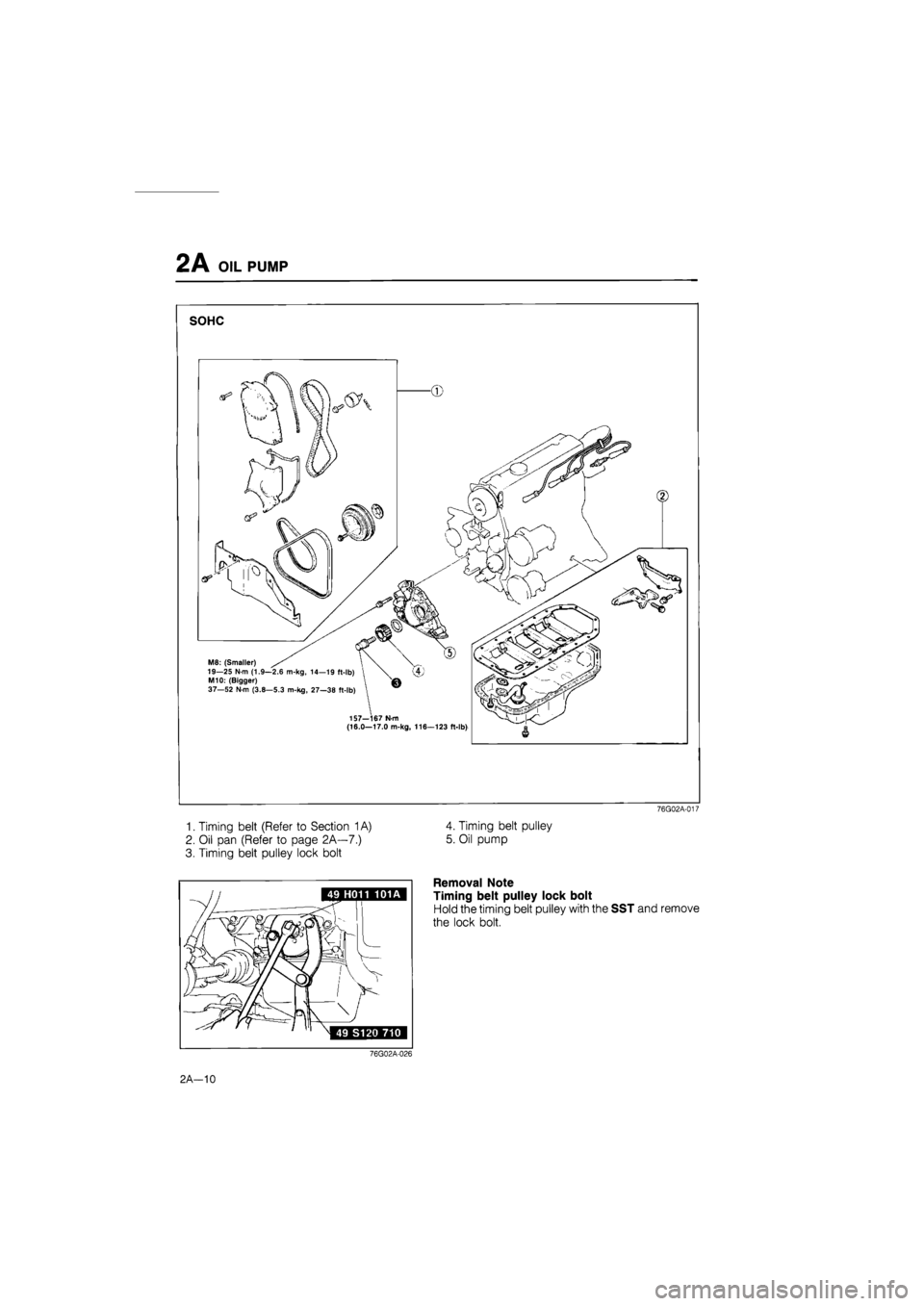
SOHC
1. Timing belt (Refer to Section
1
A)
2. Oil pan (Refer to page 2k—1)
3. Timing belt pulley lock bolt
76G02A-017
4. Timing belt pulley
5. Oil pump
Removal Note
Timing belt pulley lock bolt
Hold the timing belt pulley with the SST and remove
the lock bolt.
76G02A-026
2 A—10
Page 322 of 1865
OIL PUMP 2A
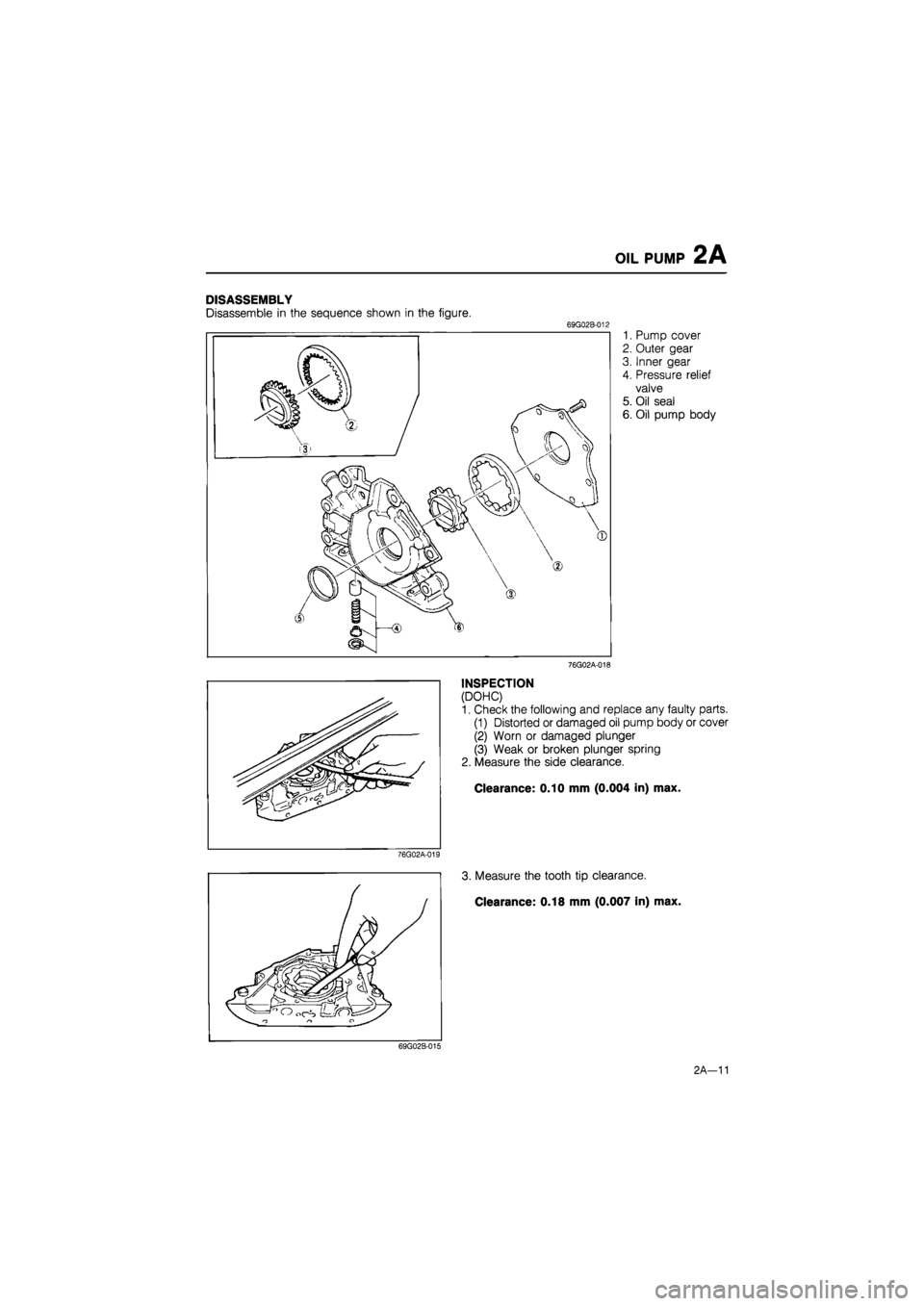
DISASSEMBLY
Disassemble in the sequence shown in the figure. 69G02B-012
1. Pump cover
2. Outer gear
3. Inner gear
4. Pressure relief
valve
5. Oil seal
6. Oil pump body
76G02A-018
INSPECTION
(DOHC)
1. Check the following and replace any faulty parts.
(1) Distorted or damaged oil pump body or cover
(2) Worn or damaged plunger
(3) Weak or broken plunger spring
2. Measure the side clearance.
Clearance: 0.10 mm (0.004 in) max.
76G02A-019
3. Measure the tooth tip clearance.
Clearance: 0.18 mm (0.007 in) max.
69G02B-015
2A-11
Page 323 of 1865
2A OIL PUMP
86U02X-021
76G02A-020
76G02A-021
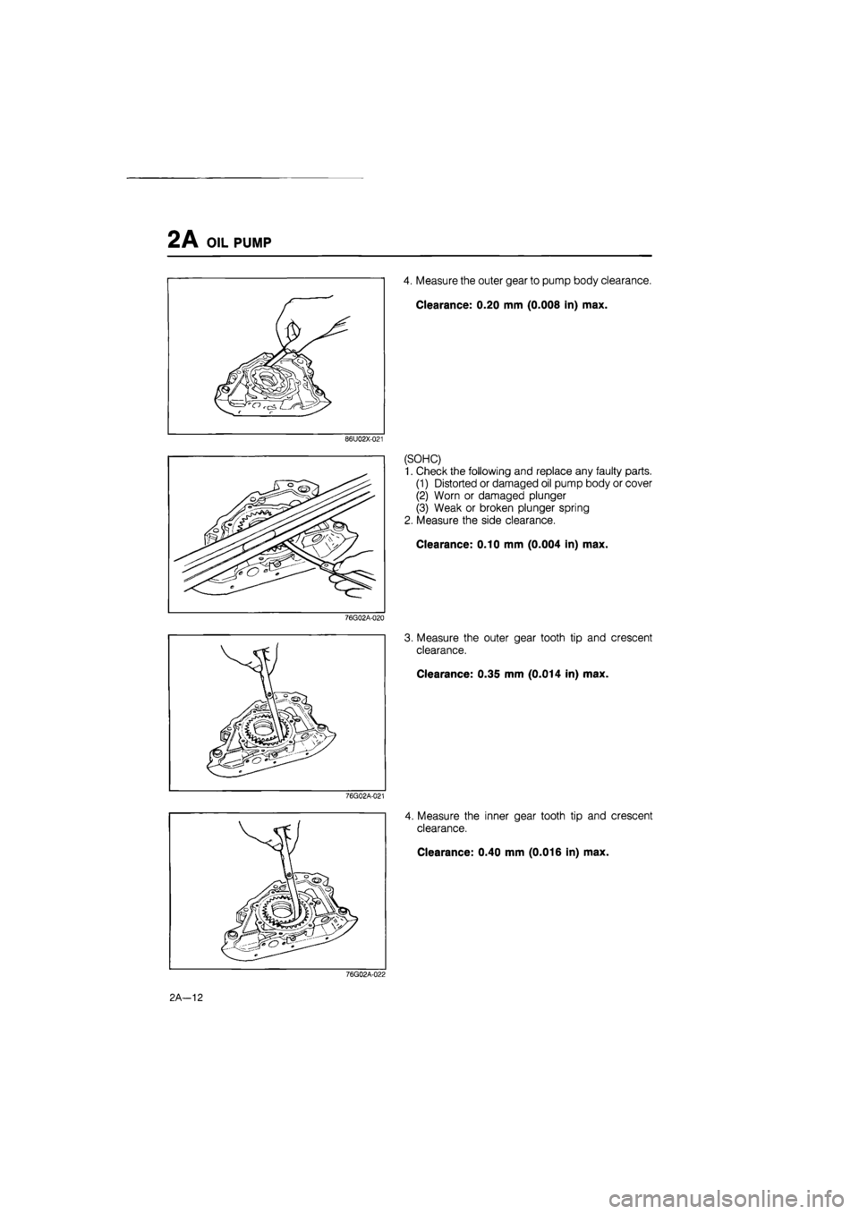
4. Measure the outer gear to pump body clearance.
Clearance: 0.20 mm (0.008 in) max.
(SOHC)
1. Check the following and replace any faulty parts.
(1) Distorted or damaged oil pump body or cover
(2) Worn or damaged plunger
(3) Weak or broken plunger spring
2. Measure the side clearance.
Clearance: 0.10 mm (0.004 in) max.
3. Measure the outer gear tooth tip and crescent
clearance.
Clearance: 0.35 mm (0.014 in) max.
4. Measure the inner gear tooth tip and crescent
clearance.
Clearance: 0.40 mm (0.016 in) max.
76G02A-022
2 A—12
Page 324 of 1865

OIL PUMP 2 A
76G02A-023
86U02X-022
76G02A-024
5. Measure the outer gear to pump body clearance.
Clearance: 0.20 mm (0.008 in) max.
ASSEMBLY
Assemble the pump as follows.
Oil Seal
1. Apply engine oil to the pump body and the out-
side of the new oil seal.
2. Press in the oil seal.
Pressure Relief Valve
1. Install the plunger and spring in the pump body.
2. Fit the snap ring.
Outer and Inner Gear
Install the gears to the pump body.
Oil Pump Cover
1. Apply thread locking compound to the cover
mounting screws' threads.
2. Attach the oil pump cover to the body.
Tightening torque:
6—9 N-m (60—90 cm-kg, 52—78 in-lb)
INSTALLATION
Install in the reverse order of removal referring to the
installation note.
Installation Note
Oil pump
1. Apply grease to a new O-ring and install it in the
oil pump body.
2. Apply silicon sealant to the shaded area as shown
in the figure.
3. Apply engine oil to the oil seal lip.
76G02A-027
2A-13
Page 325 of 1865

2B
LUBRICATION SYSTEM
(DIESEL)
OUTLINE 2B— 2
LUBRICATION CIRCUIT 2B— 2
SPECIFICATIONS 2B— 3
TROUBLESHOOTING GUIDE 2B— 4
INSPECTION 2B— 5
ENGINE OIL 2B— 5
OIL PRESSURE 2B— 5
ENGINE OIL 2B— 6
REPLACEMENT 2B— 6
OIL FILTER 2B— 6
REPLACEMENT 2B— 6
OIL COOLER AND OIL FILTER BODY 2B— 7
REMOVAL 2B— 7
INSPECTION 2B— 7
INSTALLATION 2B— 8
OIL PAN 2B— 9
REMOVAL 2B— 9
INSPECTION 2B—10
INSTALLATION 2B—10
OIL PUMP 2B—12
REMOVAL 2B—12
DISASSEMBLY 2B—13
INSPECTION 2B—13
ASSEMBLY 2B—14
INSTALLATION 2B—14
OIL JET 2B—15
REMOVAL 2B—15
INSPECTION 2B—15
INSTALLATION 2B—15
76G02B-001