MAZDA 626 1987 Workshop Manual
Manufacturer: MAZDA, Model Year: 1987, Model line: 626, Model: MAZDA 626 1987Pages: 1865, PDF Size: 94.35 MB
Page 1 of 1865
Mazda
expert22 fl/ia http://rutracker.org
787
Page 2 of 1865
Mazda
626
Workshop
Manual
FOREWORD
This workshop manual is intended for use
by service technicians of authorized Mazda
dealers to help them service Mazda vehicles.
This manual can be also useful in diagnosing
certain problems and performing some repair
and maintenance on Mazda vehicles.
For proper repair and maintenance, it is im-
portant to be thoroughly familiarized with this
manual. It is recommended that this manual al-
ways be kept in a handy place for quick and
easy reference.
All the contents of this manual, including pho-
tographs, drawings, and specifications, are the
latest available at the time of printing. As modifi-
cations affecting repair or maintenance occur,
relevant information supplementary to this
volume will be made available at Mazda deal-
ers. This manual should be kept up-to-date.
Mazda Motor Corporation reserves the right
to alter the specifications and contents of this
manual without obligation or advance notice.
All rights reserved. No part of this book may
be reproduced or utilized in any form or by any
means, electronic or mechanical, including
photocopying, recording, or by any informa-
tion storage and retrieval system, without per-
mission in writing.
Mazda Motor Corporation
HIROSHIMA JAPAN
Refer to the following wiring diagrams if
necessary.
Refer to From No.
5095-10-87 G L.H.D.
5096-10-87 G R.H.D.
5096-20-871 Germany
5095-30-871 French
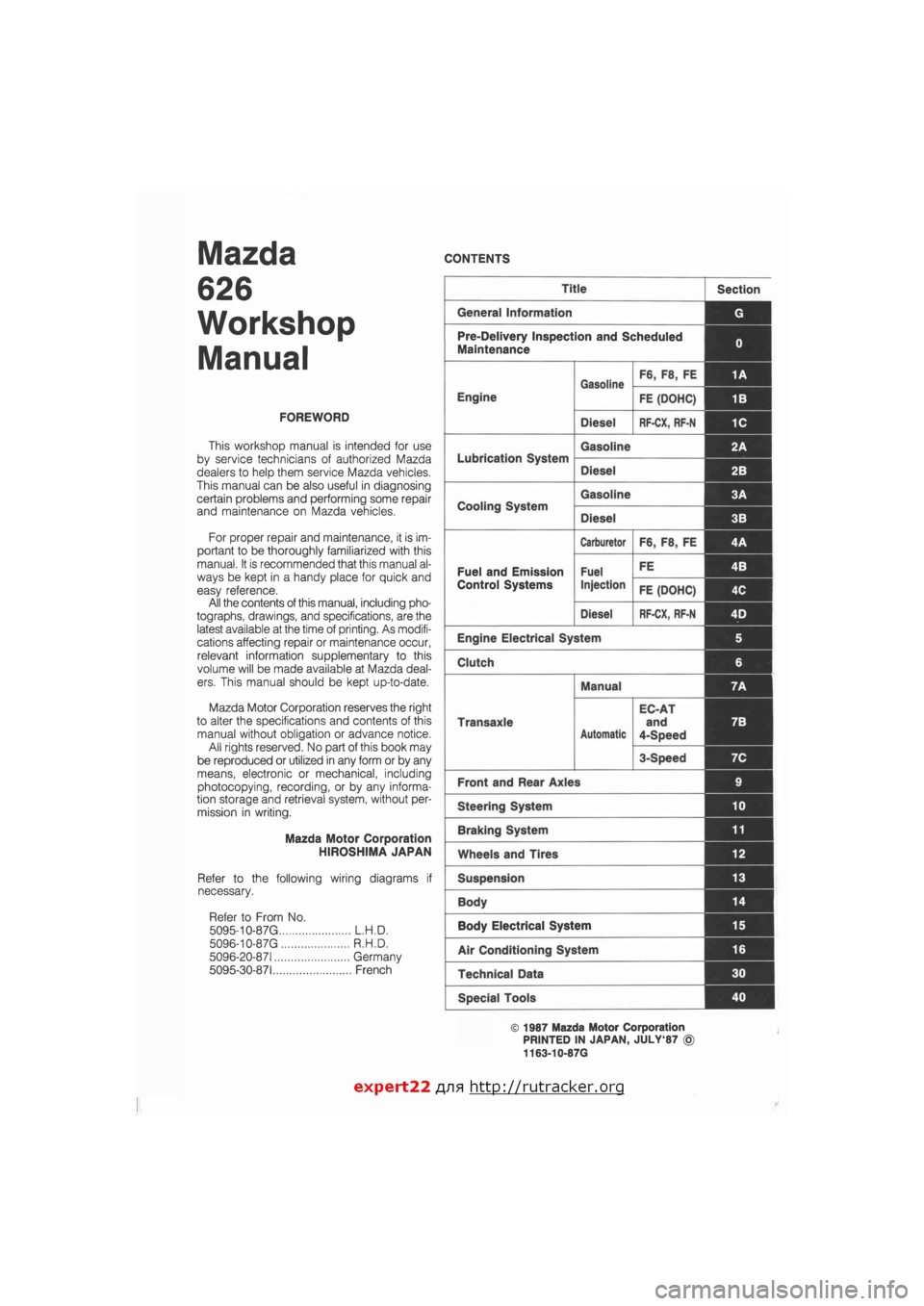
CONTENTS
Title Section
General Information G
Pre-Delivery Inspection and Scheduled
Maintenance 0
Gasoline F6, F8, FE 1A
Engine
Gasoline
FE (DOHC) 1B
Diesel RF-CX, RF-N 1C
Lubrication System
Gasoline 2A
Lubrication System
Diesel 2B I
Cooling System
Gasoline 3A 1
Cooling System
Diesel 3B
Carburetor F6, F8, FE 4A
Fuel and Emission Fuel FE 4B I
Control Systems Injection FE (DOHC) 4C
Diesel RF-CX, RF-N 4D j
Engine Electrical System 5
Clutch 6
Manual 7A
Transaxle
Automatic
EC-AT
and
4-Speed
7B
3-Speed 7C
Front and Rear Axles 9
Steering System 10
Braking System 11
Wheels and Tires 12
Suspension 13
Body 14 |
Body Electrical System 15
Air Conditioning System 16
Technical Data 30
Special Tools 40
© 1987 Mazda Motor Corporation
PRINTED IN JAPAN, JULY'87 ©
1163-10-87G
expert22 flna http://rutracker.org
Page 3 of 1865
GENERAL INFORMATION
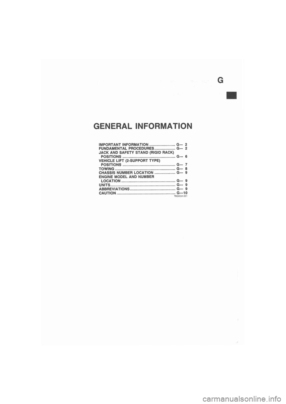
IMPORTANT INFORMATION G— 2
FUNDAMENTAL PROCEDURES G— 2
JACK AND SAFETY STAND (RIGID RACK)
POSITIONS G— 6
VEHICLE LIFT (2-SUPPORT TYPE)
POSITIONS G- 7
TOWING G— 8
CHASSIS NUMBER LOCATION G— 9
ENGINE MODEL AND NUMBER
LOCATION G— 9
UNITS G— 9
ABBREVIATIONS G— 9
CAUTION G—10 76G0GX-001
Page 4 of 1865
G IMPORTANT INFORMATION/FUNDAMENTAL PROCEDURES
IMPORTANT INFORMATION
BASIC ASSUMPTIONS
This workshop manual assumes that you have arid know how to properly use certain special tools
which are necessary for the safe and efficient performance of service operations on Mazda vehicles.
The manual also assumes that you are familiar generally with automobile systems and basic service
and repair procedures. You should not attempt to use this manual unless these assumptions are cor-
rect and you understand the consequences described below.
SAFETY RISK
This manual contains certain notes, warnings, etc., which you should carefully read and follow in or-
der to eliminate the risk of personal injury to yourself or others and the risk of improper service which
may damage the vehicle or render it unsafe. The fact that there are no such notes, etc., with respect
to any specific service method does not mean that there is no possibility that personal safety or vehicle
safety will be jeopardized by the use of incorrect methods or tools.
POSSIBLE LOSS OF WARRANTY
The manufacturer's warranty on Mazda vehicles and engines can be voided if improper service or
repairs are performed by persons other than an authorized Mazda dealer.
FUNDAMENTAL PROCEDURES
As you read through the procedure, you will come
across NOTES, CAUTIONS, and WARNINGS. Each
one is there for a specific purpose. NOTES give you
added information that will help you to complete a
particular procedure. CAUTIONS are given to pre-
vent you from making an error that could damage
the vehicle. WARNINGS remind you to be espe-
cially careful in those areas where carelessness can
cause personal injury. The following list contains
some general WARNINGS that you should follow
when you work on a vehicle.
PROTECTION OF THE VEHICLE
Always be sure to cover fenders, seats, and floor
areas before starting work.
A WORD ABOUT SAFETY
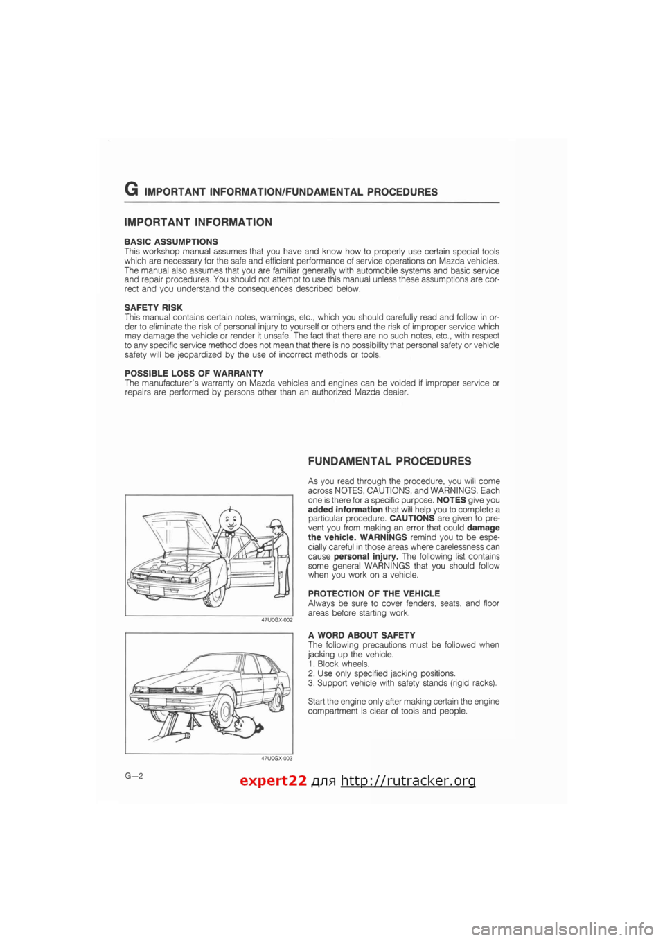
The following precautions must be followed when
jacking up the vehicle.
1. Block wheels.
2. Use only specified jacking positions.
3. Support vehicle with safety stands (rigid racks).
Start the engine only after making certain the engine
compartment is clear of tools and people.
G—2 expert22 fl/i* http://rutracker.org
Page 5 of 1865
FUNDAMENTAL PROCEDURES G
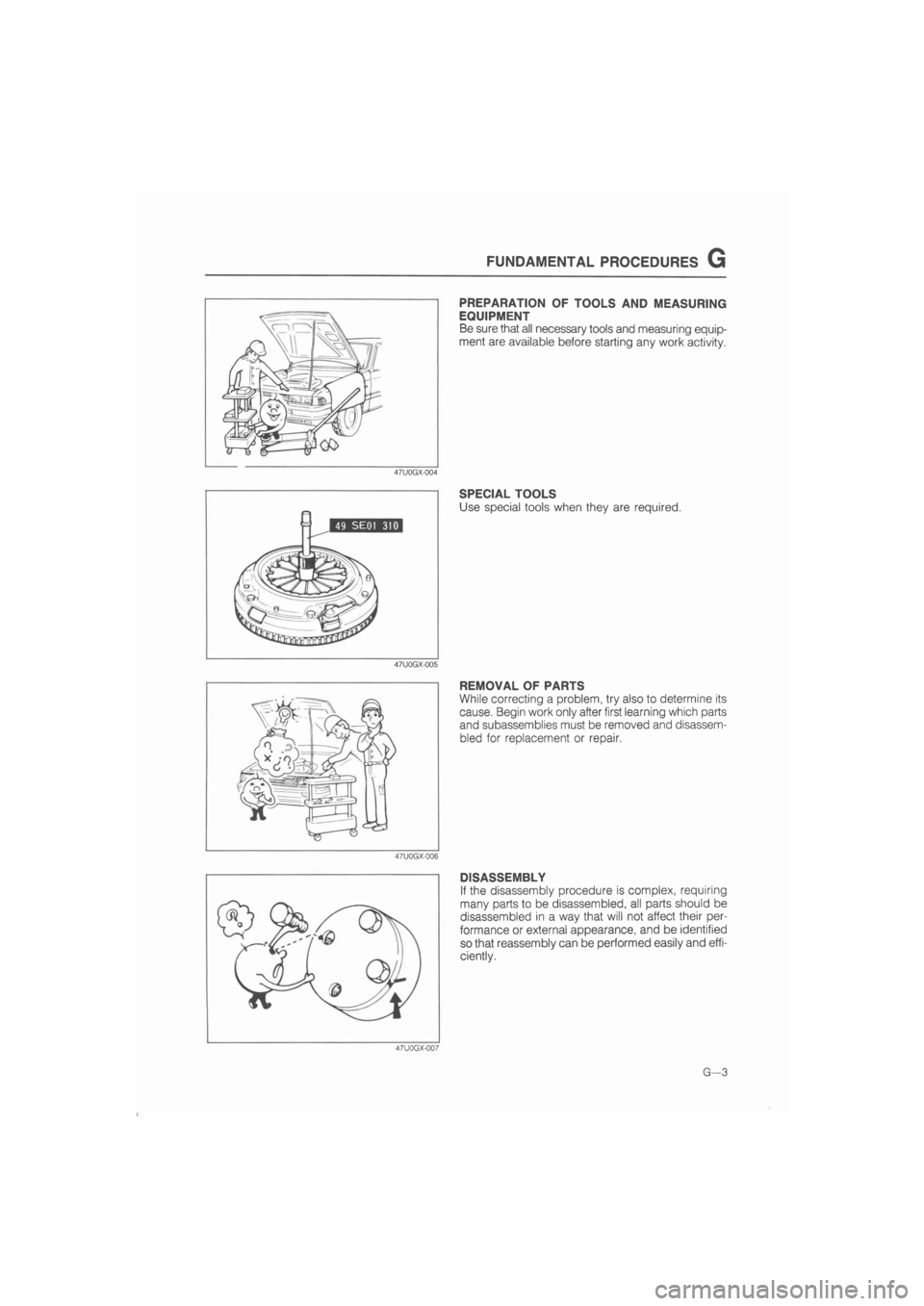
PREPARATION OF TOOLS AND MEASURING
EQUIPMENT
Be sure that all necessary tools and measuring equip-
ment are available before starting any work activity.
47U0GX-004
SPECIAL TOOLS
Use special tools when they are required.
47U0GX-005
REMOVAL OF PARTS
While correcting a problem, try also to determine its
cause. Begin work only after first learning which parts
and subassemblies must be removed and disassem-
bled for replacement or repair.
47U0GX-006
DISASSEMBLY
If the disassembly procedure is complex, requiring
many parts to be disassembled, all parts should be
disassembled in a way that will not affect their per-
formance or external appearance, and be identified
so that reassembly can be performed easily and effi-
ciently.
47U0GX-007
G—3
l
Page 6 of 1865
G FUNDAMENTAL PROCEDURES
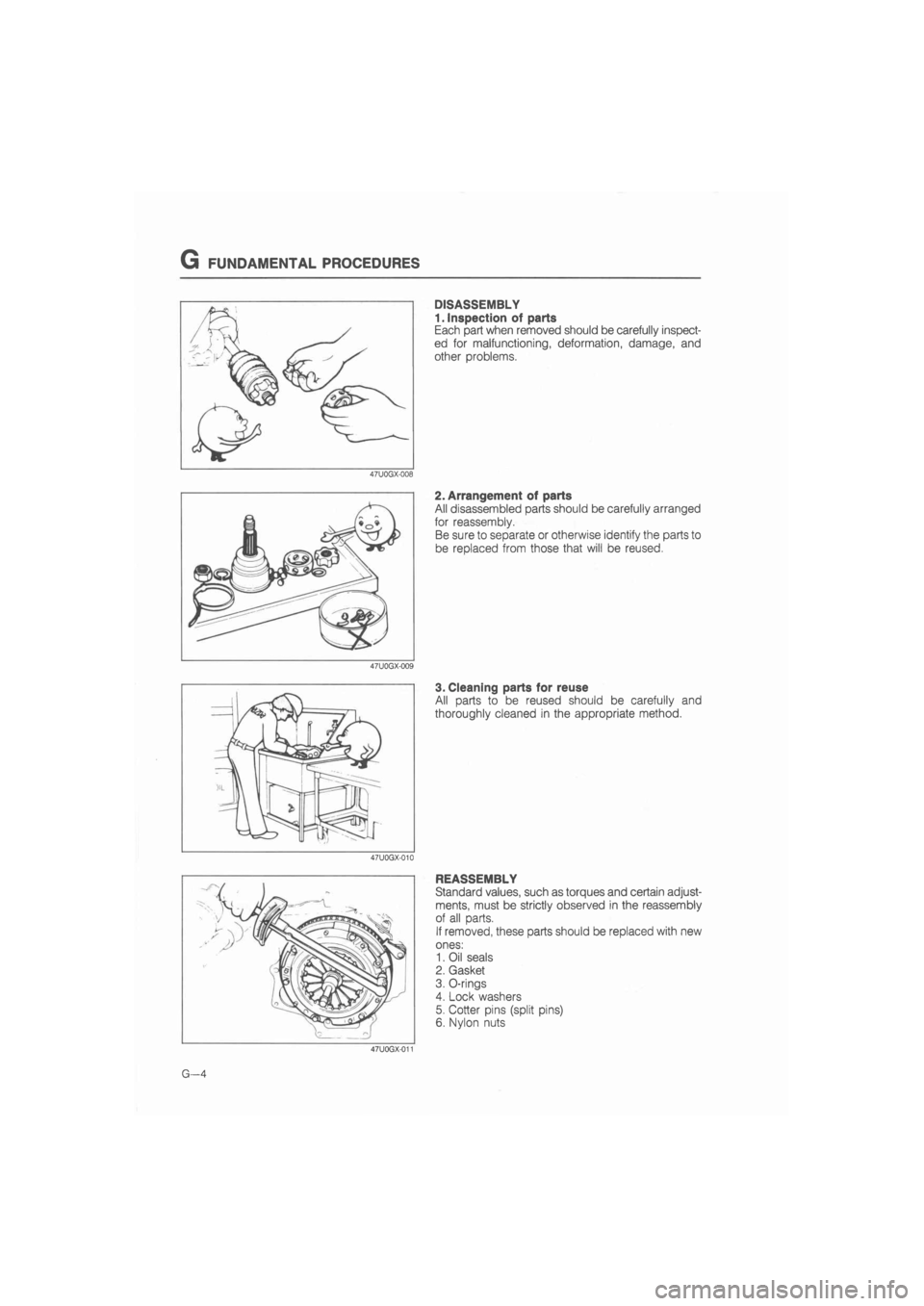
DISASSEMBLY
1. Inspection of parts
Each part when removed should be carefully inspect-
ed for malfunctioning, deformation, damage, and
other problems.
2. Arrangement of parts
All disassembled parts should be carefully arranged
for reassembly.
Be sure to separate or otherwise identify the parts to
be replaced from those that will be reused.
3. Cleaning parts for reuse
All parts to be reused should be carefully and
thoroughly cleaned in the appropriate method.
REASSEMBLY
Standard values, such as torques and certain adjust-
ments, must be strictly observed in the reassembly
of all parts.
If removed, these parts should be replaced with new
ones:
1. Oil seals
2. Gasket
3. O-rings
4. Lock washers
5. Cotter pins (split pins)
6. Nylon nuts
G—4
Page 7 of 1865
FUNDAMENTAL PROCEDURES G
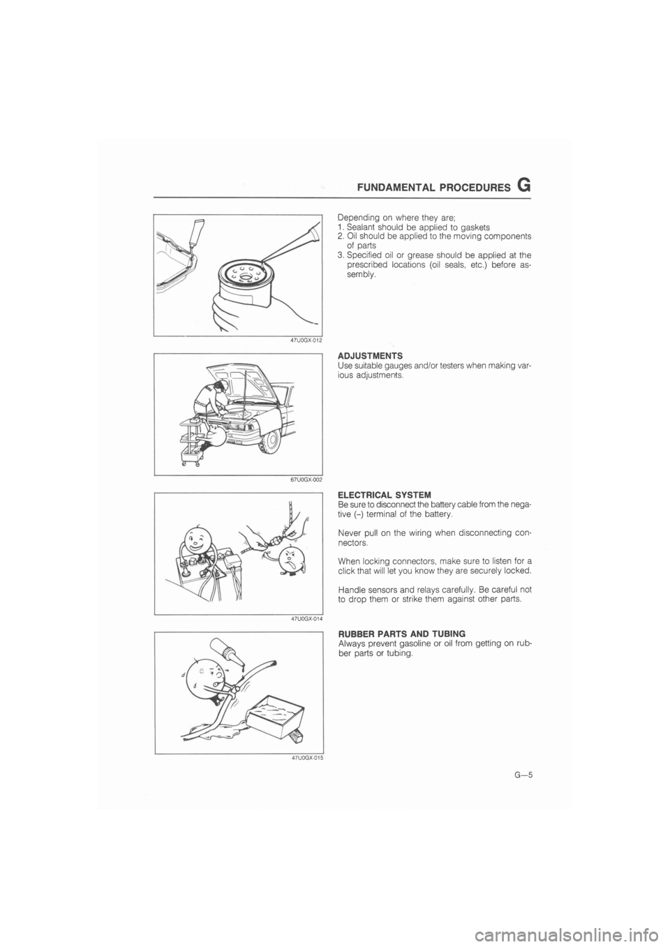
Depending on where they are;
1. Sealant should be applied to gaskets
2. Oil should be applied to the moving components
of parts
3. Specified oil or grease should be applied at the
prescribed locations (oil seals, etc.) before as-
sembly.
47U0GX-012
ADJUSTMENTS
Use suitable gauges and/or testers when making var-
ious adjustments.
67U0GX-002
ELECTRICAL SYSTEM
Be sure to disconnect the battery cable from the nega-
tive (-) terminal of the battery.
Never pull on the wiring when disconnecting con-
nectors.
When locking connectors, make sure to listen for a
click that will let you know they are securely locked.
Handle sensors and relays carefully. Be careful not
to drop them or strike them against other parts.
47U0GX-014
RUBBER PARTS AND TUBING
Always prevent gasoline or oil from getting on rub-
ber parts or tubing.
47U0GX-015
G—5
Page 8 of 1865
G
JACK AND
SAFETY STAND
(RIGID RACK)
POSITIONS
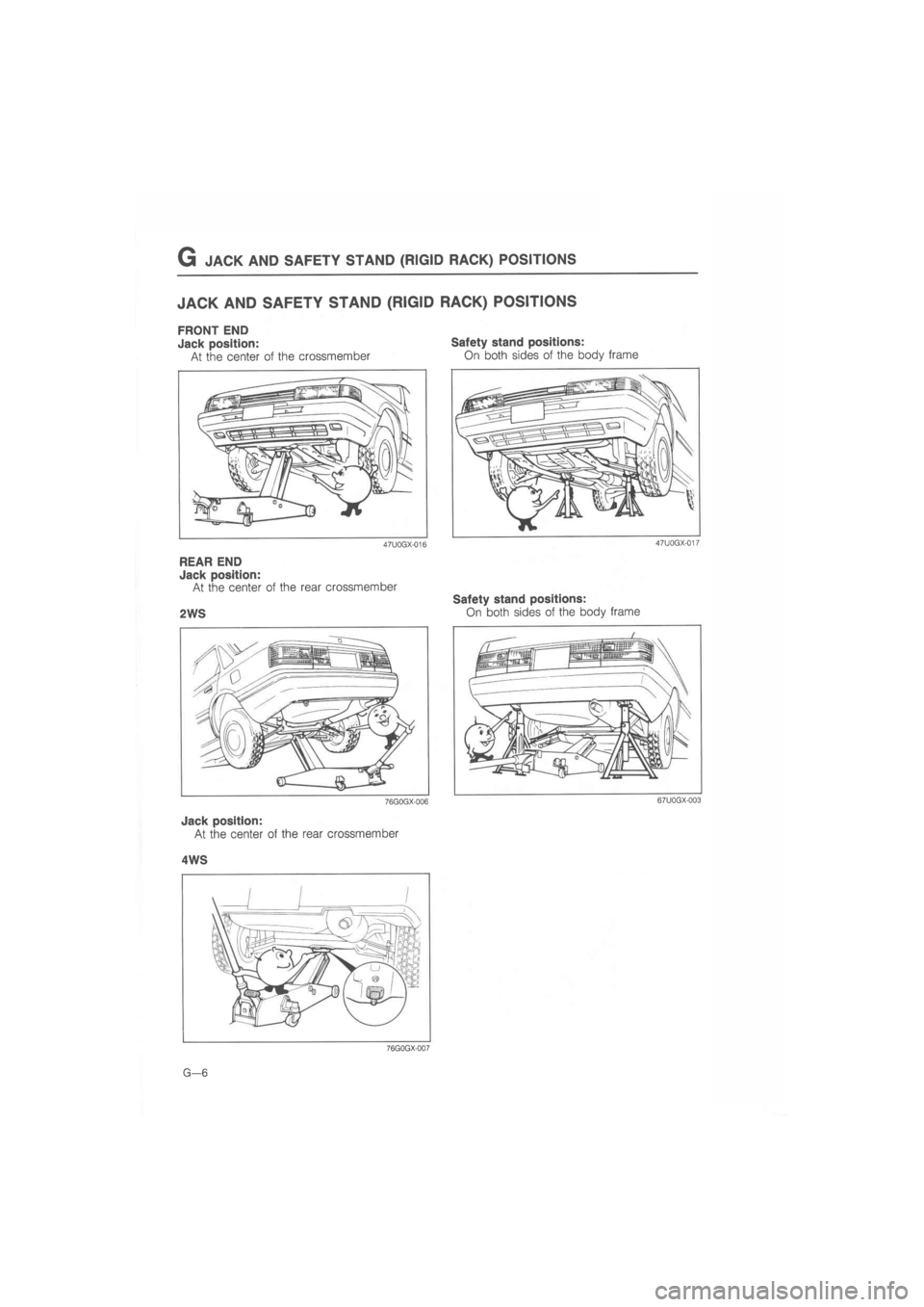
JACK AND SAFETY STAND
(RIGID RACK)
POSITIONS
FRONT END
Jack position:
At the center of the crossmember
Safety stand positions:
On both sides of the body frame
47U0GX-017 47U0GX-016
REAR END
Jack position:
At the center of the rear crossmember
2WS
76G0GX-006
Jack position:
At the center of the rear crossmember
Safety stand positions:
On both sides of the body frame
4WS
76G0GX-007
G—6
Page 9 of 1865
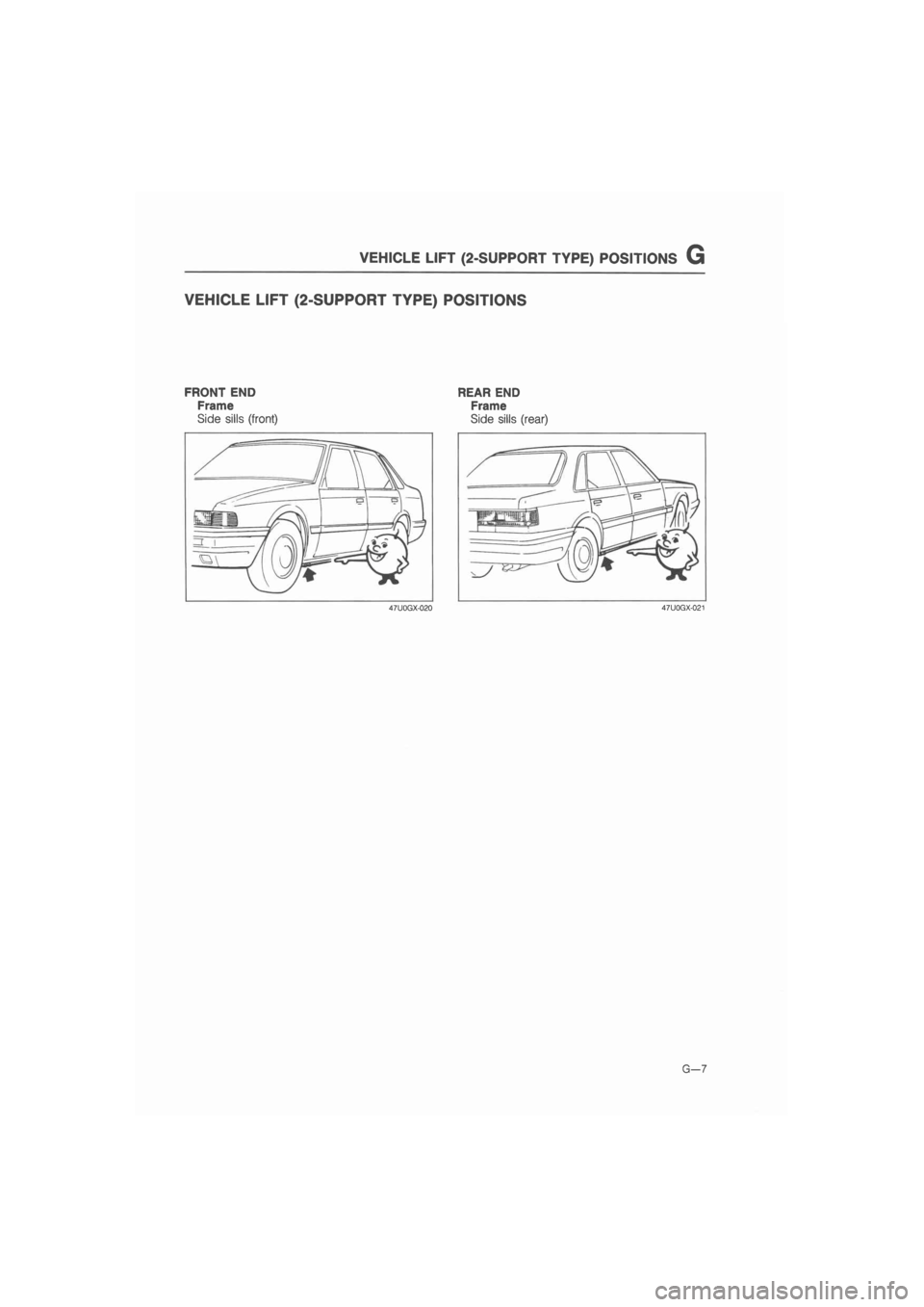
VEHICLE LIFT (2-SUPPORT TYPE)
POSITIONS G
VEHICLE
LIFT
(2-SUPPORT
TYPE)
POSITIONS
FRONT END
Frame
Side sills (front)
REAR END
Frame
Side sills (rear)
47U0GX-020 47U0GX-021
G—7
Page 10 of 1865
G TOWING
76GOGX-OQ2
i-^C.
y -
- r^jfftj&H
r —I
76UQGX-003
86U0GX-004
G—8
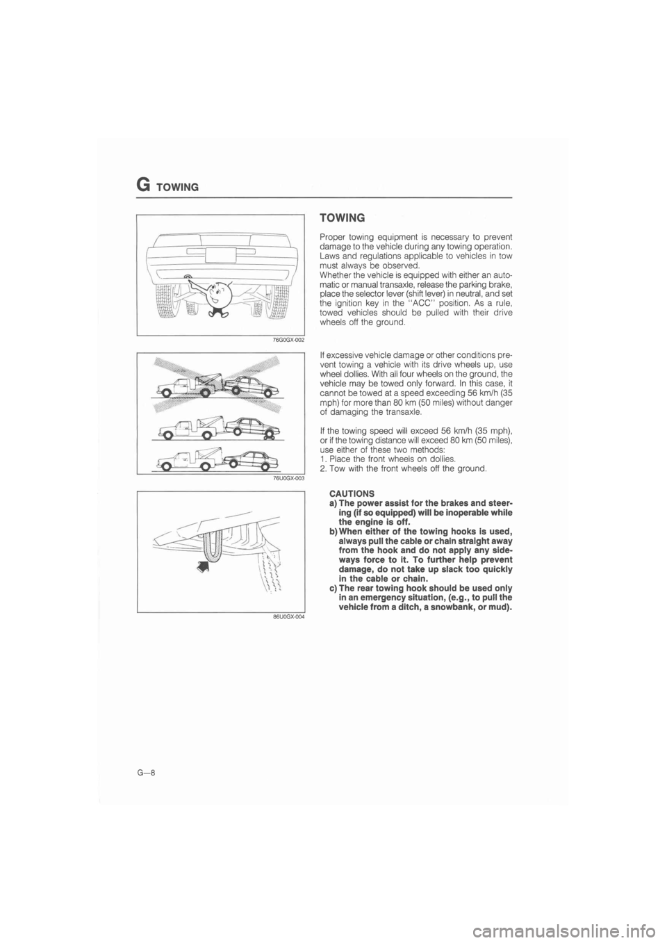
TOWING
Proper towing equipment is necessary to prevent
damage to the vehicle during any towing operation.
Laws and regulations applicable to vehicles in tow
must always be observed.
Whether the vehicle is equipped with either an auto-
matic or manual transaxle, release the parking brake,
place the selector lever (shift lever) in neutral, and set
the ignition key in the "ACC" position. As a rule,
towed vehicles should be pulled with their drive
wheels off the ground.
If excessive vehicle damage or other conditions pre-
vent towing a vehicle with its drive wheels up, use
wheel dollies. With all four wheels on the ground, the
vehicle may be towed only forward. In this case, it
cannot be towed at a speed exceeding 56 km/h (35
mph) for more than 80 km (50 miles) without danger
of damaging the transaxle.
If the towing speed will exceed 56 km/h (35 mph),
or if the towing distance will exceed 80 km (50 miles),
use either of these two methods:
1. Place the front wheels on dollies.
2. Tow with the front wheels off the ground.
CAUTIONS
a) The power assist for the brakes and steer-
ing (if so equipped) will be inoperable while
the engine is off.
b)When either of the towing hooks is used,
always pull the cable or chain straight away
from the hook and do not apply any side-
ways force to it. To further help prevent
damage, do not take up slack too quickly
in the cable or chain.
c) The rear towing hook should be used only
in an emergency situation, (e.g., to pull the
vehicle from a ditch, a snowbank, or mud).