jump start MAZDA 626 1987 Workshop Manual
[x] Cancel search | Manufacturer: MAZDA, Model Year: 1987, Model line: 626, Model: MAZDA 626 1987Pages: 1865, PDF Size: 94.35 MB
Page 473 of 1865
TROUBLESHOOTING WITH SST 4B
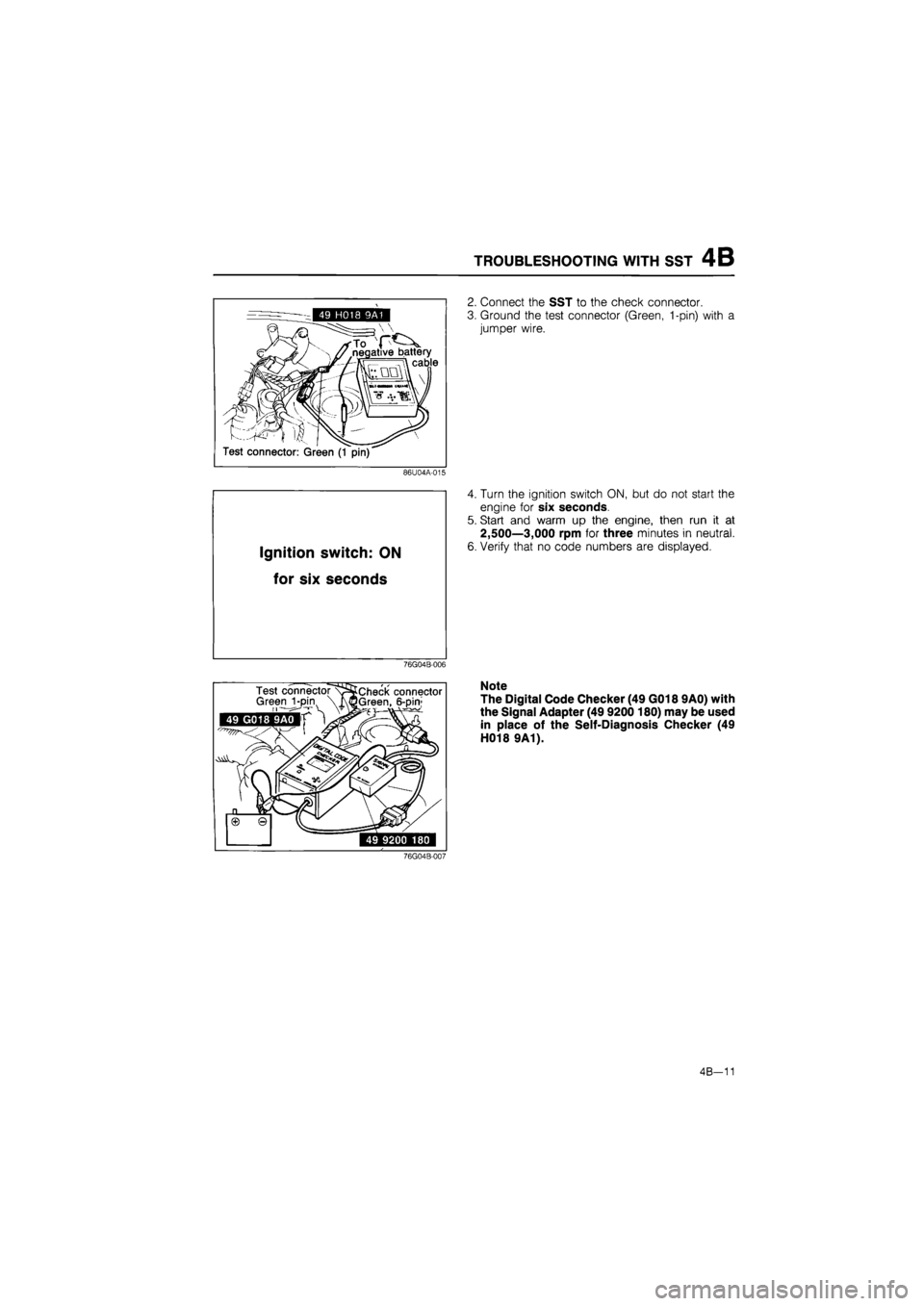
2. Connect the SST to the check connector.
3. Ground the test connector (Green, 1-pin) with a
jumper wire.
86U04A-015
Ignition switch:
ON
for six
seconds
4. Turn the ignition switch ON, but do not start the
engine for six seconds.
5. Start and warm up the engine, then run it at
2,500—3,000 rpm for three minutes in neutral.
6. Verify that no code numbers are displayed.
76G04B-006
76G04B-007
Note
The Digital Code Checker (49 G018 9A0) with
the Signal Adapter (49 9200 180) may be used
in place of the Self-Diagnosis Checker (49
H018 9A1).
4B-11
Page 488 of 1865
4B SWITCH MONITOR FUNCTION
49 H018 9A1
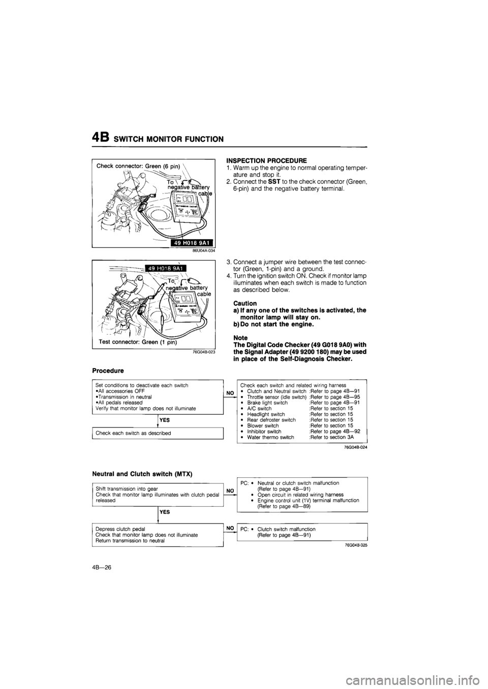
INSPECTION PROCEDURE
1. Warm up the engine to normal operating temper-
ature and stop it.
2. Connect the SST to the check connector (Green,
6-pin) and the negative battery terminal.
86U04A-034
76G04B-023
3. Connect a jumper wire between the test connec-
tor (Green, 1-pin) and a ground.
4. Turn the ignition switch ON. Check if monitor lamp
illuminates when each switch is made to function
as described below.
Caution
a) If any one of the switches is activated, the
monitor lamp will stay on.
b) Do not start the engine.
Note
The Digital Code Checker (49 G018 9A0) with
the Signal Adapter (49 9200180) may be used
in place of the Self-Diagnosis Checker.
Procedure
76G04B-024
4B—26
Page 511 of 1865
FUEL SYSTEM 4B
76G04B-126
86U04A-078
V^AN.
- Test connector
(Yellow)
76G04B-063
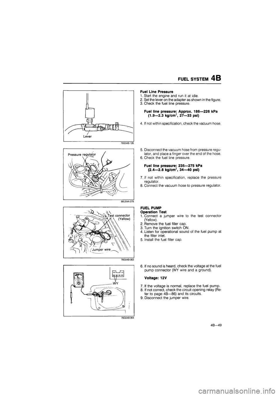
Fuel Line Pressure
1. Start the engine and run it at idle.
2. Set the lever on the adapter as shown in the figure.
3. Check the fuel line pressure.
Fuel line pressure: Approx. 186—226 kPa
(1.9—2.3 kg/cm2, 27—33 psi)
4. If not within specification, check the vacuum hose.
5. Disconnect the vacuum hose from pressure regu-
lator, and place a finger over the end of the hose.
6. Check the fuel line pressure.
Fuel line pressure: 235—275 kPa
(2.4—2.8 kg/cm2, 34—40 psi)
7. If not within specification, replace the pressure
regulator.
8. Connect the vacuum hose to pressure regulator.
FUEL PUMP
Operation Test
1. Connect a jumper wire to the test connector
(Yellow).
2. Remove the fuel filler cap.
3. Turn the ignition switch ON.
4. Listen for operational sound of the fuel pump at
the filler inlet.
5. Install the fuel filler cap.
6. If no sound is heard, check the voltage at the fuel
pump connector (WY wire and a ground).
Voltage: 12V
7. If the voltage is normal, replace the fuel pump.
8. If not correct, check the circuit opening relay (Re-
fer to page 4B—86) and its circuits.
9. Disconnect the jumper wire.
76G04B-064
4B—49
Page 574 of 1865
TROUBLESHOOTING WITH SST 4C
49 H018 9A1
negative battery cable
^ll
Test connector: (Green, 1 pin)
86U04A-015
Ignition switch:
ON
for six
seconds
76G04C-014
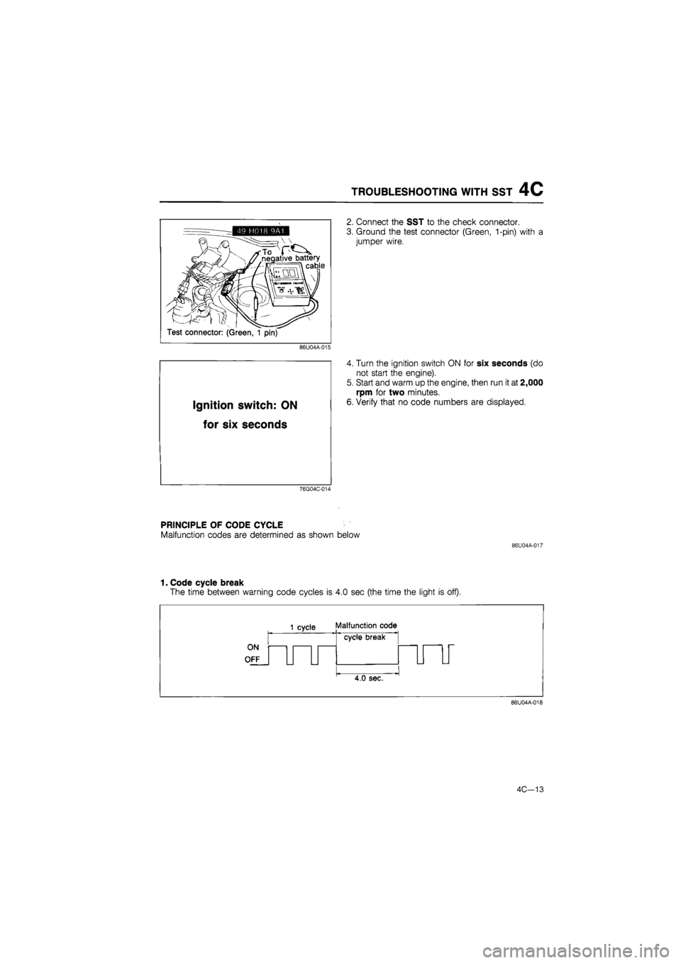
2. Connect the SST to the check connector.
3. Ground the test connector (Green, 1-pin) with a
jumper wire.
4. Turn the ignition switch ON for six seconds (do
not start the engine).
5. Start and warm up the engine, then run it at 2,000
rpm for two minutes.
6. Verify that no code numbers are displayed.
PRINCIPLE OF CODE CYCLE
Malfunction codes are determined as shown below
86U04A-017
1. Code cycle break
The time between warning code cycles is 4.0 sec (the time the light is off).
ON
OFF
1 cycle Malfunction code
cycle break
4.0 sec.
86U04A-018
4C—13
Page 587 of 1865
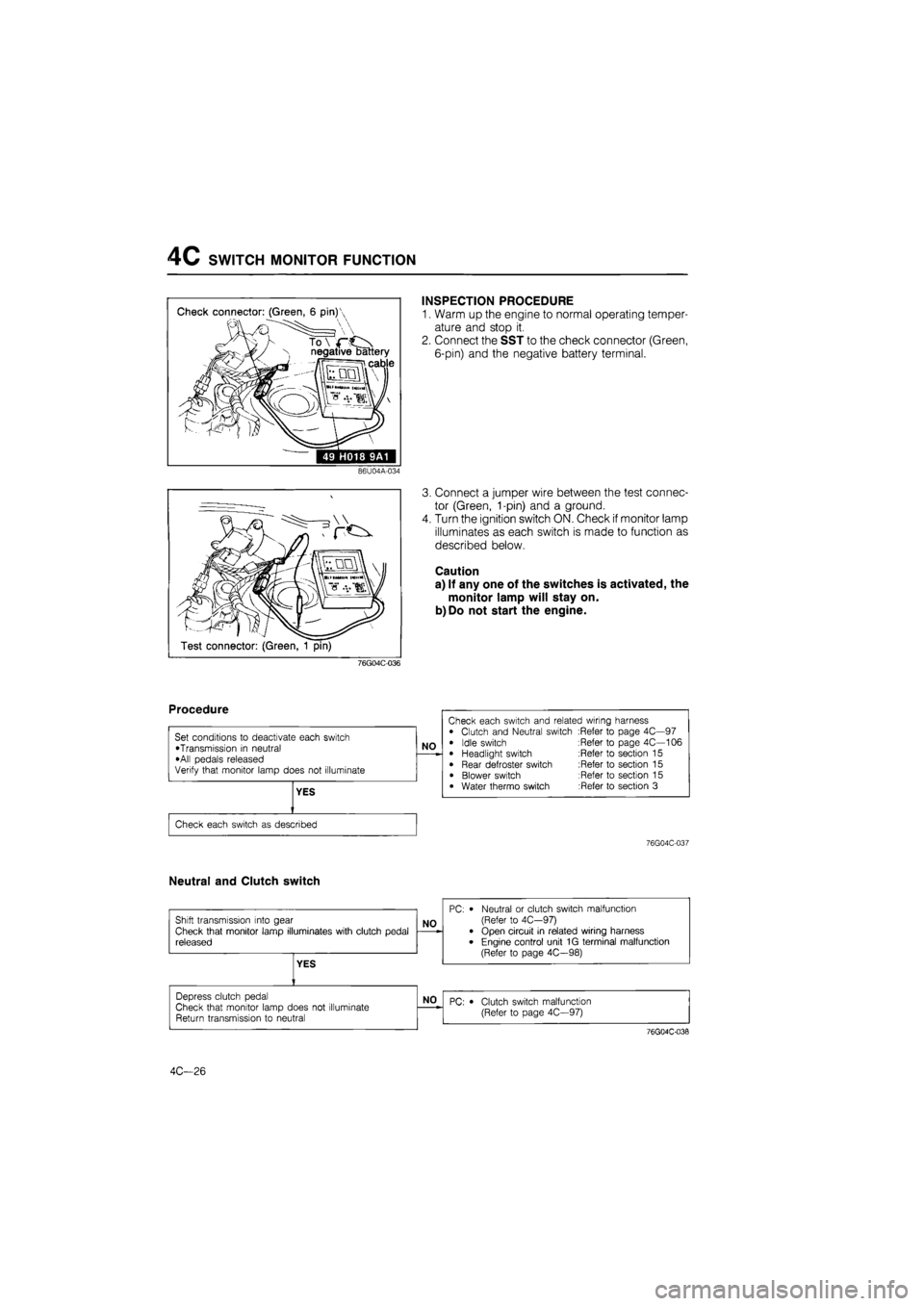
4C SWITCH MONITOR FUNCTION
Check connector: (Green, 6 pin)'
N negative battery
ii cable
49 H018 9A1
INSPECTION PROCEDURE
1. Warm up the engine to normal operating temper-
ature and stop it.
2. Connect the SST to the check connector (Green,
6-pin) and the negative battery terminal.
86U04A-034
Test connector: (Green, 1 pin)
3. Connect a jumper wire between the test connec-
tor (Green, 1-pin) and a ground.
4. Turn the ignition switch ON. Check if monitor lamp
illuminates as each switch is made to function as
described below.
Caution
a) If any one of the switches is activated, the
monitor lamp will stay on.
b)Do not start the engine.
76G04C-036
76G04C-037
Neutral and Clutch switch
4C—26
Page 616 of 1865
FUEL SYSTEM 4C
i i 1 1 1 i i
r.:.:::r t t t t t izn —i—i—i—i—i—i—i—i—
2DD 350
86U04A-074
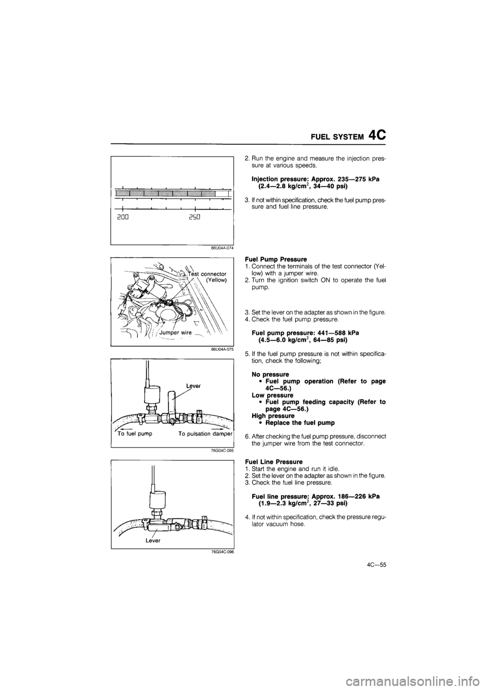
2. Run the engine and measure the injection pres-
sure at various speeds.
Injection pressure: Approx. 235—275 kPa
(2.4—2.8 kg/cm2, 34—40 psi)
3. If not within specification, check the fuel pump pres-
sure and fuel line pressure.
Fuel Pump Pressure
1. Connect the terminals of the test connector (Yel-
low) with a jumper wire.
2. Turn the ignition switch ON to operate the fuel
pump.
3. Set the lever on the adapter as shown in the figure.
4. Check the fuel pump pressure.
Fuel pump pressure: 441—588 kPa
(4.5—6.0 kg/cm2, 64—85 psi)
5. If the fuel pump pressure is not within specifica-
tion, check the following;
No pressure
• Fuel pump operation (Refer to page
4C—56.)
Low pressure
• Fuel pump feeding capacity (Refer to
page 4C—56.)
High pressure
• Replace the fuel pump
6. After checking the fuel pump pressure, disconnect
the jumper wire from the test connector.
Fuel Line Pressure
1. Start the engine and run it idle.
2. Set the lever on the adapter as shown in the figure.
3. Check the fuel line pressure.
Fuel line pressure: Approx. 186—226 kPa
(1.9—2.3 kg/cm2, 27—33 psi)
4. If not within specification, check the pressure regu-
lator vacuum hose.
4C-55
Page 1468 of 1865
1 1 ANTI-LOCK BRAKE SYSTEM (ABS)
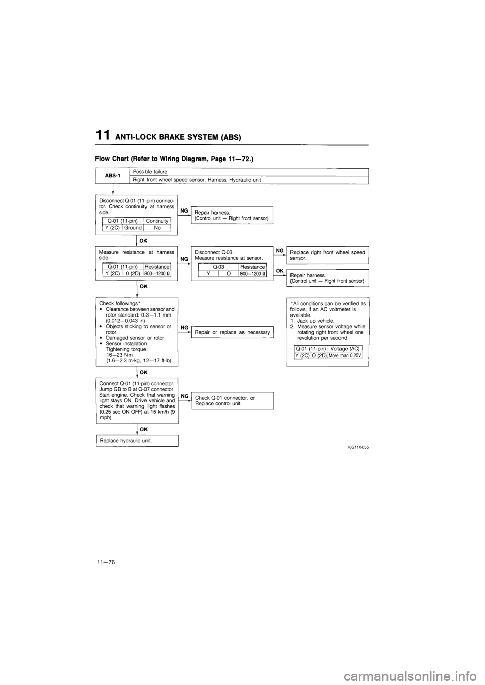
Flow Chart (Refer to Wiring Diagram, Page 11—72.)
ABS-1
Possible failure
Right front wheel speed sensor, Harness, Hydraulic unit
Disconnect Q-01 (11-pin) connec-tor. Check continuity
at
harness side.
Q-01 (11-pin)
I
Continuity
Y (2C) Ground No
OK
Measure resistance
at
harness side.
Q-01 (11-pin) Resistance
Y (2C)
i 0
(2D) 800—1200
Q
OK
NG
Repair harness.
(Control unit — Right front sensor)
NG
Disconnect Q-03. Measure resistance
at
sensor.
Q-03 Resistance
Y
[ O
800—1200 Q
NG
Replace right front wheel speed sensor.
OK
Repair harness.
(Control unit — Right front sensor)
Check followings*
• Clearance between sensor and rotor standard: 0.3—1.1
mm
(0.012-0.043
in)
• Objects sticking
to
sensor
or
rotor
• Damaged sensor
or
rotor
• Sensor installation Tightening torque: 16-23 N-m (1.6-2.3 m-kg, 12—17 ft-lb)
OK
Connect Q-01 (11-pin) connector. Jump GB
to B at
Q-07 connector. Start engine. Check that warning light stays ON. Drive vehicle and check that warning light flashes (0.25 sec ON OFF)
at 15
km/h
(9
mph).
NG
Repair
or
replace
as
necessary
* All conditions can
be
verified
as
follows,
if an AC
voltmeter
is
available. 1. Jack
up
vehicle. 2. Measure sensor voltage while rotating right front wheel
one
revolution
per
second.
Q-01 (11-Din) Voltage (AC)
Y (2C) O (2D) More than 0.25V
NG
Check Q-01 connector,
or
Replace control unit.
OK
Replace hydraulic unit.
76G11X-055
11—76
Page 1469 of 1865
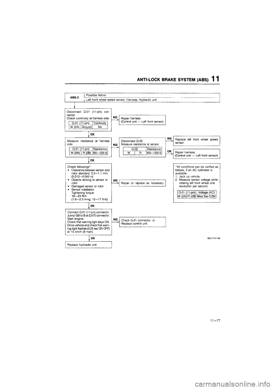
ANTI-LOCK BRAKE SYSTEM (ABS) 1 1
ABS-2
Possible failure
Left front wheel speed sensor, Harness, Hydraulic unit
Disconnect
Q-01
(11-pin)
con-
nector.
Check continuity
at
harness side.
Q-01 (11-pin) Continuity
W (2A) Ground No
OK
Measure side.
Q-01 (11-pin) Resistance
W (2A) R (2B) 800-1200
fl
OK
Connect Q-01 (11-pin) connector. Jump GB
to B
at (Q-07) connector. Start engine.
Check that warning light stays ON. Drive vehicle and check that warn-ing light flashes (0.25 sec ON OFF) at
15
km/h
(9
mph).
NG
Repair harness (Control unit
—
Left front sensor)
resistance
at
harness
NG
Disconnect Q-02 Measure resistance
at
sensor.
Q-02 Resistance
W
| R
800-1200
0
OK
Check followings*
• Clearance between sensor and rotor standard: 0.3—1.1
mm
(0.012-0.043
in)
• Objects sticking
to
sensor
or
rotor • Damaged sensor
or
rotor
• Sensor installation Tightening torque: 16-23 N m
(1.6—2.3 m-kg, 12-17 ft-lb)
NG
OK
NG
Repair
or
replace
as
necessary
NG
Check Q-01 connector,
or
Replace control unit.
OK
Replace hydraulic unit.
Replace left front wheel speed
sensor.
Repair harness.
(Control unit
—
Left front sensor)
"All conditions can
be
verified
as
follows,
if an AC
voltmeter
is
available. 1. Jack
up
vehicle. 2. Measure sensor voltage while rotating left front wheel
one
revolution
per
second.
Q-01 (11-pin) Voltage (AC)
W (2 A)
|
R (2B) More than
0
25V
86U11X-146
11-77
Page 1470 of 1865
1 1 ANTI-LOCK BRAKE SYSTEM (ABS)
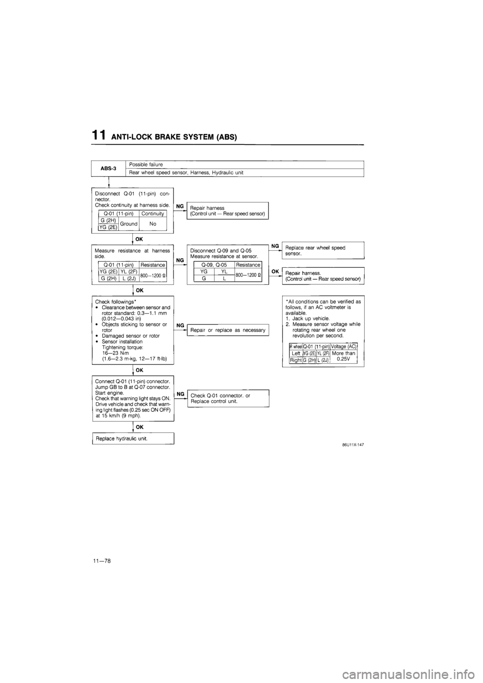
ABS-3
Possible failure
Rear wheel speed sensor, Harness, Hydraulic unit
Disconnect
Q-01
(11-pin)
con-
nector.
Check continuity
at
harness side.
Q-01 (11-pin) Continuity
G (2H) Ground No YG (2E) Ground No
Measure side.
Q-01 (11-pin) Resistance
YG (2E) YL (2F) 800—1200
fi
G (2H)
] L
(2J) 800—1200
fi
OK
Connect Q-01 (11-pin) connector. Jump GB
to B at
Q-07 connector. Start engine.
Check that warning light stays ON. Drive vehicle and check that warn-ing light flashes (0.25 sec ON OFF) at
15
km/h
(9
mph).
NG
Repair harness (Control unit
—
Rear speed sensor)
OK
resistance
at
harness
NG
Disconnect Q-09 and Q-05 Measure resistance
at
sensor.
Q-09, Q-05 Resistance
YG YL 800-1200
0
G L 800-1200
0
OK
Check followings* • Clearance between sensor and rotor standard: 0.3—1.1
mm
(0.012-0.043
in)
• Objects sticking
to
sensor
or
rotor
• Damaged sensor
or
rotor
• Sensor installation Tightening torque: 16-23 N-m
(1.6—2.3 m-kg, 12—17 ft-lb)
NG
Repair
or
replace
as
necessary
NG
Check Q-01 connector. Replace control unit.
or
OK
Replace hydraulic unit,
Replace rear wheel speed
sensor.
OK
Repair harness.
(Control unit
—
Rear speed sensor)
* All conditions can
be
verified
as
follows,
if an AC
voltmeter
is
available. 1. Jack
up
vehicle. 2. Measure sensor voltage while rotating rear wheel
one
revolution
per
second.
fi
wheel Q-01 (11-pin) Voltaqe (AC)
Left |YG (2E) YL (2F) More than 0.25V Right G (2H) L(2J)
More than 0.25V
86U11X-147
11-78
Page 1478 of 1865
1 1 ANTI-LOCK BRAKE SYSTEM (ABS)
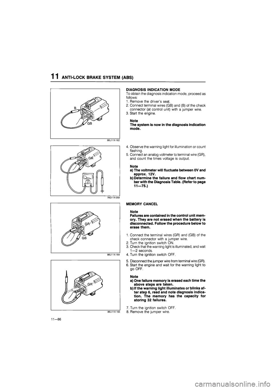
DIAGNOSIS INDICATION MODE
To obtain the diagnosis indication mode, proceed as
follows:
1. Remove the driver's seat.
2. Connect terminal wires (GB) and (B) of the check
connector (at control unit) with a jumper wire.
3. Start the engine.
Note
The system is now in the diagnosis indication
mode.
86U11X-162
4. Observe the warning light for illumination or count
flashing.
5. Connect an analog voltmeter to terminal wire (GR),
and count the times voltage is output.
Note
a) The voltmeter will fluctuate between OV and
approx. 12V.
b) Determine the failure and flow chart num-
ber with the Diagnosis Table. (Refer to page
11—75.)
76G11X-059
86U11X-164
86U11X-165
MEMORY CANCEL
Note
Failures are contained in the control unit mem-
ory. They are not erased when the battery is
disconnected. Follow the procedure below to
erase them.
1. Connect the terminal wires (GR) and (GB) of the
check connector with a jumper wire.
2. Turn the ignition switch ON.
3. Check that the warning light is illuminated, and wait
1—2 seconds.
4. Turn the ignition switch OFF.
5. Disconnect the jumper wire from terminal wire (GR).
6. Start the engine and wait for the warning light to
go OFF.
Note
a) One failure memory is erased each time the
above steps are taken.
b) If the warning light illuminates or blinks af-
ter step 6, read and note diagnosis indica-
tion. The memory has the capacity for
storing 32 failures.
7. Turn the ignition switch OFF.
8. Remove the jumper wire.
11-86