engine oil MAZDA MIATA 1991 Factory Service Manual
[x] Cancel search | Manufacturer: MAZDA, Model Year: 1991, Model line: MIATA, Model: MAZDA MIATA 1991Pages: 392, PDF Size: 29.45 MB
Page 294 of 392

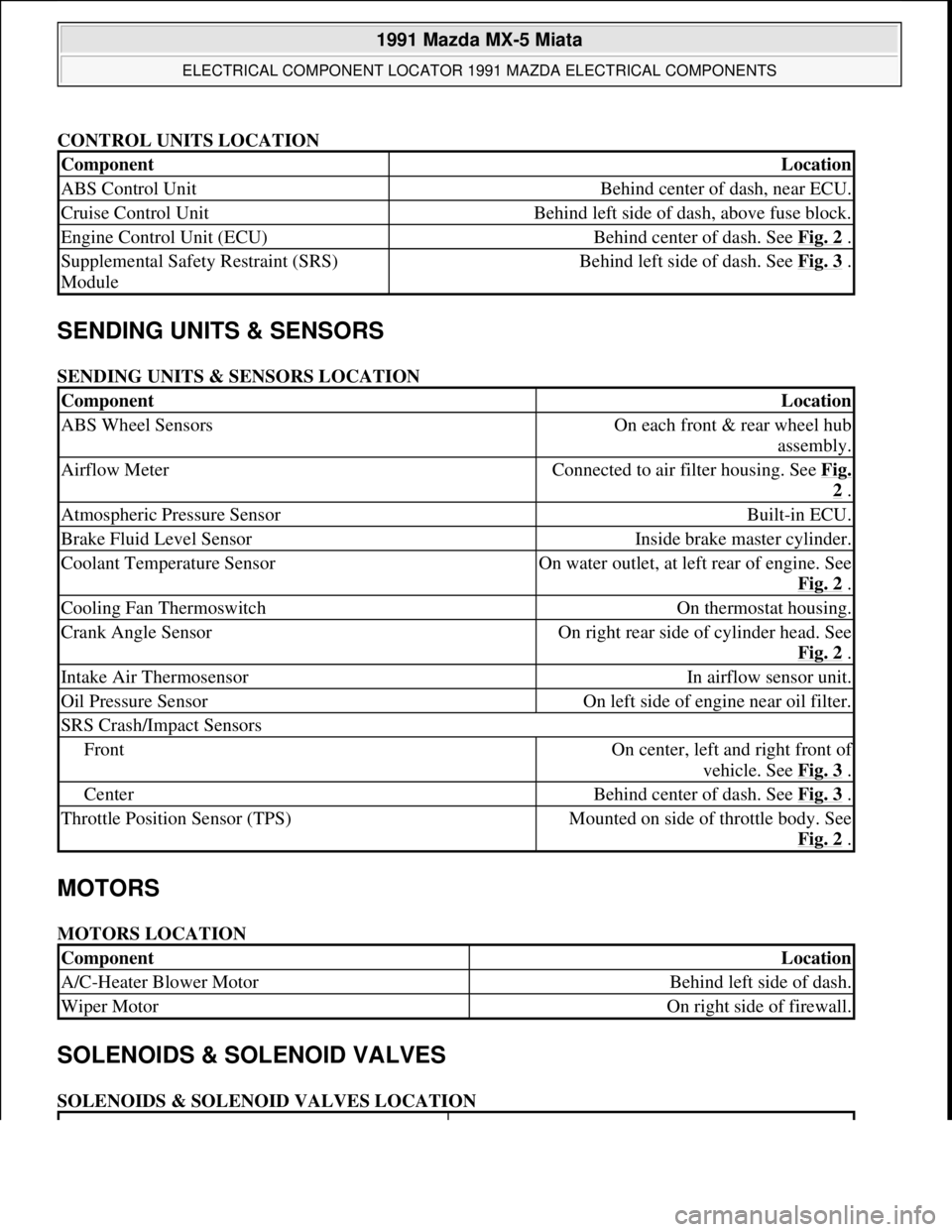
CONTROL UNITS LOCATION
SENDING UNITS & SENSORS
SENDING UNITS & SENSORS LOCATION
MOTORS
MOTORS LOCATION
SOLENOIDS & SOLENOID VALVES
SOLENOIDS & SOLENOID VALVES LOCATION
ComponentLocation
ABS Control UnitBehind center of dash, near ECU.
Cruise Control UnitBehind left side of dash, above fuse block.
Engine Control Unit (ECU)Behind center of dash. See Fig. 2 .
Supplemental Safety Restraint (SRS)
ModuleBehind left side of dash. See Fig. 3 .
ComponentLocation
ABS Wheel SensorsOn each front & rear wheel hub
assembly.
Airflow MeterConnected to air filter housing. See Fig.
2 .
Atmospheric Pressure SensorBuilt-in ECU.
Brake Fluid Level SensorInside brake master cylinder.
Coolant Temperature SensorOn water outlet, at left rear of engine. See
Fig. 2
.
Cooling Fan ThermoswitchOn thermostat housing.
Crank Angle SensorOn right rear side of cylinder head. See
Fig. 2
.
Intake Air ThermosensorIn airflow sensor unit.
Oil Pressure SensorOn left side of engine near oil filter.
SRS Crash/Impact Sensors
FrontOn center, left and right front of
vehicle. See Fig. 3
.
CenterBehind center of dash. See Fig. 3 .
Throttle Position Sensor (TPS)Mounted on side of throttle body. See
Fig. 2
.
ComponentLocation
A/C-Heater Blower MotorBehind left side of dash.
Wiper MotorOn right side of firewall.
1991 Mazda MX-5 Miata
ELECTRICAL COMPONENT LOCATOR 1991 MAZDA ELECTRICAL COMPONENTS
Microsoft
Sunday, July 05, 2009 2:15:23 PMPage 2 © 2005 Mitchell Repair Information Company, LLC.
Page 306 of 392

LOWER CONTROL ARM
Removal
Raise and support vehicle. Remove wheel assembly. Remove engine splash shield (if equipped). Remove
stabilizer bar from lower control arm. Remove strut rod (if equipped). Remove ball joint clamp bolt or pivot
nut, and separate ball joint from steering knuckle. Remove lower control arm pivot bolts. Remove lower control
arm.
Inspection
Check lower control arm for damage or cracks. Check bushings for deterioration and excessive wear. Check
ball joint for excessive wear. Examine dust boot for damage. Replace parts as necessary.
Bushing Replacement (Miata)
Cut or press old bushing from control arm. Coat new bushing with paraffin-based oil. Press new bushing into
control arm. To install, reverse removal procedure.
Bushing Replacement (MPV 4WD)
Cut away bushing inner collar. Using a vise and Remover/Installer (49-G033-102 and 49-FO27-009), push out
front bushing. Press out rear bushing using a press and Remover/Installer (49-U034-202 and 49-GO26-103). To
install front bushing, apply soapy water to bushing and use remover/installer to press in. To install rear bushing,
align arrows on bushing with marks on lower arm and use remover/installer to press in.
Bushing Replacement (MX-6 & 626)
Cut away bushing inner collar. Using a vise and Remover/Installer (49-GO34-2A0), push out bushing. To
install, apply soapy water to bushing and use remover/installer to press in. Always install bushing from outer
side of arm. Press in bushing until collar contacts arm.
Bushing Replacement (Protege & 323)
Using a vise and Remover/Installer Set (49-BO34-2A0), push out bushing. To install, apply soapy water to
bushing and use remover/installer to press in. Always install bushing from outer side of arm. Press in bushing
until collar contacts arm.
Bushing Replacement (929)
Cut away bushing outer collar. Using a vise and Remover/Installer (49-HO34-202 and 49-HO34-201), remove
bushing from control arm. To install, reverse removal procedure.
Bushing Replacement (RX7)
NOTE: Lower control arm bushings are not replaceable on MPV 2WD models. Replace
control arm assembly if bushings are worn or damaged.
1991 Mazda MX-5 Miata
SUSPENSION - FRONT 1990-91 SUSPENSION Front
Microsoft
Sunday, July 05, 2009 2:08:54 PMPage 8 © 2005 Mitchell Repair Information Company, LLC.
Page 307 of 392

Push out front bushing using a press and Remover (49-G030-627A). To remove rear bushing, install Bearing
Puller (49-0710-520) on bushing. DO NOT overtighten bearing puller nuts or lower arm will be distorted and
damaged. Press to push out rear bushing using Remover (49-G030-627A). To install both bushings, use
remover and Support Block (49-0823-146).
Installation (All Models)
To install, reverse removal procedure. Tighten lower control arm pivot bolts to specification with vehicle
resting on ground and suspension unloaded. See TORQUE SPECIFICATIONS
.
UPPER CONTROL ARM
Removal (Miata)
Raise and support vehicle. Remove wheel assembly. Remove engine splash shield. Remove ball joint pivot nut.
Use Puller (49-0118-850C) to separate ball joint from steering knuckle. Remove upper control arm pivot bolts.
Remove upper control arm.
Inspection
Check upper control arm for damage or cracks. Check bushings for deterioration and excessive wear. Check
ball joint for excessive wear. Examine dust boot for damage. Replace parts as necessary.
Bushing Replacement
Using a chisel, remove old bushing from control arm. Coat new bushing with grease. Press new bushing into
control arm.
Installation
To install, reverse removal procedure. Tighten upper control arm pivot bolts to specification with vehicle
resting on ground and suspension unloaded.
SHOCK ABSORBER
Removal (Miata)
Raise and support vehicle. Remove wheel assembly. Remove engine splash shield. Remove stabilizer link bolt.
Separate upper ball joint from steering knuckle. Loosen lower control arm pivot bolts. Remove shock absorber
upper mount nuts and lower bolt. Move lower control arm just enough to remove shock absorber. Be careful not
to damage brake line.
Disassembly
Clamp upper mount in vise. Loosen lock nut 2 turns only. Compress coil spring using coil spring compressor.
Remove lock nut and remainin
g components. Slowly release compressor tension.
1991 Mazda MX-5 Miata
SUSPENSION - FRONT 1990-91 SUSPENSION Front
Microsoft
Sunday, July 05, 2009 2:08:54 PMPage 9 © 2005 Mitchell Repair Information Company, LLC.
Page 320 of 392

Any modification to the exhaust system on turbo models, which reduces exhaust backpressure, will lead to lean
fuel mixtures and excessive spark advance. This could cause serious engine damage.
ELECTROSTATIC DISCHARGE SENSITIVE (ESD) PARTS
ENGINE OIL
FUEL SYSTEM SERVICE
HALOGEN BULBS
Halogen bulbs contain pressurized gas which may explode if overheated. DO NOT touch glass portion of bulb
with bare hands. Eye protection should be worn when handling or working around halogen bulbs.
HEADLIGHT RETRACTOR
RADIATOR CAP
RADIATOR FAN WARNING:Many solid state electrical components can be damaged by static
electricity (ESD). Some will display a warning label, but many will not.
Discharge personal static electricity by touching a metal ground point on
the vehicle prior to servicing any ESD sensitive component.
CAUTION: Never use non-detergent or straight mineral oil.
WARNING:Relieve fuel system pressure prior to servicing any fuel system
component (fuel injection models).
CAUTION: If headlight retractor freezes during cold weather operation, DO NOT
attempt to force mechanism. Headlights should be kept raised at all times
in cold weather. To raise them, use only headlight retractor switch. DO
NOT use headlight switch.
CAUTION: Always disconnect the fan motor when working near the radiator fan. The
fan is temperature controlled and could start at any time even when the
ignition key is in the OFF position. DO NOT loosen or remove radiator cap
when cooling system is hot.
WARNING:Keep hands away from radiator fan. Fan is controlled by a thermostatic
switch which may come on or run for up to 15 minutes even after engine
is turned off.
1991 Mazda MX-5 Miata
FUSES & CIRCUIT BREAKERS Fuses & Circuit Breakers 1990-95 Mazda
Microsoft
Sunday, July 05, 2009 2:15:54 PMPage 7 © 2005 Mitchell Repair Information Company, LLC.
Page 327 of 392

A/C-HEATER SYSTEM - MANUAL
1990-92 Manual A/C-Heater Systems
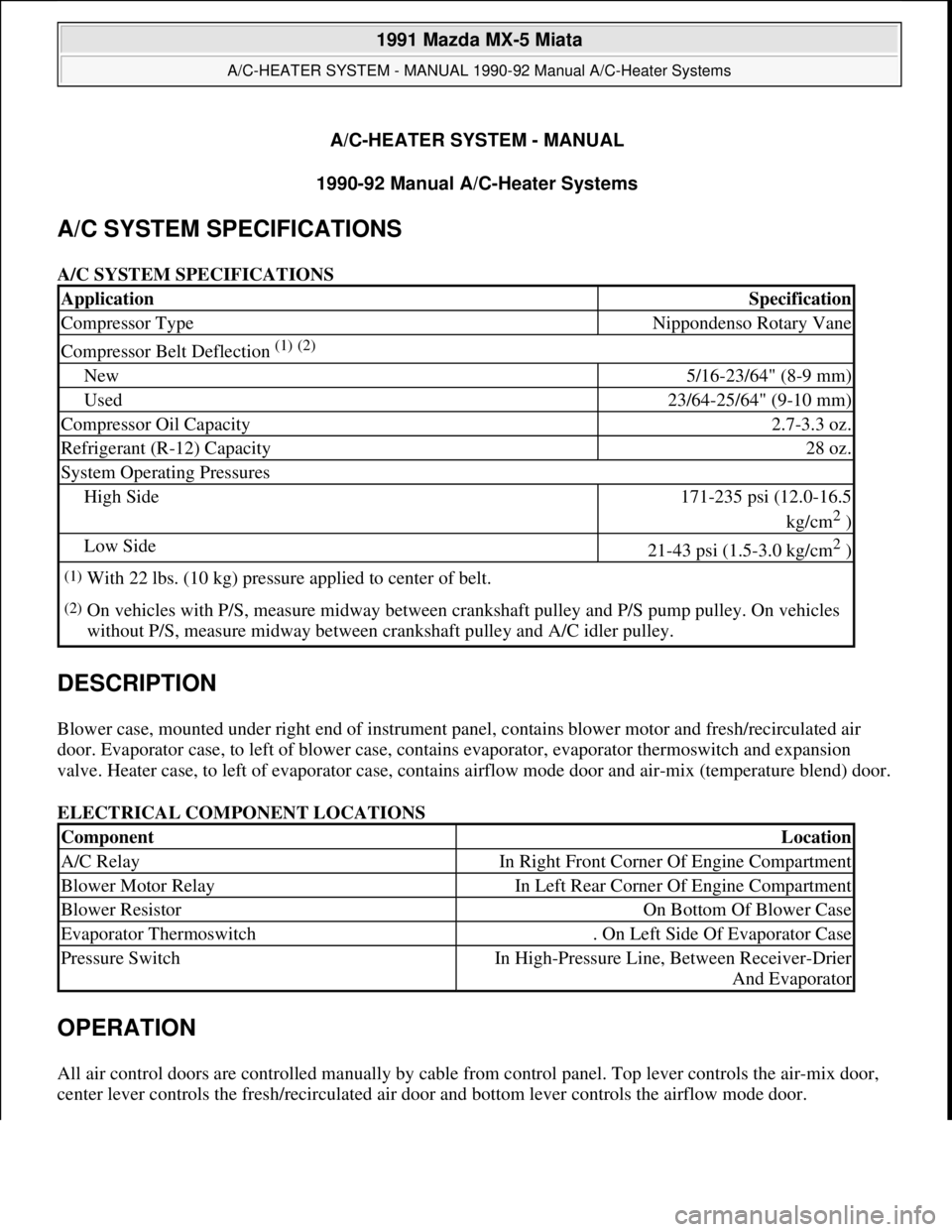
A/C SYSTEM SPECIFICATIONS
A/C SYSTEM SPECIFICATIONS
DESCRIPTION
Blower case, mounted under right end of instrument panel, contains blower motor and fresh/recirculated air
door. Evaporator case, to left of blower case, contains evaporator, evaporator thermoswitch and expansion
valve. Heater case, to left of evaporator case, contains airflow mode door and air-mix (temperature blend) door.
ELECTRICAL COMPONENT LOCATIONS
OPERATION
All air control doors are controlled manually by cable from control panel. Top lever controls the air-mix door,
center lever controls the fresh/recirculated air door and bottom lever controls the airflow mode door.
ApplicationSpecification
Compressor TypeNippondenso Rotary Vane
Compressor Belt Deflection (1) (2)
New5/16-23/64" (8-9 mm)
Used23/64-25/64" (9-10 mm)
Compressor Oil Capacity2.7-3.3 oz.
Refrigerant (R-12) Capacity28 oz.
System Operating Pressures
High Side171-235 psi (12.0-16.5
kg/cm
2 )
Low Side21-43 psi (1.5-3.0 kg/cm2 )
(1)With 22 lbs. (10 kg) pressure applied to center of belt.
(2)On vehicles with P/S, measure midway between crankshaft pulley and P/S pump pulley. On vehicles
without P/S, measure midway between crankshaft pulley and A/C idler pulley.
ComponentLocation
A/C RelayIn Right Front Corner Of Engine Compartment
Blower Motor RelayIn Left Rear Corner Of Engine Compartment
Blower ResistorOn Bottom Of Blower Case
Evaporator Thermoswitch. On Left Side Of Evaporator Case
Pressure SwitchIn High-Pressure Line, Between Receiver-Drier
And Evaporator
1991 Mazda MX-5 Miata
A/C-HEATER SYSTEM - MANUAL 1990-92 Manual A/C-Heater Systems
1991 Mazda MX-5 Miata
A/C-HEATER SYSTEM - MANUAL 1990-92 Manual A/C-Heater Systems
Microsoft
Sunday, July 05, 2009 2:11:52 PMPage 1 © 2005 Mitchell Repair Information Company, LLC.
Microsoft
Sunday, July 05, 2009 2:11:56 PMPage 1 © 2005 Mitchell Repair Information Company, LLC.
Page 340 of 392

LUBRICATION
CAPACITY
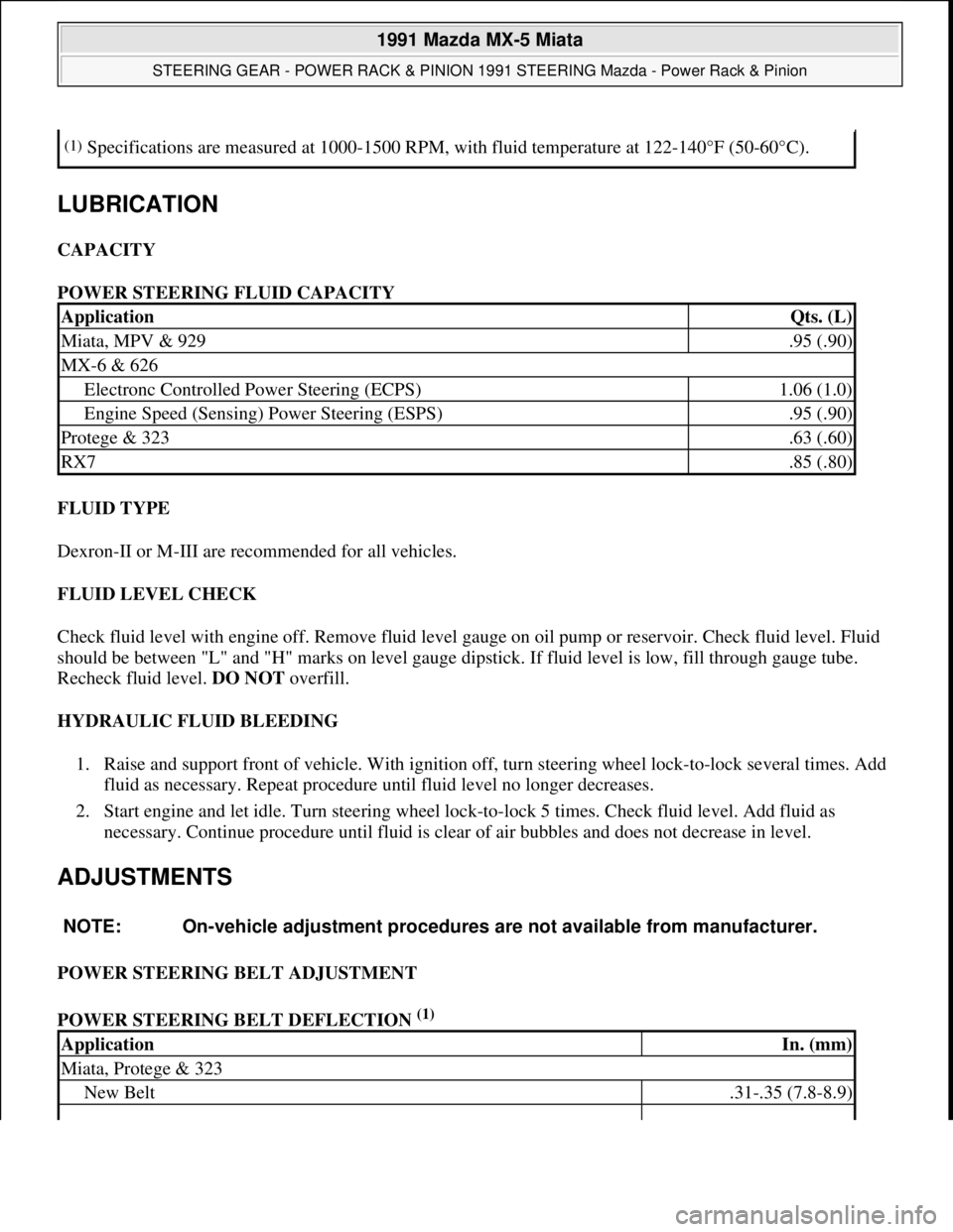
POWER STEERING FLUID CAPACITY
FLUID TYPE
Dexron-II or M-III are recommended for all vehicles.
FLUID LEVEL CHECK
Check fluid level with engine off. Remove fluid level gauge on oil pump or reservoir. Check fluid level. Fluid
should be between "L" and "H" marks on level gauge dipstick. If fluid level is low, fill through gauge tube.
Recheck fluid level. DO NOT overfill.
HYDRAULIC FLUID BLEEDING
1. Raise and support front of vehicle. With ignition off, turn steering wheel lock-to-lock several times. Add
fluid as necessary. Repeat procedure until fluid level no longer decreases.
2. Start engine and let idle. Turn steering wheel lock-to-lock 5 times. Check fluid level. Add fluid as
necessary. Continue procedure until fluid is clear of air bubbles and does not decrease in level.
ADJUSTMENTS
POWER STEERING BELT ADJUSTMENT
POWER STEERING BELT DEFLECTION
(1)
(1)Specifications are measured at 1000-1500 RPM, with fluid temperature at 122-140°F (50-60°C).
ApplicationQts. (L)
Miata, MPV & 929.95 (.90)
MX-6 & 626
Electronc Controlled Power Steering (ECPS)1.06 (1.0)
Engine Speed (Sensing) Power Steering (ESPS).95 (.90)
Protege & 323.63 (.60)
RX7.85 (.80)
NOTE: On-vehicle adjustment procedures are not available from manufacturer.
ApplicationIn. (mm)
Miata, Protege & 323
New Belt.31-.35 (7.8-8.9)
1991 Mazda MX-5 Miata
STEERING GEAR - POWER RACK & PINION 1991 STEERING Mazda - Power Rack & Pinion
Microsoft
Sunday, July 05, 2009 2:10:15 PMPage 3 © 2005 Mitchell Repair Information Company, LLC.
Page 390 of 392

Check timing belt for cracks, peeling, abrasion or other damage. Check tensioner bearing for looseness or
roughness of rotation. Inspect tensioner spring for stretching. Replace parts as necessary.
Installation (All Models)
1. Position notch on crankshaft sprocket to 12 o'clock position (aligned with mark on oil pump). Align
timing marks on camshaft sprocket(s). For SOHC, see Fig. 4
. For DOHC, see Fig. 5 or Fig. 7 . Ensure
crankshaft timing mark is at TDC. Install belt around crankshaft sprocket, then working in a
counterclockwise direction, route belt around camshaft sprocket(s).
2. Loosen timing belt tensioner lock bolt, and allow spring to apply tension on belt. Snug tensioner lock
bolt. Rotate crankshaft 2 complete turns in direction of normal engine rotation. Ensure timing marks
align. If timing marks are not aligned, remove belt, realign all timing marks, and repeat installation
procedure.
3. On all engines, check timing belt deflection with 22 lbs. (10 kg) of pressure applied to belt. See Fig. 8
.
Ensure timing belt deflection is within specification. See TIMING BELT DEFLECTION
table. Adjust
drive belts to proper tension.
TIMING BELT DEFLECTION
Application(1) Deflection - In. (mm)
1986-89.47-.51 (11.9-13.0)
1990-95
DOHC.35-.45 (9.0-11.5)
SOHC.43-.51 (11.0-13.0)
(1)Deflection measurement is with 22 lbs. (10 kg) of pressure applied to timing belt. See Fig. 8.
1991 Mazda MX-5 Miata
MAZDA 1.6L & 1.8L 4-Cylinder - 1986-95
Microsoft
Sunday, July 05, 2009 2:12:44 PMPage 9 © 2005 Mitchell Repair Information Company, LLC.