tow MAZDA MIATA 1991 Factory Service Manual
[x] Cancel search | Manufacturer: MAZDA, Model Year: 1991, Model line: MIATA, Model: MAZDA MIATA 1991Pages: 392, PDF Size: 29.45 MB
Page 131 of 392
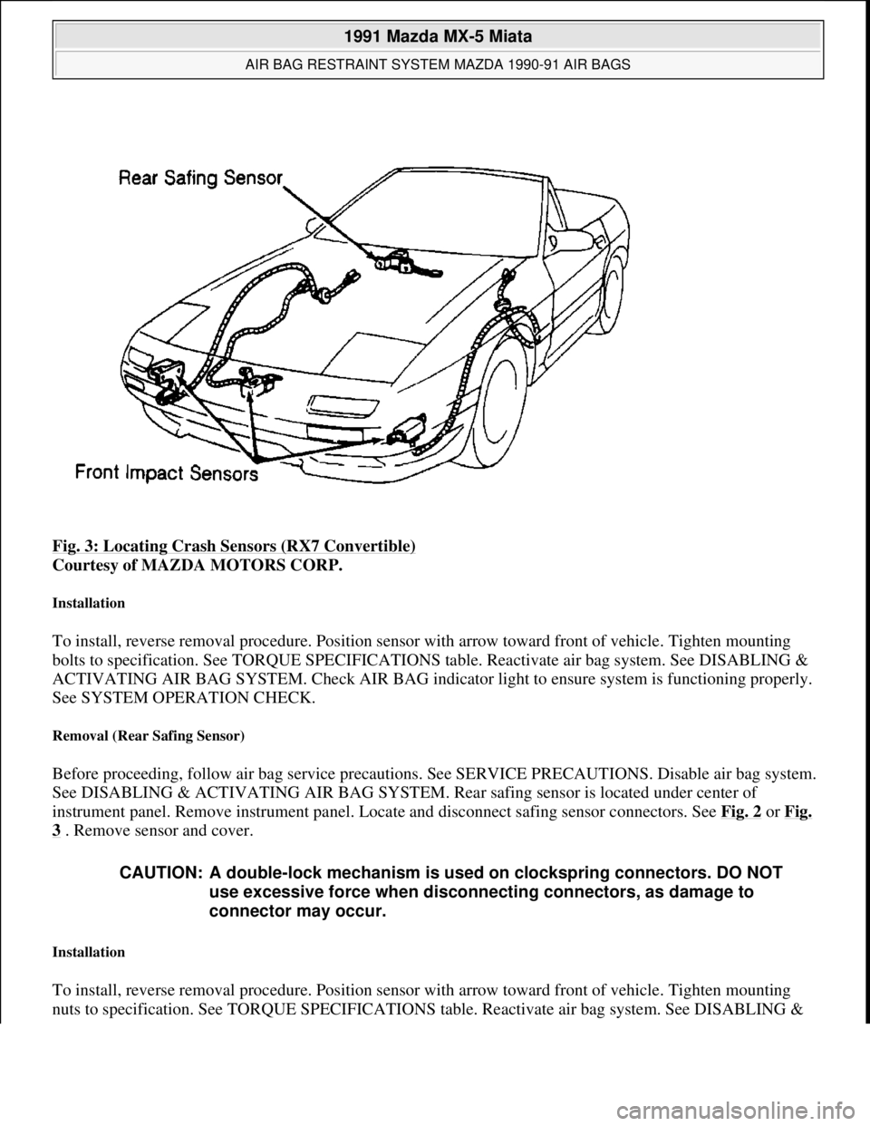
Fig. 3: Locating Crash Sensors (RX7 Convertible)
Courtesy of MAZDA MOTORS CORP.
Installation
To install, reverse removal procedure. Position sensor with arrow toward front of vehicle. Tighten mounting
bolts to specification. See TORQUE SPECIFICATIONS table. Reactivate air bag system. See DISABLING &
ACTIVATING AIR BAG SYSTEM. Check AIR BAG indicator light to ensure system is functioning properly.
See SYSTEM OPERATION CHECK.
Removal (Rear Safing Sensor)
Before proceeding, follow air bag service precautions. See SERVICE PRECAUTIONS. Disable air bag system.
See DISABLING & ACTIVATING AIR BAG SYSTEM. Rear safing sensor is located under center of
instrument panel. Remove instrument panel. Locate and disconnect safing sensor connectors. See Fig. 2
or Fig.
3 . Remove sensor and cover.
Installation
To install, reverse removal procedure. Position sensor with arrow toward front of vehicle. Tighten mounting
nuts to specification. See TORQUE SPECIFICATIONS table. Reactivate air ba
g system. See DISABLING &
CAUTION: A double-lock mechanism is used on clockspring connectors. DO NOT
use excessive force when disconnecting connectors, as damage to
connector may occur.
1991 Mazda MX-5 Miata
AIR BAG RESTRAINT SYSTEM MAZDA 1990-91 AIR BAGS
Microsoft
Sunday, July 05, 2009 2:11:16 PMPage 6 © 2005 Mitchell Repair Information Company, LLC.
Page 167 of 392
SPECIFICATIONS TABLE at end of article.
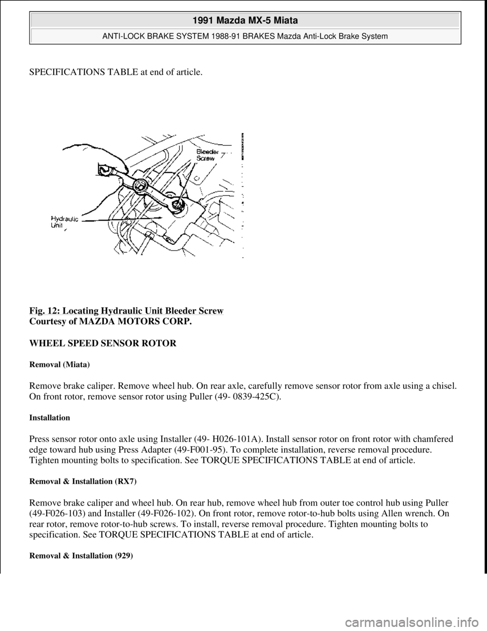
Fig. 12: Locating Hydraulic Unit Bleeder Screw
Courtesy of MAZDA MOTORS CORP.
WHEEL SPEED SENSOR ROTOR
Removal (Miata)
Remove brake caliper. Remove wheel hub. On rear axle, carefully remove sensor rotor from axle using a chisel.
On front rotor, remove sensor rotor using Puller (49- 0839-425C).
Installation
Press sensor rotor onto axle using Installer (49- H026-101A). Install sensor rotor on front rotor with chamfered
edge toward hub using Press Adapter (49-F001-95). To complete installation, reverse removal procedure.
Tighten mounting bolts to specification. See TORQUE SPECIFICATIONS TABLE at end of article.
Removal & Installation (RX7)
Remove brake caliper and wheel hub. On rear hub, remove wheel hub from outer toe control hub using Puller
(49-F026-103) and Installer (49-F026-102). On front rotor, remove rotor-to-hub bolts using Allen wrench. On
rear rotor, remove rotor-to-hub screws. To install, reverse removal procedure. Tighten mounting bolts to
specification. See TORQUE SPECIFICATIONS TABLE at end of article.
Removal & Installation (929)
1991 Mazda MX-5 Miata
ANTI-LOCK BRAKE SYSTEM 1988-91 BRAKES Mazda Anti-Lock Brake System
Microsoft
Sunday, July 05, 2009 2:17:32 PMPage 15 © 2005 Mitchell Repair Information Company, LLC.
Page 168 of 392
Remove brake caliper and wheel hub. On rear axle, carefully remove sensor rotor from axle using chisel. On
front rotor, remove sensor rotor using Puller (49-0839-425C). To install, press sensor rotors onto axle and front
rotor using Installer (49-H026-101A). On front rotor, install sensor rotor with chamfered edge toward hub. To
complete installation, reverse removal procedure. Tighten mounting bolts to specification. See TORQUE
SPECIFICATIONS TABLE at end of article.
WHEEL SPEED SENSOR
Removal & Installation
Unplug wheel sensor connector. Remove sensor bolt. Remove wheel sensor from vehicle. To install, reverse
removal procedure. On RX7, adjust wheel sensor so clearance between sensor and rotor is .016-.039" (.40-1.0
mm). Tighten mounting bolts to specification. See TORQUE SPECIFICATIONS TABLE at end of article.
DIAGNOSING ABS SYSTEM
ABS TESTER OPERATION
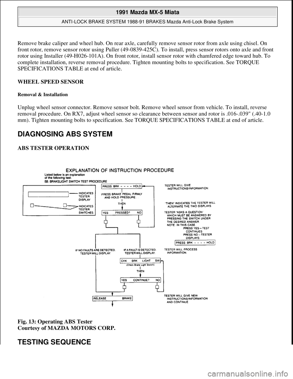
Fig. 13: Operating ABS Tester
Courtesy of MAZDA MOTORS CORP.
TESTING SEQUENCE
1991 Mazda MX-5 Miata
ANTI-LOCK BRAKE SYSTEM 1988-91 BRAKES Mazda Anti-Lock Brake System
Microsoft
Sunday, July 05, 2009 2:17:32 PMPage 16 © 2005 Mitchell Repair Information Company, LLC.
Page 208 of 392
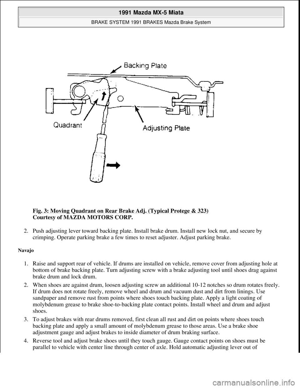
Fig. 3: Moving Quadrant on Rear Brake Adj. (Typical Protege & 323)
Courtesy of MAZDA MOTORS CORP.
2. Push adjusting lever toward backing plate. Install brake drum. Install new lock nut, and secure by
crimping. Operate parking brake a few times to reset adjuster. Adjust parking brake.
Navajo
1. Raise and support rear of vehicle. If drums are installed on vehicle, remove cover from adjusting hole at
bottom of brake backing plate. Turn adjusting screw with a brake adjusting tool until shoes drag against
brake drum and lock drum.
2. When shoes are against drum, loosen adjusting screw an additional 10-12 notches so drum rotates freely.
If drum does not rotate freely, remove wheel and drum and vacuum dust and dirt from linings. Use
sandpaper and remove rust from points where shoes touch backing plate. Apply a light coating of
molybdenum grease to brake shoe-to-backing plate contact points. Install wheel and drum and adjust
shoes.
3. To adjust brakes with rear drums removed, first clean all rust and dirt on points where shoes touch
backing plate and apply a small amount of molybdenum grease to those areas. Use a brake shoe
adjustment gauge and adjust brakes to inside diameter of drum braking surface.
4. Reverse tool and adjust brake shoes until they touch gauge. Gauge contact points on shoes must be
parallel to vehicle with center line throu
gh center of axle. Hold automatic adjusting lever out of
1991 Mazda MX-5 Miata
BRAKE SYSTEM 1991 BRAKES Mazda Brake System
Microsoft
Sunday, July 05, 2009 2:18:08 PMPage 5 © 2005 Mitchell Repair Information Company, LLC.
Page 211 of 392
2. Release parking brake lever. Using a screwdriver, reach through parking brake handle hole in console and
rotate adjusting screw until stroke is 6-8 notches. Ensure rear wheels rotate freely. Ensure parking brake
warning light illuminates when brake lever is pulled one notch.
Miata, MX-6, MPV, Protege, RX7, 323, 626
1. On models with rear disc brakes, depress brake pedal several times. On models with rear drum brakes,
start engine and depress brake pedal several times while vehicle is moving in Reverse. Stop engine.
2. On all models, pull parking brake lever with a force of 22 lbs. (10 kg). If stroke is 5-7 notches, parking
brake is properly adjusted. If stroke is not 5-7 notches, raise and support rear of vehicle. Release parking
brake lever.
3. Rotate cable adjusting nut at lever end of cable (under console cover) until stroke is within specification.
On models equipped with rear disc brakes, ensure clearance between stopper and lever (at each caliper) is
not less than .08" (2 mm) on RX7, or zero on all other models. On all models, ensure parking brake
warning light illuminates when brake lever is pulled one notch.
PARKING BRAKE SHOES
929
Raise and support vehicle. Remove rear wheels. Remove service plug from rotor. Using a screwdriver, rotate
star wheel adjuster toward axle until rotor locks. Rotate adjuster in opposite direction 3-5 notches. Ensure rotors
turn freely and parking brake functions properly. Install service plug and rear wheels.
PEDAL FREE PLAY
Depress pedal a few times to eliminate vacuum. Pedal free play should be .16-.28" (4-7 mm). Adjust play by
loosening push rod lock nut. Turn push rod until correct free play is obtained. Tighten push rod lock nut.
PEDAL HEIGHT & STOPLIGHT SWITCH
1. Released pedal height is measured from carpet surface on vertical portion of firewall to pedal pad center.
Disconnect stoplight switch electrical connector. Loosen lock nut on stoplight switch. Move switch away
from pedal. Loosen push rod lock nut. Turn rod until correct pedal height is obtained. See BRAKE
PEDAL HEIGHT SPECIFICATIONS .
2. Adjust pedal free play. See PEDAL FREE PLAY
under ADJUSTMENTS. Tighten push rod lock nut.
Rotate stoplight switch until it contacts pedal and then rotate an additional 1/2 turn. Tighten stoplight
switch lock nut. Reconnect stoplight switch electrical connector.
3. Applied pedal height is measured from angled portion of firewall (without carpet) to pedal pad center.
Start engine. On B2200, B2600i and MPV, depress brake pedal with 33 lbs. (15 kg) pressure. On all other
models, depress brake pedal with 132 lbs. (60 k
g) pressure. tension should be checked and adjusted.
NOTE: Pedal height and stoplight switch information is not available for Navajo.
1991 Mazda MX-5 Miata
BRAKE SYSTEM 1991 BRAKES Mazda Brake System
Microsoft
Sunday, July 05, 2009 2:18:08 PMPage 8 © 2005 Mitchell Repair Information Company, LLC.
Page 213 of 392

procedure.
Fig. 5: Exploded View of Front Disc Brake Assembly (Protege & 323)
Courtesy of MAZDA MOTORS CORP.
Removal (Navajo)
1. To prevent master cylinder overflow when caliper piston is depressed, remove and discard some brake
fluid from master cylinder. Raise vehicle, and support using safety stands.
2. Remove front wheel assembly. Place a large "C" clamp on caliper. See Fig. 9
. Tighten clamp to bottom
piston in cylinder bore. Remove clamp.
3. Remove dirt around caliper pin tabs. Tap upper caliper pin toward inboard side of vehicle until pin tabs
1991 Mazda MX-5 Miata
BRAKE SYSTEM 1991 BRAKES Mazda Brake System
Microsoft
Sunday, July 05, 2009 2:18:08 PMPage 10 © 2005 Mitchell Repair Information Company, LLC.
Page 228 of 392
2. To install, turn caliper piston clockwise using Disc Brake Piston Wrench (49-FA18-602) to retract caliper
piston. Ensure groove in piston aligns with alignment pin on back of inner pad. To install remaining
components, reverse removal procedure.
Removal & Installation (929)
Raise and support rear of vehicle. Remove wheel. Remove lower guide bolt from caliper. Rotate caliper upward
and secure with rope. Remove pads and shims. Replace pad if lining thickness is less than .08" (2.0 mm). To
install, reverse removal procedure.
REAR BRAKE CALIPER
Removal & Installation
1. Raise and support rear of vehicle. On all models except 929, release parking brake and disconnect parking
brake cable from caliper. On all models, disconnect brake hose from caliper.
2. On Miata, Protege and 323, remove manual adjustment gear concealment plug from caliper. See Fig. 15
.
Insert an appropriate size Allen wrench through hole and turn manual adjustment gear counterclockwise
to retract caliper piston.
3. On all models, remove lower guide bolt from caliper. Rotate caliper upward. Pull caliper toward center of
vehicle to slide it off of caliper mount. To install, reverse removal procedure. Bleed hydraulic system.
REAR BRAKE ROTOR
Removal & Installation (Miata, Protege, RX7, 323 & 929)
Remove rear brake caliper. Remove rotor-to-hub screws. Remove rotor. Machine rotor if lateral runout exceeds
specification. Replace rotor if measured thickness is less than specified minimum thickness. See DISC BRAKE
SPECIFICATIONS at end of article. To install, reverse removal procedure.
Removal & Installation (MX-6 & 626)
1. Remove rear caliper, and wire aside. Remove grease cap. Remove lock nut. Remove rotor. Machine rotor
if lateral runout exceeds specification. Replace rotor if measured thickness is less than specified minimum
thickness. See DISC BRAKE SPECIFICATIONS
at end of article.
2. To install, reverse removal procedure. Tighten lock nut to 73-131 ft. lbs. (99-178 N.m). Check end play at
grease cap. If end play exceeds .008" (.20 mm), replace wheel bearings.
REAR BRAKE SHOES
Removal (B2200, B2600i & MPV)
With brake drum removed, remove brake shoe return springs, retaining springs and guide pins. See Fig. 16 or
Fig. 17
. Remove brake shoes. Remove parking brake strut, and disconnect parking brake cable from operating
lever of secondar
y shoe. Minimum lining thickness is .04" (1 mm).
1991 Mazda MX-5 Miata
BRAKE SYSTEM 1991 BRAKES Mazda Brake System
Microsoft
Sunday, July 05, 2009 2:18:08 PMPage 25 © 2005 Mitchell Repair Information Company, LLC.
Page 230 of 392
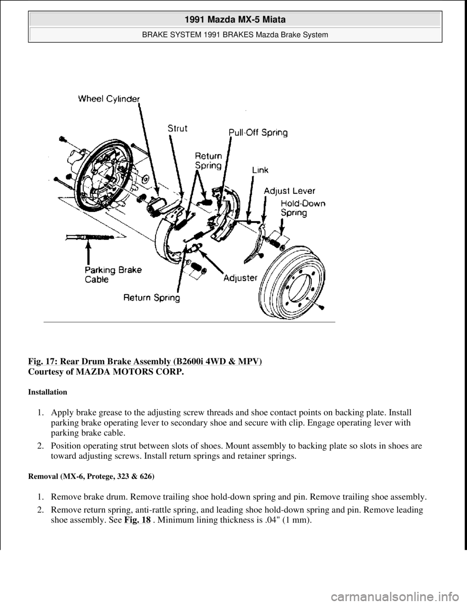
Fig. 17: Rear Drum Brake Assembly (B2600i 4WD & MPV)
Courtesy of MAZDA MOTORS CORP.
Installation
1. Apply brake grease to the adjusting screw threads and shoe contact points on backing plate. Install
parking brake operating lever to secondary shoe and secure with clip. Engage operating lever with
parking brake cable.
2. Position operating strut between slots of shoes. Mount assembly to backing plate so slots in shoes are
toward adjusting screws. Install return springs and retainer springs.
Removal (MX-6, Protege, 323 & 626)
1. Remove brake drum. Remove trailing shoe hold-down spring and pin. Remove trailing shoe assembly.
2. Remove return spring, anti-rattle spring, and leading shoe hold-down spring and pin. Remove leading
shoe assembly. See Fig. 18
. Minimum lining thickness is .04" (1 mm).
1991 Mazda MX-5 Miata
BRAKE SYSTEM 1991 BRAKES Mazda Brake System
Microsoft
Sunday, July 05, 2009 2:18:08 PMPage 27 © 2005 Mitchell Repair Information Company, LLC.
Page 232 of 392

Fig. 19: Examining Rear Brake Assemblies (Navajo)
Courtesy of FORD MOTOR CO.
2. Move outboard side of adjusting screw upward, and back off pivot nut as far as possible. Pull adjusting
lever, cable and adjusting spring down and toward rear to unhook pivot hook from large hole in
secondary shoe. DO NOT pry pivot hook from hole.
3. Remove adjusting spring and adjusting lever. Remove secondary shoe-to-anchor spring. Remove primary
1991 Mazda MX-5 Miata
BRAKE SYSTEM 1991 BRAKES Mazda Brake System
Microsoft
Sunday, July 05, 2009 2:18:08 PMPage 29 © 2005 Mitchell Repair Information Company, LLC.
Page 295 of 392
SWITCHES
SWITCHES LOCATION
MISCELLANEOUS
MISCELLANEOUS LOCATION
COMPONENT LOCATION GRAPHICS
ComponentLocation
Idle Speed Control SolenoidOn throttle body.
Purge Control Solenoid ValveOn right side of engine compartment, on shock
tower.
ComponentLocation
A/C Pressure SwitchOn high pressure refrigerant line.
Back-Up Light SwitchOn left side of transmission.
Clutch SwitchOn bracket, above clutch pedal. See Fig. 2 .
Neutral SwitchOn right rear side of transmission. See Fig. 2 .
Parking Brake SwitchOn base of parking brake lever.
Power Steering Pressure SwitchOn power steering housing assembly. See Fig. 2 .
Seat Belt Buckle SwitchOn driver's side seat belt buckle.
Stoplight SwitchOn bracket, above brake pedal. See Fig. 2 .
ComponentLocation
Diagnostic Check ConnectorOn left rear of engine compartment, near master cylinder. See Fig. 2 .
IgniterOn right rear corner of engine compartment, near fuse/relay block. See
Fig. 2
.
SRS Back-Up BatteryMounted below SRS control unit. See Fig. 3 .
NOTE: Figures may show multiple component locations. Refer to appropriate table for
proper figure references.
1991 Mazda MX-5 Miata
ELECTRICAL COMPONENT LOCATOR 1991 MAZDA ELECTRICAL COMPONENTS
Microsoft
Sunday, July 05, 2009 2:15:23 PMPage 3 © 2005 Mitchell Repair Information Company, LLC.