height MAZDA MIATA 1991 Factory Service Manual
[x] Cancel search | Manufacturer: MAZDA, Model Year: 1991, Model line: MIATA, Model: MAZDA MIATA 1991Pages: 392, PDF Size: 29.45 MB
Page 183 of 392
Courtesy of MAZDA MOTORS CORP.
ADJUSTMENTS
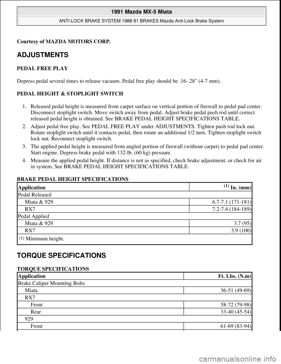
PEDAL FREE PLAY
Depress pedal several times to release vacuum. Pedal free play should be .16-.28" (4-7 mm).
PEDAL HEIGHT & STOPLIGHT SWITCH
1. Released pedal height is measured from carpet surface on vertical portion of firewall to pedal pad center.
Disconnect stoplight switch. Move switch away from pedal. Adjust brake pedal push rod until correct
released pedal height is obtained. See BRAKE PEDAL HEIGHT SPECIFICATIONS TABLE.
2. Adjust pedal free play. See PEDAL FREE PLAY under ADJUSTMENTS. Tighten push rod lock nut.
Rotate stoplight switch until it contacts pedal, then rotate an additional 1/2 turn. Tighten stoplight switch
lock nut. Reconnect stoplight switch.
3. The applied pedal height is measured from angled portion of firewall (without carpet) to pedal pad center.
Start engine. Depress brake pedal with 132-lb. (60 kg) pressure.
4. Measure the applied pedal height. If distance is not as specified, check brake adjustment, or check for air
in system. See BRAKE PEDAL HEIGHT SPECIFICATIONS TABLE.
BRAKE PEDAL HEIGHT SPECIFICATIONS
TORQUE SPECIFICATIONS
TORQUE SPECIFICATIONS
Application(1) In. (mm)
Pedal Released
Miata & 9296.7-7.1 (171-181)
RX77.2-7.4 (184-189)
Pedal Applied
Miata & 9293.7 (95)
RX73.9 (100)
(1)Minimum height.
ApplicationFt. Lbs. (N.m)
Brake Caliper Mounting Bolts
Miata36-51 (49-69)
RX7
Front58-72 (79-98)
Rear33-40 (45-54)
929
Front61-69 (83-94)
1991 Mazda MX-5 Miata
ANTI-LOCK BRAKE SYSTEM 1988-91 BRAKES Mazda Anti-Lock Brake System
Microsoft
Sunday, July 05, 2009 2:17:32 PMPage 31 © 2005 Mitchell Repair Information Company, LLC.
Page 211 of 392
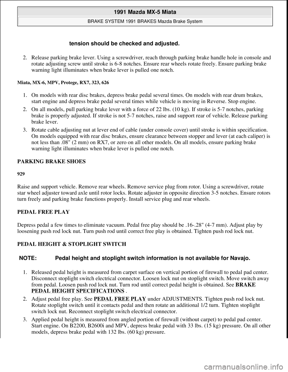
2. Release parking brake lever. Using a screwdriver, reach through parking brake handle hole in console and
rotate adjusting screw until stroke is 6-8 notches. Ensure rear wheels rotate freely. Ensure parking brake
warning light illuminates when brake lever is pulled one notch.
Miata, MX-6, MPV, Protege, RX7, 323, 626
1. On models with rear disc brakes, depress brake pedal several times. On models with rear drum brakes,
start engine and depress brake pedal several times while vehicle is moving in Reverse. Stop engine.
2. On all models, pull parking brake lever with a force of 22 lbs. (10 kg). If stroke is 5-7 notches, parking
brake is properly adjusted. If stroke is not 5-7 notches, raise and support rear of vehicle. Release parking
brake lever.
3. Rotate cable adjusting nut at lever end of cable (under console cover) until stroke is within specification.
On models equipped with rear disc brakes, ensure clearance between stopper and lever (at each caliper) is
not less than .08" (2 mm) on RX7, or zero on all other models. On all models, ensure parking brake
warning light illuminates when brake lever is pulled one notch.
PARKING BRAKE SHOES
929
Raise and support vehicle. Remove rear wheels. Remove service plug from rotor. Using a screwdriver, rotate
star wheel adjuster toward axle until rotor locks. Rotate adjuster in opposite direction 3-5 notches. Ensure rotors
turn freely and parking brake functions properly. Install service plug and rear wheels.
PEDAL FREE PLAY
Depress pedal a few times to eliminate vacuum. Pedal free play should be .16-.28" (4-7 mm). Adjust play by
loosening push rod lock nut. Turn push rod until correct free play is obtained. Tighten push rod lock nut.
PEDAL HEIGHT & STOPLIGHT SWITCH
1. Released pedal height is measured from carpet surface on vertical portion of firewall to pedal pad center.
Disconnect stoplight switch electrical connector. Loosen lock nut on stoplight switch. Move switch away
from pedal. Loosen push rod lock nut. Turn rod until correct pedal height is obtained. See BRAKE
PEDAL HEIGHT SPECIFICATIONS .
2. Adjust pedal free play. See PEDAL FREE PLAY
under ADJUSTMENTS. Tighten push rod lock nut.
Rotate stoplight switch until it contacts pedal and then rotate an additional 1/2 turn. Tighten stoplight
switch lock nut. Reconnect stoplight switch electrical connector.
3. Applied pedal height is measured from angled portion of firewall (without carpet) to pedal pad center.
Start engine. On B2200, B2600i and MPV, depress brake pedal with 33 lbs. (15 kg) pressure. On all other
models, depress brake pedal with 132 lbs. (60 k
g) pressure. tension should be checked and adjusted.
NOTE: Pedal height and stoplight switch information is not available for Navajo.
1991 Mazda MX-5 Miata
BRAKE SYSTEM 1991 BRAKES Mazda Brake System
Microsoft
Sunday, July 05, 2009 2:18:08 PMPage 8 © 2005 Mitchell Repair Information Company, LLC.
Page 212 of 392
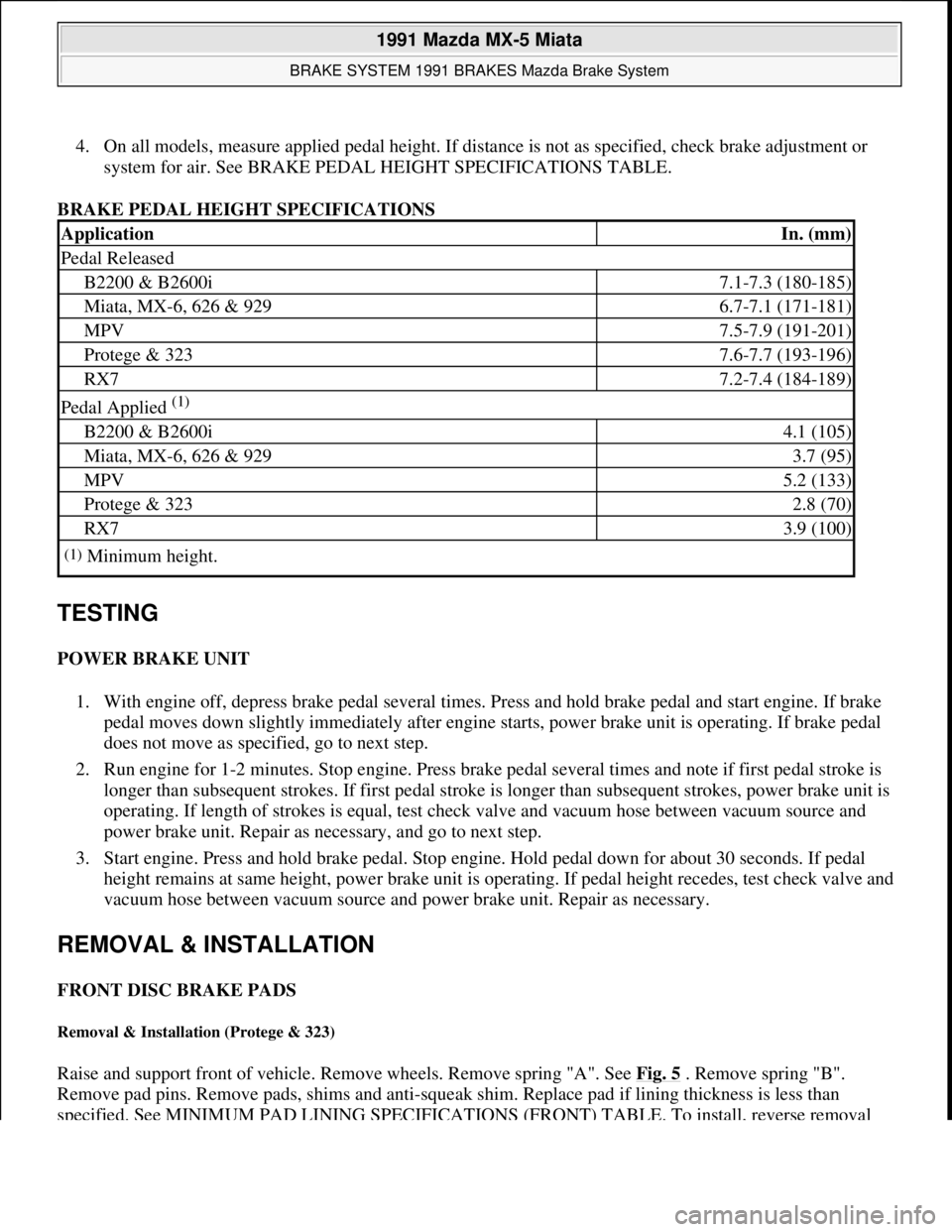
4. On all models, measure applied pedal height. If distance is not as specified, check brake adjustment or
system for air. See BRAKE PEDAL HEIGHT SPECIFICATIONS TABLE.
BRAKE PEDAL HEIGHT SPECIFICATIONS
TESTING
POWER BRAKE UNIT
1. With engine off, depress brake pedal several times. Press and hold brake pedal and start engine. If brake
pedal moves down slightly immediately after engine starts, power brake unit is operating. If brake pedal
does not move as specified, go to next step.
2. Run engine for 1-2 minutes. Stop engine. Press brake pedal several times and note if first pedal stroke is
longer than subsequent strokes. If first pedal stroke is longer than subsequent strokes, power brake unit is
operating. If length of strokes is equal, test check valve and vacuum hose between vacuum source and
power brake unit. Repair as necessary, and go to next step.
3. Start engine. Press and hold brake pedal. Stop engine. Hold pedal down for about 30 seconds. If pedal
height remains at same height, power brake unit is operating. If pedal height recedes, test check valve and
vacuum hose between vacuum source and power brake unit. Repair as necessary.
REMOVAL & INSTALLATION
FRONT DISC BRAKE PADS
Removal & Installation (Protege & 323)
Raise and support front of vehicle. Remove wheels. Remove spring "A". See Fig. 5 . Remove spring "B".
Remove pad pins. Remove pads, shims and anti-squeak shim. Replace pad if lining thickness is less than
specified. See MINIMUM PAD LINING SPECIFICATIONS (FRONT) TABLE. To install, reverse removal
ApplicationIn. (mm)
Pedal Released
B2200 & B2600i7.1-7.3 (180-185)
Miata, MX-6, 626 & 9296.7-7.1 (171-181)
MPV7.5-7.9 (191-201)
Protege & 3237.6-7.7 (193-196)
RX77.2-7.4 (184-189)
Pedal Applied (1)
B2200 & B2600i4.1 (105)
Miata, MX-6, 626 & 9293.7 (95)
MPV5.2 (133)
Protege & 3232.8 (70)
RX73.9 (100)
(1)Minimum height.
1991 Mazda MX-5 Miata
BRAKE SYSTEM 1991 BRAKES Mazda Brake System
Microsoft
Sunday, July 05, 2009 2:18:08 PMPage 9 © 2005 Mitchell Repair Information Company, LLC.
Page 274 of 392
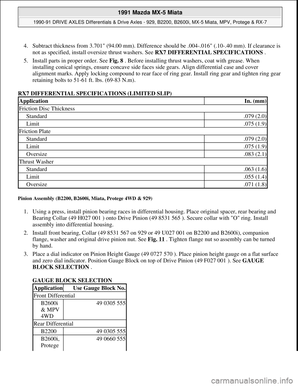
4. Subtract thickness from 3.701" (94.00 mm). Difference should be .004-.016" (.10-.40 mm). If clearance is
not as specified, install oversize thrust washers. See RX7 DIFFERENTIAL SPECIFICATIONS
.
5. Install parts in proper order. See Fig. 8
. Before installing thrust washers, coat with grease. When
installing conical springs, ensure concave side faces side gears. Align differential case and cover
alignment marks. Apply locking compound to rear face of ring gear. Install ring gear and tighten ring gear
retaining bolts to 51-61 ft. lbs. (69-83 N.m).
RX7 DIFFERENTIAL SPECIFICATIONS (LIMITED SLIP)
Pinion Assembly (B2200, B2600i, Miata, Protege 4WD & 929)
1. Using a press, install pinion bearing races in differential housing. Place original spacer, rear bearing and
Bearing Collar (49 H027 001 ) onto Drive Pinion (49 8531 565 ). Secure collar with "O" ring. Install
assembly into differential housing.
2. Install front bearing, Collar (49 8531 567 on 929 or 49 U027 001 on B2200 and B2600i), companion
flange, washer and original drive pinion nut. See Fig. 11
. Tighten flange nut so assembly can be turned
by hand.
3. Place a dial indicator on Pinion Height Gauge (49 0727 570 ). Place pinion height gauge on a flat surface
and zero dial indicator. Position Gauge Block on top of Drive Pinion (49 F027 001 ). See GAUGE
BLOCK SELECTION .
GAUGE BLOCK SELECTION
ApplicationIn. (mm)
Friction Disc Thickness
Standard.079 (2.0)
Limit.075 (1.9)
Friction Plate
Standard.079 (2.0)
Limit.075 (1.9)
Oversize.083 (2.1)
Thrust Washer
Standard.063 (1.6)
Limit.055 (1.4)
Oversize.071 (1.8)
ApplicationUse Gauge Block No.
Front Differential
B2600i
& MPV
4WD49 0305 555
Rear Differential
B220049 0305 555
B2600i,
Protege 49 0660 555
1991 Mazda MX-5 Miata
1990-91 DRIVE AXLES Differentials & Drive Axles - 929, B2200, B2600i, MX-5 Miata, MPV, Protege & RX-7
Microsoft
Sunday, July 05, 2009 2:17:01 PMPage 16 © 2005 Mitchell Repair Information Company, LLC.
Page 275 of 392
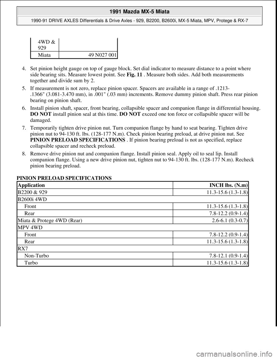
4. Set pinion height gauge on top of gauge block. Set dial indicator to measure distance to a point where
side bearing sits. Measure lowest point. See Fig. 11
. Measure both sides. Add both measurements
together and divide sum by 2.
5. If measurement is not zero, replace pinion spacer. Spacers are available in a range of .1213-
.1366" (3.081-3.470 mm), in .001" (.03 mm) increments. Remove dummy pinion shaft. Press rear pinion
bearing on pinion shaft.
6. Install pinion shaft, spacer, front bearing, collapsible spacer and companion flange in differential housing.
DO NOT install pinion seal at this time. DO NOT exceed one ton force or collapsible spacer will be
damaged.
7. Temporarily tighten drive pinion nut. Turn companion flange by hand to seat bearing. Tighten drive
pinion nut to 94-130 ft. lbs. (128-177 N.m). Check pinion bearing preload, at drive pinion nut. See
PINION PRELOAD SPECIFICATIONS
. If pinion bearing preload is not as specified, replace
collapsible spacer and recheck preload.
8. Remove drive pinion nut and companion flange. Install pinion seal. Apply oil to seal lip. Install
companion flange. Using a new drive pinion nut, tighten nut to 94-130 ft. lbs. (128-177 N.m). Recheck
pinion bearing preload.
PINION PRELOAD SPECIFICATIONS
4WD &
929
Miata49 N027 001
ApplicationINCH lbs. (N.m)
B2200 & 92911.3-15.6 (1.3-1.8)
B2600i 4WD
Front11.3-15.6 (1.3-1.8)
Rear7.8-12.2 (0.9-1.4)
Miata & Protege 4WD (Rear)2.6-6.1 (0.3-0.7)
MPV 4WD
Front7.8-12.2 (0.9-1.4)
Rear11.3-15.6 (1.3-1.8)
RX7
Non-Turbo7.8-12.1 (0.9-1.4)
Turbo11.3-15.6 (1.3-1.8)
1991 Mazda MX-5 Miata
1990-91 DRIVE AXLES Differentials & Drive Axles - 929, B2200, B2600i, MX-5 Miata, MPV, Protege & RX-7
Microsoft
Sunday, July 05, 2009 2:17:01 PMPage 17 © 2005 Mitchell Repair Information Company, LLC.
Page 277 of 392
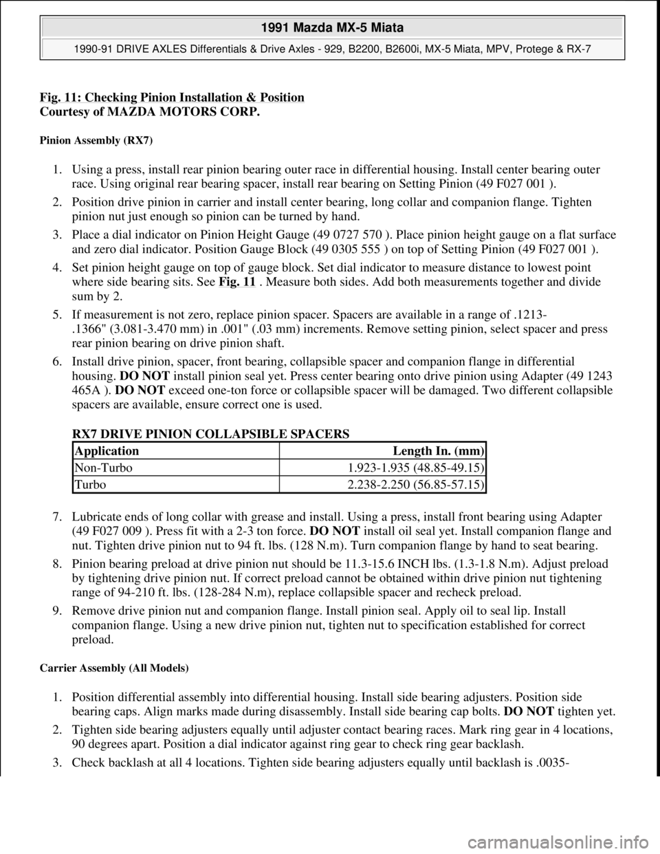
Fig. 11: Checking Pinion Installation & Position
Courtesy of MAZDA MOTORS CORP.
Pinion Assembly (RX7)
1. Using a press, install rear pinion bearing outer race in differential housing. Install center bearing outer
race. Using original rear bearing spacer, install rear bearing on Setting Pinion (49 F027 001 ).
2. Position drive pinion in carrier and install center bearing, long collar and companion flange. Tighten
pinion nut just enough so pinion can be turned by hand.
3. Place a dial indicator on Pinion Height Gauge (49 0727 570 ). Place pinion height gauge on a flat surface
and zero dial indicator. Position Gauge Block (49 0305 555 ) on top of Setting Pinion (49 F027 001 ).
4. Set pinion height gauge on top of gauge block. Set dial indicator to measure distance to lowest point
where side bearing sits. See Fig. 11
. Measure both sides. Add both measurements together and divide
sum by 2.
5. If measurement is not zero, replace pinion spacer. Spacers are available in a range of .1213-
.1366" (3.081-3.470 mm) in .001" (.03 mm) increments. Remove setting pinion, select spacer and press
rear pinion bearing on drive pinion shaft.
6. Install drive pinion, spacer, front bearing, collapsible spacer and companion flange in differential
housing. DO NOT install pinion seal yet. Press center bearing onto drive pinion using Adapter (49 1243
465A ). DO NOT exceed one-ton force or collapsible spacer will be damaged. Two different collapsible
spacers are available, ensure correct one is used.
RX7 DRIVE PINION COLLAPSIBLE SPACERS
7. Lubricate ends of long collar with grease and install. Using a press, install front bearing using Adapter
(49 F027 009 ). Press fit with a 2-3 ton force. DO NOT install oil seal yet. Install companion flange and
nut. Tighten drive pinion nut to 94 ft. lbs. (128 N.m). Turn companion flange by hand to seat bearing.
8. Pinion bearing preload at drive pinion nut should be 11.3-15.6 INCH lbs. (1.3-1.8 N.m). Adjust preload
by tightening drive pinion nut. If correct preload cannot be obtained within drive pinion nut tightening
range of 94-210 ft. lbs. (128-284 N.m), replace collapsible spacer and recheck preload.
9. Remove drive pinion nut and companion flange. Install pinion seal. Apply oil to seal lip. Install
companion flange. Using a new drive pinion nut, tighten nut to specification established for correct
preload.
Carrier Assembly (All Models)
1. Position differential assembly into differential housing. Install side bearing adjusters. Position side
bearing caps. Align marks made during disassembly. Install side bearing cap bolts. DO NOT tighten yet.
2. Tighten side bearing adjusters equally until adjuster contact bearing races. Mark ring gear in 4 locations,
90 degrees apart. Position a dial indicator against ring gear to check ring gear backlash.
3. Check backlash at all 4 locations. Ti
ghten side bearing adjusters equally until backlash is .0035-
ApplicationLength In. (mm)
Non-Turbo1.923-1.935 (48.85-49.15)
Turbo2.238-2.250 (56.85-57.15)
1991 Mazda MX-5 Miata
1990-91 DRIVE AXLES Differentials & Drive Axles - 929, B2200, B2600i, MX-5 Miata, MPV, Protege & RX-7
Microsoft
Sunday, July 05, 2009 2:17:01 PMPage 19 © 2005 Mitchell Repair Information Company, LLC.