brake rotor MAZDA MIATA 1997 Factory User Guide
[x] Cancel search | Manufacturer: MAZDA, Model Year: 1997, Model line: MIATA, Model: MAZDA MIATA 1997Pages: 514, PDF Size: 17.89 MB
Page 111 of 514

Fig. 9: Removing Front Rotor (B2300, B3000 & B4000 With Automatic Locking Hubs)
Courtesy of FORD MOTOR CO.
Removal (B2300, B3000 & B4000 4WD With Manual Locking Hubs)
1. Raise and support vehicle. Remove front wheel assemblies and caliper. See FRONT DISC BRAKE
PADS . Remove retainer washers from lug nut studs. Remove manual locking hub assembly from
spindle.
2. Remove snap ring from end of spindle shaft. Remove axle spacers. See Fig. 10
. Using Lock Nut Wrench
(49-UN01-042), remove outer wheel bearing lock nut. Remove lock washer. Using lock nut wrench,
remove inner wheel bearing lock nut. Remove outer wheel bearing, cup and rotor.
Installation
When installing rotor, outer bearing and inner lock nut, tighten inner lock nut to 35 ft. lbs. (47 N.m) to seat
bearings. Spin rotor, and back off inner lock nut 1/4 turn. Tighten inner lock nut to 16 INCH lbs. (1.8 N.m). To
install remaining components, reverse removal procedure. See Fig. 10
. After assembly is complete, wheel to
spindle end pla
y should be .000-.003" (.00-.08 mm).
1997 Mazda MX-5 Miata
BRAKE SYSTEM 1995-97 BRAKES Mazda - Disc & Drum
Microsoft
Sunday, July 05, 2009 1:51:03 PMPage 17 © 2005 Mitchell Repair Information Company, LLC.
Page 112 of 514

Fig. 10: Removing Front Rotor (B2300, B3000 & B4000 With Manual Locking Hubs)
Courtesy of FORD MOTOR CO.
Removal & Installation (Except B2300, B3000 & B4000)
1. Raise and support front of vehicle. Remove front wheel assemblies. Remove front disc brake caliper with
brake hose connected. See FRONT DISC BRAKE CALIPER
. Wire caliper aside. Remove rotor-to-hub
screws (if equipped). Remove rotor.
2. Machine rotor if lateral runout exceeds specification. Replace rotor if measured thickness is less than
specified minimum thickness. See DISC BRAKE SPECIFICATIONS
. To install, reverse removal
procedure.
REAR DISC BRAKE PADS
Removal & Installation (Miata & Protege)
1. Raise and support rear of vehicle. Remove rear wheel assemblies. Remove manual adjustment gear
concealment plug from caliper. See Fig. 11
. Insert an appropriate size Allen wrench through hole and
turn manual adjustment gear counterclockwise to retract caliper piston.
2. Remove lower guide bolt from caliper. Rotate caliper upward and wire side. Remove "M" spring.
Remove pads, shims and guide plates. Replace pad if lining thickness is less than .04" (1.0 mm). To
install, reverse removal procedure. Turn manual adjustment gear clockwise until brake pads slightly touch
rotor. Turn manual ad
justment gear back 1/3 turn.
1997 Mazda MX-5 Miata
BRAKE SYSTEM 1995-97 BRAKES Mazda - Disc & Drum
Microsoft
Sunday, July 05, 2009 1:51:03 PMPage 18 © 2005 Mitchell Repair Information Company, LLC.
Page 115 of 514

Fig. 13: Exploded View Of Rear Disc Brake Assembly (MX-3)
Courtesy of MAZDA MOTORS CORP.
Removal & Installation (MX-6 & 626)
1. Raise and support rear of vehicle. Remove rear wheel assemblies. Release parking brake and disconnect
parking brake cable from caliper. Remove manual adjustment gear concealment plug from caliper. See
Fig. 11
. Insert an appropriate size Allen wrench through hole and turn manual adjustment gear
counterclockwise to retract caliper piston.
2. Remove upper guide bolt from caliper. Rotate caliper downward and support using wire. Remove "M"
springs. Remove pads, shims and guide plates. Replace pad if lining thickness is less than .04" (1.0 mm).
3. To install, reverse removal procedure. Turn manual adjustment gear clockwise until brake pads slightly
touch rotor. Turn manual ad
justment gear back 1/3 turn.
1997 Mazda MX-5 Miata
BRAKE SYSTEM 1995-97 BRAKES Mazda - Disc & Drum
Microsoft
Sunday, July 05, 2009 1:51:03 PMPage 21 © 2005 Mitchell Repair Information Company, LLC.
Page 117 of 514

caliper. Remove rear brake pads. See REAR DISC BRAKE PADS. Remove remaining caliper guide
bolt. Remove brake caliper from caliper mount. To install, reverse removal procedure. Bleed air from
system.
Removal & Installation (MX-3)
1. Raise and support rear of vehicle. Remove rear wheel assemblies. Release parking brake and disconnect
parking brake cable from caliper. Disconnect brake flexhose from caliper. See Fig. 13
.
2. Remove upper caliper mounting bolt. Rotate caliper downward. Remove "V" spring, pads, shims and
guide plates. Replace brake pads if pad lining thickness is less than .04" (1.0 mm).
3. Remove lower caliper mounting bolt. Pull caliper toward center of vehicle to slide it off of caliper mount.
To install, reverse removal procedure. Using Brake Piston Wrench (49 FA18 602), turn wrench clockwise
until piston bottoms out in brake caliper. Bleed air from system.
REAR BRAKE ROTOR
Removal & Installation (Miata, Millenia, MPV, MX-3, MX-6, Protege, RX7, 626 & 929)
1. Raise and support vehicle. Remove rear wheel assemblies. Remove rear brake caliper with brake hose
connected. See REAR BRAKE CALIPER
. Support caliper using wire. Remove rotor-to-hub screws (if
equipped). Remove rotor.
2. Machine rotor if lateral runout exceeds specification. Replace rotor if measured thickness is less than
specified minimum thickness. See DISC BRAKE SPECIFICATIONS
.
3. To install, reverse removal procedure. Check end play at grease cap. On 929, if end play
exceeds .004" (.10 mm), check lock nut torque or replace wheel bearings. On all other models, if end play
exceeds .002" (.05 mm), check lock nut torque or replace wheel bearings.
REAR BRAKE SHOES & WHEEL CYLINDERS
Removal (B2300, B3000 & B4000)
1. Raise and support vehicle. Remove rear wheel assemblies. Remove brake drum. Machine or replace drum
as necessary if inner diameter is not as specified. See DRUM BRAKE SPECIFICATIONS
.
2. Place a wheel cylinder clamp over ends of wheel cylinder. Disengage adjusting lever from adjusting
screw by pulling backwards on self adjuster cable. See Fig. 15
.
3. Move outboard side of adjusting screw upward and back off pivot nut as far as possible. Pull adjusting
lever, cable and adjusting lever spring down and toward rear to unhook pivot hook from large hole in
secondary shoe. DO NOT pry pivot hook from hole.
4. Remove adjusting lever spring and adjusting lever. Remove secondary shoe-to-retracting spring. Remove
primary shoe-to-retracting spring. Unhook cable anchor and remove anchor pin plate.
5. Note color and position of shoe hold-down springs for reassembly. Remove cable guide, shoe hold-down
springs, brake shoes, adjusting screw, pivot nut and socket. Remove parking brake link spring and link.
6. Disconnect parking brake cable from lever. Remove secondary shoe. Disassemble parking brake lever
from shoe by removing retaining clip and spring washer. See Fig. 16
. Remove brake cylinder-to-shoe
connectin
g links. Disconnect brake line from brake cylinder. Remove brake cylinder.
1997 Mazda MX-5 Miata
BRAKE SYSTEM 1995-97 BRAKES Mazda - Disc & Drum
Microsoft
Sunday, July 05, 2009 1:51:03 PMPage 23 © 2005 Mitchell Repair Information Company, LLC.
Page 120 of 514

2. Install primary and secondary shoes in original positions (secondary shoe is longer). Adjust brake shoes.
See REAR BRAKE SHOES ADJUSTMENT
. Bleed air from system.
Fig. 17: Exploded View Of Rear Drum Brake Assembly (MX
-3 & Protege Shown; MX-6 & 626 Are
Similar)
Courtesy of MAZDA MOTORS CORP.
PARKING BRAKE SHOES
Removal (Millenia, MPV & 929)
Raise and support vehicle. Remove rear wheel assemblies. Remove service plug. See Fig. 18 . Remove brake
caliper with brake hose connected. Support caliper usin
g wire. Remove brake rotor. Remove return springs,
1997 Mazda MX-5 Miata
BRAKE SYSTEM 1995-97 BRAKES Mazda - Disc & Drum
Microsoft
Sunday, July 05, 2009 1:51:03 PMPage 26 © 2005 Mitchell Repair Information Company, LLC.
Page 135 of 514

Minimum Thickness (4) .31 (8)
MX-6 & 626
Front (2)
Original Thickness.94 (24)
Minimum Thickness (9) .87 (22)
Rear (2)
Original Thickness.39 (10)
Minimum Thickness (10) .31 (8)
Protege
Front (11)
Original Thickness.87 (22)
Minimum Thickness (8) .79 (20)
Rear (11)
Original Thickness.35 (9)
Minimum Thickness (12) .28 (7)
RX7
Front (2)
Original Thickness.87 (22)
Minimum Thickness.79 (20)
Rear (2)
Original Thickness.79 (20)
Minimum Thickness.71 (18)
929
Front (2)
Original Thickness.94 (24)
Minimum Thickness.87 (22)
Rear (2)
Original Thickness.71 (18)
Minimum Thickness.63 (16)
(1)Maximum lateral runout is .003" (.08 mm).
(2)Maximum lateral runout is .004" (.10 mm).
(3)If using a brake lathe to machine rotor on vehicle, minimum thickness is .74" (18.8 mm).
(4)If using a brake lathe to machine rotor on vehicle, minimum thickness is .33" (8.4 mm).
(5)Maximum lateral runout is .002" (.05 mm).
(6)If using a brake lathe to machine rotor on vehicle, minimum thickness is 1.06" (26.8 mm).
(7)If using a brake lathe to machine rotor on vehicle, minimum thickness is .66" (16.8 mm).
1997 Mazda MX-5 Miata
BRAKE SYSTEM 1995-97 BRAKES Mazda - Disc & Drum
Microsoft
Sunday, July 05, 2009 1:51:03 PMPage 41 © 2005 Mitchell Repair Information Company, LLC.
Page 136 of 514

DRUM BRAKE SPECIFICATIONS
DRUM BRAKE SPECIFICATIONS
(8)If using a brake lathe to machine rotor on vehicle, minimum thickness is 82" (20.8 mm).
(9)If using a brake lathe to machine rotor on vehicle, minimum thickness is .90" (22.8 mm).
(10)If using a brake lathe to machine rotor on vehicle, minimum thickness is .35" (8.8 mm).
(11)Maximum lateral runout is .002" (.50 mm).
(12)If using a brake lathe to machine rotor on vehicle, minimum thickness is .31" (7.8 mm).
ApplicationIn. (mm)
B2300, B3000 & B4000 Drum Diameter
Original
9"9.00 (228.6)
10"10.00 (254.0)
Maximum Refinish Diameter
9"9.09 (230.8)
10"10.09 (256.3)
Millenia & MPV Parking Brake Drum Diameter
Original7.48 (190.0)
Maximum Finish Diameter5.51 (191.0)
MX-3 & Protege
Drum Diameter
Original7.87 (200.0)
Maximum Finish Diameter7.93 (201.5)
Wheel Cylinder Bore Diameter
MX-30.687 (17.46)
Protege0.75 (19.0)
MX-6 & 626 Drum Diameter
Original9.00 (228.6)
Maximum Finish Diameter9.06 (230.1)
Wheel Cylinder Bore Diameter0.687 (17.46)
929 Parking Brake Drum Diameter
Original7.48 (190.0)
Maximum Refinish Diameter5.51 (191.0)
1997 Mazda MX-5 Miata
BRAKE SYSTEM 1995-97 BRAKES Mazda - Disc & Drum
Microsoft
Sunday, July 05, 2009 1:51:03 PMPage 42 © 2005 Mitchell Repair Information Company, LLC.
Page 288 of 514
1997-2000 SUSPENSION
Front - Miata
DESCRIPTION
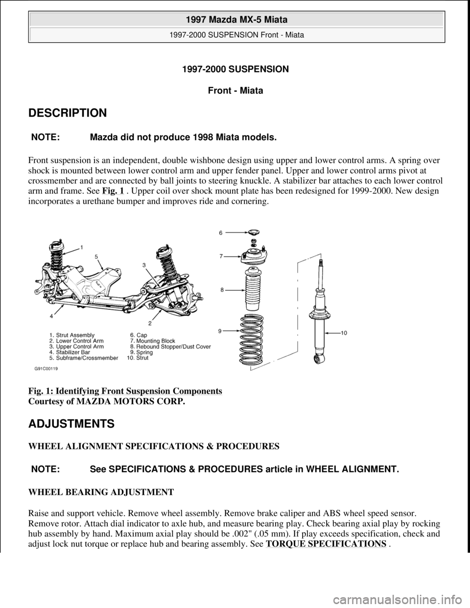
Front suspension is an independent, double wishbone design using upper and lower control arms. A spring over
shock is mounted between lower control arm and upper fender panel. Upper and lower control arms pivot at
crossmember and are connected by ball joints to steering knuckle. A stabilizer bar attaches to each lower control
arm and frame. See Fig. 1
. Upper coil over shock mount plate has been redesigned for 1999-2000. New design
incorporates a urethane bumper and improves ride and cornering.
Fig. 1: Identifying Front Suspension Components
Courtesy of MAZDA MOTORS CORP.
ADJUSTMENTS
WHEEL ALIGNMENT SPECIFICATIONS & PROCEDURES
WHEEL BEARING ADJUSTMENT
Raise and support vehicle. Remove wheel assembly. Remove brake caliper and ABS wheel speed sensor.
Remove rotor. Attach dial indicator to axle hub, and measure bearing play. Check bearing axial play by rocking
hub assembly by hand. Maximum axial play should be .002" (.05 mm). If play exceeds specification, check and
adjust lock nut torque or replace hub and bearing assembly. See TORQUE SPECIFICATIONS
. NOTE: Mazda did not produce 1998 Miata models.
NOTE: See SPECIFICATIONS & PROCEDURES article in WHEEL ALIGNMENT.
1997 Mazda MX-5 Miata
1997-2000 SUSPENSION Front - Miata
1997 Mazda MX-5 Miata
1997-2000 SUSPENSION Front - Miata
Microsoft
Sunday, July 05, 2009 1:38:08 PMPage 1 © 2005 Mitchell Repair Information Company, LLC.
Microsoft
Sunday, July 05, 2009 1:38:12 PMPage 1 © 2005 Mitchell Repair Information Company, LLC.
Page 289 of 514
INSPECTION
BALL JOINT CHECKING
Lower Ball Joint
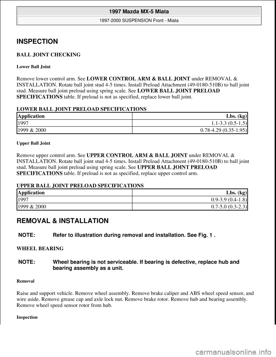
Remove lower control arm. See LOWER CONTROL ARM & BALL JOINT under REMOVAL &
INSTALLATION. Rotate ball joint stud 4-5 times. Install Preload Attachment (49-0180-510B) to ball joint
stud. Measure ball joint preload using spring scale. See LOWER BALL JOINT PRELOAD
SPECIFICATIONS table. If preload is not as specified, replace lower ball joint.
LOWER BALL JOINT PRELOAD SPECIFICATIONS
Upper Ball Joint
Remove upper control arm. See UPPER CONTROL ARM & BALL JOINT under REMOVAL &
INSTALLATION. Rotate ball joint stud 4-5 times. Install Preload Attachment (49-0180-510B) to ball joint
stud. Measure ball joint preload using spring scale. See UPPER BALL JOINT PRELOAD
SPECIFICATIONS table. If preload is not as specified, replace upper control arm.
UPPER BALL JOINT PRELOAD SPECIFICATIONS
REMOVAL & INSTALLATION
WHEEL BEARING
Removal
Raise and support vehicle. Remove wheel assembly. Remove brake caliper and ABS wheel speed sensor, and
wire aside. Remove grease cap and axle lock nut. Remove brake rotor. Remove hub and bearing assembly.
Remove wheel speed sensor rotor from hub.
Inspection
ApplicationLbs. (kg)
19971.1-3.3 (0.5-1.5)
1999 & 20000.78-4.29 (0.35-1.95)
ApplicationLbs. (kg)
19970.9-3.9 (0.4-1.8)
1999 & 20000.7-5.0 (0.3-2.3)
NOTE: Refer to illustration during removal and installation. See Fig. 1
.
NOTE: Wheel bearing is not serviceable. If bearing is defective, replace hub and
bearing assembly as a unit.
1997 Mazda MX-5 Miata
1997-2000 SUSPENSION Front - Miata
Microsoft
Sunday, July 05, 2009 1:38:08 PMPage 2 © 2005 Mitchell Repair Information Company, LLC.
Page 368 of 514

1997, 1999-2000 SUSPENSION
Rear - Miata
DESCRIPTION
Rear suspension consists of spring over shock, crossmember, upper and lower arms, and stabilizer bar with
control link. Upper and lower arms attach to crossmember and knuckle. A stabilizer bar with control link is
mounted to lower arm and crossmember. Rear wheel alignment is adjusted by turning adjusting cams on lower
arm. Upper coil over shock mount plate has been redesigned for 1999-2000. New design incorporates a
urethane bumper and improves ride and cornering.
ADJUSTMENTS & INSPECTION
WHEEL ALIGNMENT SPECIFICATIONS & PROCEDURES
WHEEL BEARING ADJUSTMENT
Raise and support vehicle. Remove rear wheel assembly. Remove caliper assembly and ABS wheel speed
sensor. Remove brake rotor. Attach dial indicator to axle hub and measure bearing play. Check bearing axial
play by rocking hub assembly by hand. Maximum bearing play is .002" (.05 mm). If play exceeds specification,
check drive axle lock nut torque or replace wheel bearing. See TORQUE SPECIFICATIONS
.
REMOVAL & INSTALLATION
WHEEL BEARING
Removal
1. Raise and support vehicle. Remove rear wheel assembly. Remove drive axle lock nut. Remove brake
caliper assembly and ABS wheel speed sensor, and wire aside. Remove screws and rotor. Remove ABS
speed sensor bracket. Remove knuckle assembly from upper and lower arms.
2. Using Handle (49-G030-102), Installer (49-G030-727) and Puller (49-F026-103), remove hub from
knuckle. Remove snap ring from knuckle. Using handle, installer and Puller (49-0636-145), remove
wheel bearing inner race from hub. Remove wheel bearing outer race from knuckle using Handle (49-
G030-797), Puller (49-F026-103) and Adapter (49-F027-005).
Inspection
Check wheel hub and knuckle for cracks and damage. Check dust cover for deformation. Check bearing for
excessive wear or seizure. Replace components as necessary.
Installation
NOTE: See SPECIFICATIONS & PROCEDURES article in WHEEL ALIGNMENT.
1997 Mazda MX-5 Miata
1997, 1999-2000 SUSPENSION Rear - Miata
1997 Mazda MX-5 Miata
1997, 1999-2000 SUSPENSION Rear - Miata
Microsoft
Sunday, July 05, 2009 1:38:49 PMPage 1 © 2005 Mitchell Repair Information Company, LLC.
Microsoft
Sunday, July 05, 2009 1:38:53 PMPage 1 © 2005 Mitchell Repair Information Company, LLC.