wheel torque MAZDA MIATA 1997 Factory User Guide
[x] Cancel search | Manufacturer: MAZDA, Model Year: 1997, Model line: MIATA, Model: MAZDA MIATA 1997Pages: 514, PDF Size: 17.89 MB
Page 171 of 514

Fig. 11: Exploded View Of Clutch Release Cylinder (Miata)
Courtesy of MAZDA MOTORS CORP.
TORQUE SPECIFICATIONS
TORQUE SPECIFICATIONS NOTE: Use exploded view of clutch release cylinder for overhaul procedure. See Fig.
11 .
ApplicationFt. Lbs. (N.m)
B2300, B2500, B3000 & B4000
Clutch Cover Bolts (1) 17-24 (23-32)
Crossmember Nuts39-53 (53-72)
Drive Shaft Bolts65-87 (88-119)
Flywheel-To-Crankshaft Nuts54-67 (73-91)
Gearshift Lever Bolt20-30 (27-40)
Starter Mounting Bolts17-20 (23-27)
Transfer Case Bolts (4WD) (2) 35-46 (47-62)
Transmission-To-Engine Block Bolts37-50 (50-68)
Miata
Clutch Cover Bolts (1) 13-19 (18-26)
Drive Shaft Nuts37-43 (50-58)
Flywheel-To-Crankshaft Bolts71-76 (96-103)
PPF-To-Differential Mounting Spacer Bolt (Short)27-38 (37-51)
PPF-To-Differential Side Mounting Bolts (Long)77-91 (104-123)
PPF-To-PPF Bracket Bolt27-40 (37-54)
1997 Mazda MX-5 Miata
CLUTCH 1997-98 CLUTCHES Mazda - RWD
Microsoft
Sunday, July 05, 2009 1:36:47 PMPage 15 © 2005 Mitchell Repair Information Company, LLC.
Page 180 of 514

Fig. 4: Installing Oil Seal (MPV)
Courtesy of MAZDA MOTORS CORP.
9. Install the companion flange and tighten the locknut to get the starting torque measured in step 4 .
10. Install the drive shaft. Tighten bolts to specfiication. See TORQUE SPECIFICATIONS
. Add
differential oil to the specified level. SeeFLUID TYPE
.
REAR AXLE SHAFTS & BEARINGS
Removal (MPV)
1. Raise and support vehicle. Remove rear wheel and tire assembly. Remove brake caliper and support
aside. Remove brake disc plate. See Fig. 5
. Using dial indicator, measure axle bearing play. Replace axle
bearing if play exceeds .023" (.57 mm).
2. Remove hold pin from parking brake shoe assembly and remove parking brake shoe assembly.
Disconnect parking brake cable. Using Flare Nut Wrench (49-0259-770B), disconnect brake pipe. Plug
brake pipe openings.
3. Remove rear axle shaft assembly-to-axle shaft housing retaining nuts. Using Puller (49-0223-630B) and
Attachment (49-8501-631A), remove rear axle shaft, backin
g plate and dust cover as an assembly from
1997 Mazda MX-5 Miata
1997-98 DRIVE AXLES Differentials & Drive Axles - MPV & MX-5 Miata
Microsoft
Sunday, July 05, 2009 1:52:42 PMPage 6 © 2005 Mitchell Repair Information Company, LLC.
Page 181 of 514
axle shaft housing. Remove axle oil seal. See Fig. 5. With axle shaft removed, remove retaining ring.
Remove ABS sensor rotor.
4. To remove bearing collar, grind collar until a section about .02" (.50 mm) remains. Using chisel, cut
remaining bearing collar from axle shaft. Using Puller (49-S121-520A), remove axle bearing from axle
shaft. Remove dust shield and backing plate.
5. Using dial indicator and "V" blocks, check axle shaft for straightness. Maximum axle shaft runout
is .059" (1.50 mm). Also check axle shaft splines for wear and damage. Use a press to replace wheel studs
as necessary. DO NOT reuse wheel studs if removed.
Installation
To install, reverse removal procedure. Lubricate oil seal lip before replacement. Use Attachment (49-1011-748)
and a press to install axle bearing onto axle shaft. DO NOT lubricate bearing collar before replacement. Use
Attachment (49-1011-748) and a press to install NEW bearing collar. If press fit of collar requires less than 2.7
tons (2699 k
g) to install, replace axle shaft. Tighten nuts to specification. See TORQUE SPECIFICATIONS.
1997 Mazda MX-5 Miata
1997-98 DRIVE AXLES Differentials & Drive Axles - MPV & MX-5 Miata
Microsoft
Sunday, July 05, 2009 1:52:42 PMPage 7 © 2005 Mitchell Repair Information Company, LLC.
Page 183 of 514

Fig. 5: Exploded View Of Rear Axle Shaft (MPV)
Courtesy of MAZDA MOTORS CORP.
DIFFERENTIAL ASSEMBLY
Removal (Front MPV 4WD)
1. Raise and support vehicle. Remove engine skid plate. See Fig. 6 . Drain front differential fluid. Remove
tie rod ends and lower control arms. Remove front axle shafts. See AXLE SHAFTS
- FRONT article.
2. Mark drive shaft and differential carrier flanges for reassembly reference, and remove drive shaft from
differential carrier. See Fig. 6
. Disconnect Automatic Free Wheel (AFW) vacuum hoses and electrical
connector.
3. Place floor jack under differential assembly. Remove differential-to-chassis mounting bolts and AFW
extension housing mounting nuts. Remove differential and AFW extension housing from vehicle.
Remove AFW assembly from left side of differential housing. Pull drive coupler from carrier. Remove
differential carrier-to-housing bolts. Remove differential carrier.
Installation
To install, reverse removal procedure. Apply sealant to carrier mating flange. Align marks made during
removal. Refill differential with lubricant. Tighten all nuts and bolts to specification. See TORQUE
SPECIFICATIONS.
1997 Mazda MX-5 Miata
1997-98 DRIVE AXLES Differentials & Drive Axles - MPV & MX-5 Miata
Microsoft
Sunday, July 05, 2009 1:52:42 PMPage 9 © 2005 Mitchell Repair Information Company, LLC.
Page 185 of 514

See REAR AXLE SHAFTS & BEARINGS.
2. Remove ABS wheel speed sensor. Mark drive shaft and differential carrier flanges for reassembly
reference and remove drive shaft from differential carrier. Remove differential carrier-to-housing bolts.
Remove differential carrier.
Installation
To install, reverse removal procedure. Apply sealant to carrier mating flange. Align marks made during
removal. Refill differential with lubricant. Tighten all nuts and bolts to specification. See TORQUE
SPECIFICATIONS .
Removal (Miata)
1. Raise and support vehicle. Remove wheel and tire assembly. Drain differential. Remove differential
mounting pipe. Remove exhaust pipe. Mark drive shaft and differential carrier flanges for reassembly
reference and remove drive shaft from differential carrier. See Fig. 7
. Disconnect speedometer cable
from transmission. Notin
g locations, disconnect wiring harness from Power Plant Frame (PPF).
1997 Mazda MX-5 Miata
1997-98 DRIVE AXLES Differentials & Drive Axles - MPV & MX-5 Miata
Microsoft
Sunday, July 05, 2009 1:52:42 PMPage 11 © 2005 Mitchell Repair Information Company, LLC.
Page 197 of 514

TORQUE SPECIFICATIONS (MPV)
Power Plant Frame-To-Differential
Side Mounting Bolts (Long)77-91 (104-123)
Spacer Bolt (Short)27-38 (37-52)
Power Plant Frame-To-Transmission Side Mounting Bolts (Long)77-91 (104-123)
Ring Gear Retaining Bolts51-61 (69-83)
Wheel Lug Nuts65-87 (88-118)
ApplicationFt. Lbs. (N.m)
AFW Extension Housing Mount Nut (4WD)49-72 (66-98)
Brake Pipe Union10-16 (14-22)
Differential Carrier Bearings Cap Bolts Front Differential27-38 (37-52)
Differential Carrier Bearings Cap Bolts Rear Differential54-78 (73-106)
Differential Carrier Bearings Lock Plate Bolt13-19 (18-26)
Differential Carrier-To-Housing Nuts/Bolts17-19 (23-26)
Differential-To-Chassis Mount Nuts (4WD)49-72 (66-98)
Drive Pinion Lock Nut94-210 (127-284)
Drive Shaft Companion Flange Nuts37-43 (50-58)
Filler Plug29-40 (39-54)
Lower Ball Joint-To-Control Arm Bolts (4WD)75-101 (102-137)
Lower Ball Joint-To-Control Arm Nut (4WD)94-127 (127-172)
Rear ABS Wheel Speed Sensor Bolt12-16 (16-22)
Rear Axle Shaft Assembly-To-Axle Shaft Housing Retaining Nuts40-49 (54-66)
Rear Brake Caliper Bolts37-43 (50-58)
Ring Gear Retaining Bolts51-61 (69-83)
Skid Plate Bolts (4WD)12-17 (16-23)
Tie Rod End Nut (4WD)43-58 (58-78)
Wheel Lug Nuts65-87 (88-118)
1997 Mazda MX-5 Miata
1997-98 DRIVE AXLES Differentials & Drive Axles - MPV & MX-5 Miata
Microsoft
Sunday, July 05, 2009 1:52:42 PMPage 23 © 2005 Mitchell Repair Information Company, LLC.
Page 218 of 514

wheel puller. Pry out seal.
Installation
1. Apply light oil coat to seal lip. Using a hammer and seal installer, tap seal into oil pump body until it is
flush with edge of pump body. DO NOT bottom seal in pump body. Align keyway slots, and install
crankshaft sprocket and Woodruff key with tapered side toward oil pump body. Install crankshaft
sprocket bolt.
2. Using Crankshaft Lock Tool (49-D011-102), lock crankshaft sprocket into position. Tighten lock bolt to
specification. See TORQUE SPECIFICATIONS
.
3. Install timing belt. See TIMING BELT
under REMOVAL & INSTALLATION. Install timing belt
covers, pulleys and drive belts. Reconnect negative battery cable and ensure timing is correct.
TIMING BELT
Removal (Miata)
1. Disconnect negative battery cable. Drain cooling system. Remove radiator hose and by-pass hoses from
thermostat housing. Remove air cleaner intake duct assembly from between throttle body and air cleaner
filter housing.
2. Remove drive belts and water pump pulley. Align crankshaft pulley timing mark with cylinder No. 1 at
TDC of compression stroke. Hold crankshaft pulley stationary. Remove crankshaft pulley bolts and
pulley. Remove crankshaft pulley hub bolt and hub.
3. Remove cylinder head cover. Remove upper, center and lower timing belt cover. If timing belt is to be
reused, mark timing belt rotation direction. Ensure timing marks on camshaft sprockets are aligned. See
Fig. 8
. Loosen timing belt tensioner lock bolt, and move tensioner away from belt with spring fully
expanded. Remove timing belt.
Removal (Protege)
1. Disconnect negative battery cable. Raise and support vehicle. Remove right front wheel. Remove right
side cover and undercover.
2. Remove drive belts and water pump pulley. Align crankshaft pulley timing mark with cylinder No. 1 at
TDC of compression stroke. Hold crankshaft stationary. Remove crankshaft pulley bolts and pulley.
Remove crankshaft pulley hub bolt and hub.
3. Remove cylinder head cover. Remove upper, center and lower timing belt cover. If timing belt is to be
reused, mark timing belt rotation direction. Ensure timing marks on camshaft sprockets are aligned. See
Fig. 8
. Loosen timing belt tensioner lock bolt, and move tensioner away from belt with spring fully
expanded. Remove timin
g belt. NOTE: For 1997-98 vehicles, the manufacturer recommends the belt be replaced at
60,000 mile intervals for vehicles sold outside of California and Massachusetts.
For vehicles sold in California and Massachusetts, inspect timing belt at 60,000
and 90,000 miles, and replace timing belt at 105,000 miles.
1997 Mazda MX-5 Miata
1997-98 ENGINES 1.8L 4-Cylinder
Microsoft
Sunday, July 05, 2009 1:55:15 PMPage 12 © 2005 Mitchell Repair Information Company, LLC.
Page 239 of 514

OIL PUMP
Removal & Disassembly
1. Disconnect negative battery cable. Remove dipstick, tube and "O" ring. Drain engine oil and coolant.
Remove drive belts, crankshaft and water pump pulleys. Remove generator, A/C compressor and
mounting bracket. Without disconnecting A/C hoses, secure A/C compressor away from engine. Remove
timing belt and related components. See TIMING BELT
under REMOVAL & INSTALLATION.
2. Hold crankshaft sprocket in place and remove crankshaft sprocket bolt. Remove crankshaft sprocket
using steering wheel puller. Leave crankshaft Woodruff key in place.
3. Remove oil pan and oil pump pick-up tube. See OIL PAN
under REMOVAL & INSTALLATION.
Remove oil pump housing assembly. Using a screwdriver protected with a rag, drive oil seal out from
inside of oil pump housing assembly.
4. Remove pump cover screws (use a manual impact screwdriver, if necessary). See Fig. 22
. Remove pump
cover. Note location of alignment marks on inner and outer rotors. Remove inner and outer rotors. To
remove pressure relief valve, remove spring seat, pressure spring and control plunger.
Inspection
Replace pressure relief valve spring if length is not as specified. See OIL PUMP SPECIFICATIONS. Ensure
plunger slides freely in bore. Replace oil pump housing assembly if clearances are not as specified. See OIL
PUMP SPECIFICATIONS .
Reassembly & Installation
1. Apply oil to friction surfaces. Install inner and outer rotors with marks aligned. See Fig. 23 . Install
pressure relief valve components. Apply oil to lip of NEW oil seal. Press oil seal into bore until even with
face of oil pump housing assembly.
2. Install pump cover. Tighten screws to 53-78 INCH lbs. (6-9 N.m). To complete installation, reverse
removal procedure. Tighten bolts to specification. See TORQUE SPECIFICATIONS
.
OIL PUMP SPECIFICATIONS
ApplicationW/O Filter Qts. (L)W/Filter Qts. (L)
Miata & Protege3.8 (3.6)4.0 (3.8)
ApplicationMaximum Clearance In. (mm)
Maximum Rotor Tip Clearance (1) .0079 (.20)
Maximum Rotor-To-Pump Body Clearance (2) .0079 (.20)
Maximum Rotor Side Clearance (3) .0055 (.14)
Pressure Relief Spring Free Length1.809 (45.94)
(1)See Fig. 23 .
(2)Insert feeler gauge between outer rotor and pump body.
Place straightedge across pump body and check clearance between straightedge and both rotors.
1997 Mazda MX-5 Miata
1997-98 ENGINES 1.8L 4-Cylinder
Microsoft
Sunday, July 05, 2009 1:55:15 PMPage 33 © 2005 Mitchell Repair Information Company, LLC.
Page 288 of 514
1997-2000 SUSPENSION
Front - Miata
DESCRIPTION
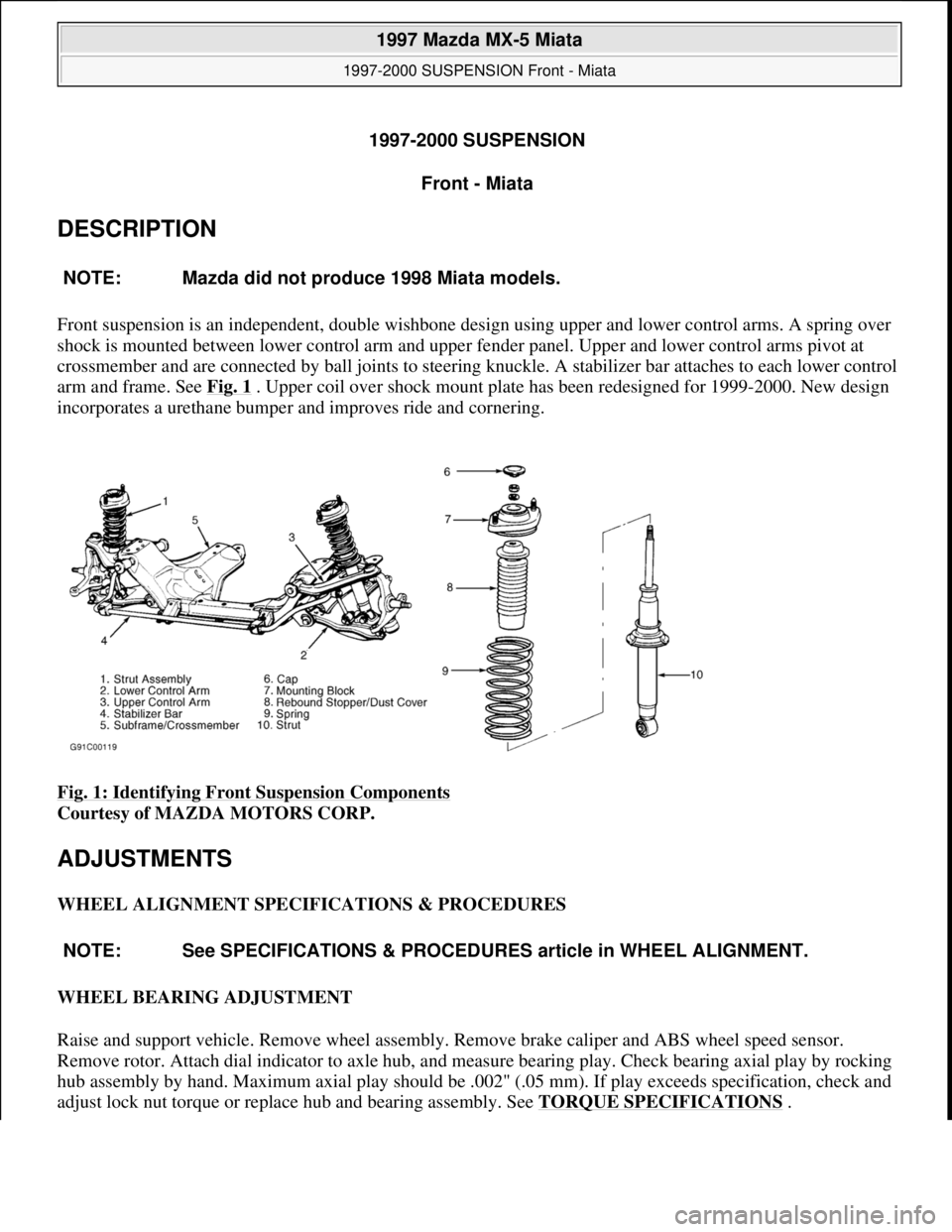
Front suspension is an independent, double wishbone design using upper and lower control arms. A spring over
shock is mounted between lower control arm and upper fender panel. Upper and lower control arms pivot at
crossmember and are connected by ball joints to steering knuckle. A stabilizer bar attaches to each lower control
arm and frame. See Fig. 1
. Upper coil over shock mount plate has been redesigned for 1999-2000. New design
incorporates a urethane bumper and improves ride and cornering.
Fig. 1: Identifying Front Suspension Components
Courtesy of MAZDA MOTORS CORP.
ADJUSTMENTS
WHEEL ALIGNMENT SPECIFICATIONS & PROCEDURES
WHEEL BEARING ADJUSTMENT
Raise and support vehicle. Remove wheel assembly. Remove brake caliper and ABS wheel speed sensor.
Remove rotor. Attach dial indicator to axle hub, and measure bearing play. Check bearing axial play by rocking
hub assembly by hand. Maximum axial play should be .002" (.05 mm). If play exceeds specification, check and
adjust lock nut torque or replace hub and bearing assembly. See TORQUE SPECIFICATIONS
. NOTE: Mazda did not produce 1998 Miata models.
NOTE: See SPECIFICATIONS & PROCEDURES article in WHEEL ALIGNMENT.
1997 Mazda MX-5 Miata
1997-2000 SUSPENSION Front - Miata
1997 Mazda MX-5 Miata
1997-2000 SUSPENSION Front - Miata
Microsoft
Sunday, July 05, 2009 1:38:08 PMPage 1 © 2005 Mitchell Repair Information Company, LLC.
Microsoft
Sunday, July 05, 2009 1:38:12 PMPage 1 © 2005 Mitchell Repair Information Company, LLC.
Page 290 of 514
Check for damage, excessive wear and signs of bearing seizure. Inspect steering knuckle and hub for cracks,
scoring and rust. Check for damaged dust cover and poor fit with steering knuckle. Replace components as
necessary.
Installation
To install, reverse removal procedure. Adjust wheel bearing preload. See WHEEL BEARING
ADJUSTMENT under ADJUSTMENTS. Stake axle nut.
LOWER CONTROL ARM & BALL JOINT
Removal
1. Raise and support vehicle. Remove wheel assembly. Remove engine splash shield (if equipped). Separate
tie rod end from steering knuckle (as necessary). Remove stabilizer bar from lower control arm.
2. Remove shock lower mounting bolt and separate lower shock from lower control arm. Remove lower
control arm ball joint cotter pin and nut. Separate lower control arm ball joint stud from knuckle using
Puller (49 T028 3A0). Remove lower control arm pivot bolts and remove lower control arm.
Inspection
Check lower control arm for damage or cracks. Check bushings for deterioration and excessive wear. Check
ball joint for excessive wear. Examine dust boot for damage. Replace components as necessary.
Bushing Replacement
Cut or press old bushing from control arm. Coat NEW bushing with paraffin-based oil. Press new bushing into
control arm.
Installation (All Models)
To install, reverse removal procedure. Tighten lower control arm-to-frame bolts to specification with vehicle
resting on ground and suspension unloaded. See TORQUE SPECIFICATIONS
.
UPPER CONTROL ARM & BALL JOINT
Removal
Raise and support vehicle. Remove wheel assembly. Remove engine splash shield. Remove wheel speed sensor
harness band. Remove shock lower mounting bolt, and separate lower shock from lower control arm. Remove
upper control arm ball joint cotter pin and nut. Separate upper control arm ball joint stud from knuckle using
Puller (49-0118-850C). Remove upper control arm pivot bolts and remove upper control arm.
Inspection
Check upper control arm for damage or cracks. Check bushings for deterioration and excessive wear. Check
ball joint for excessive wear. Examine dust boot for damage. Replace components as necessary.
1997 Mazda MX-5 Miata
1997-2000 SUSPENSION Front - Miata
Microsoft
Sunday, July 05, 2009 1:38:08 PMPage 3 © 2005 Mitchell Repair Information Company, LLC.