wheel torque MAZDA MIATA 1997 Factory Owner's Manual
[x] Cancel search | Manufacturer: MAZDA, Model Year: 1997, Model line: MIATA, Model: MAZDA MIATA 1997Pages: 514, PDF Size: 17.89 MB
Page 291 of 514
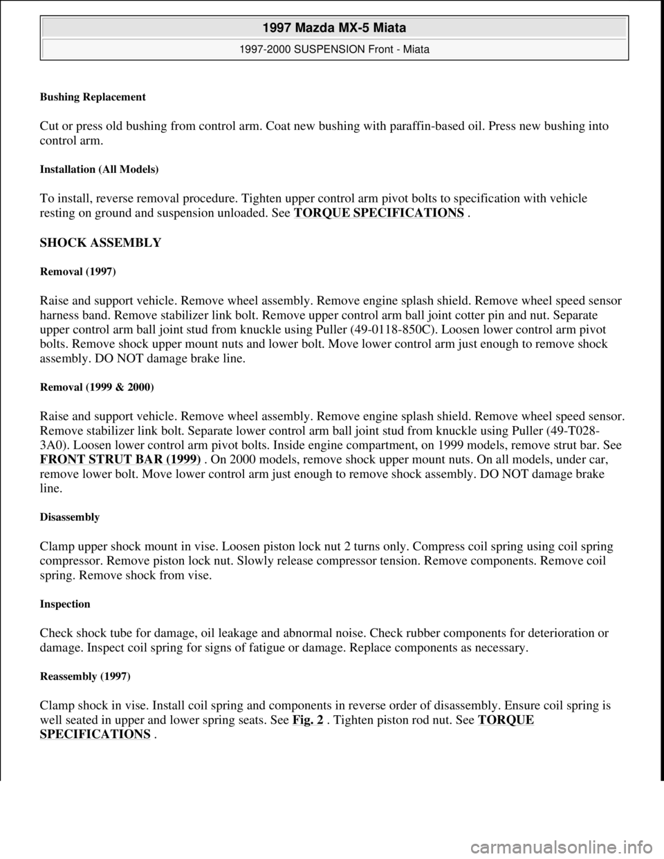
Bushing Replacement
Cut or press old bushing from control arm. Coat new bushing with paraffin-based oil. Press new bushing into
control arm.
Installation (All Models)
To install, reverse removal procedure. Tighten upper control arm pivot bolts to specification with vehicle
resting on ground and suspension unloaded. See TORQUE SPECIFICATIONS
.
SHOCK ASSEMBLY
Removal (1997)
Raise and support vehicle. Remove wheel assembly. Remove engine splash shield. Remove wheel speed sensor
harness band. Remove stabilizer link bolt. Remove upper control arm ball joint cotter pin and nut. Separate
upper control arm ball joint stud from knuckle using Puller (49-0118-850C). Loosen lower control arm pivot
bolts. Remove shock upper mount nuts and lower bolt. Move lower control arm just enough to remove shock
assembly. DO NOT damage brake line.
Removal (1999 & 2000)
Raise and support vehicle. Remove wheel assembly. Remove engine splash shield. Remove wheel speed sensor.
Remove stabilizer link bolt. Separate lower control arm ball joint stud from knuckle using Puller (49-T028-
3A0). Loosen lower control arm pivot bolts. Inside engine compartment, on 1999 models, remove strut bar. See
FRONT STRUT BAR (1999)
. On 2000 models, remove shock upper mount nuts. On all models, under car,
remove lower bolt. Move lower control arm just enough to remove shock assembly. DO NOT damage brake
line.
Disassembly
Clamp upper shock mount in vise. Loosen piston lock nut 2 turns only. Compress coil spring using coil spring
compressor. Remove piston lock nut. Slowly release compressor tension. Remove components. Remove coil
spring. Remove shock from vise.
Inspection
Check shock tube for damage, oil leakage and abnormal noise. Check rubber components for deterioration or
damage. Inspect coil spring for signs of fatigue or damage. Replace components as necessary.
Reassembly (1997)
Clamp shock in vise. Install coil spring and components in reverse order of disassembly. Ensure coil spring is
well seated in upper and lower spring seats. See Fig. 2
. Tighten piston rod nut. See TORQUE
SPECIFICATIONS .
1997 Mazda MX-5 Miata
1997-2000 SUSPENSION Front - Miata
Microsoft
Sunday, July 05, 2009 1:38:08 PMPage 4 © 2005 Mitchell Repair Information Company, LLC.
Page 294 of 514
Installation
To install, reverse removal procedure. Fully tighten all bolts with vehicle resting on ground and suspension
unloaded. See TORQUE SPECIFICATIONS
. Check front wheel alignment. See SPECIFICATIONS &
PROCEDURES article in WHEEL ALIGNMENT.
STABILIZER BAR
Removal & Installation
Raise and support vehicle. Remove engine splash shield. Remove frame brackets and bushings. Remove
stabilizer control links. Align bushing with installation mark on stabilizer. Reverse removable procedure for
installation. See TORQUE SPECIFICATIONS
.
FRONT STRUT BAR (1999)
Removal & Installation
1. To remove strut bar located in engine compartment mounted on top of shock towers, loosen lock nuts on
joint bolt and loosen joint bolt. Remove nut, washer and bolt retaining strut bar to strut plate. Remove
strut bar from vehicle.
2. To install, reverse removal procedure. Rotate joint bolt counterclockwise to 3.5-5.2 INCH lbs. (.4-.6 N.m)
to set tension. Tighten lock nuts to 87-121 INCH lbs. (10-14 N.m). Tighten strut bar-to-strut plate nut.
See TORQUE SPECIFICATIONS
.
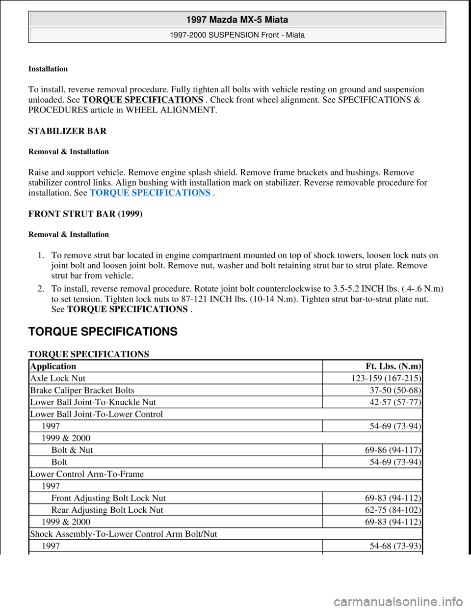
TORQUE SPECIFICATIONS
TORQUE SPECIFICATIONS
ApplicationFt. Lbs. (N.m)
Axle Lock Nut123-159 (167-215)
Brake Caliper Bracket Bolts37-50 (50-68)
Lower Ball Joint-To-Knuckle Nut42-57 (57-77)
Lower Ball Joint-To-Lower Control
199754-69 (73-94)
1999 & 2000
Bolt & Nut69-86 (94-117)
Bolt54-69 (73-94)
Lower Control Arm-To-Frame
1997
Front Adjusting Bolt Lock Nut69-83 (94-112)
Rear Adjusting Bolt Lock Nut62-75 (84-102)
1999 & 200069-83 (94-112)
Shock Assembly-To-Lower Control Arm Bolt/Nut
199754-68 (73-93)
1997 Mazda MX-5 Miata
1997-2000 SUSPENSION Front - Miata
Microsoft
Sunday, July 05, 2009 1:38:08 PMPage 7 © 2005 Mitchell Repair Information Company, LLC.
Page 318 of 514

TORQUE SPECIFICATIONS
WIRING DIAGRAM
ApplicationFt. Lbs. (N.m)
Compressor Bracket-To-Engine Bolt28-38 (38-51)
Compressor-To-Compressor Bracket Bolt11-15 (15-21)
Refrigerant Pipe Fittings
Condenser Inlet11-18 (15-24)
Evaporator Outlet15-21 (20-29)
INCH Lbs. (N.m)
Evaporator Unit Nut71-97 (8-11)
Refrigerant Pipe Fittings
Compressor Inlet & Outlet89-132 (10-15)
Evaporator Inlet89-168 (10-19)
Receiver-Drier Inlet & Outlet89-168 (10-19)
Steering Wheel Nut79-121 (9-14)
1997 Mazda MX-5 Miata
A/C-HEATER SYSTEM - MANUAL 1997 Manual A/C-Heater System
Microsoft
Sunday, July 05, 2009 1:41:48 PMPage 9 © 2005 Mitchell Repair Information Company, LLC.
Page 338 of 514

LUBRICATION
FLUID CAPACITY
POWER STEERING FLUID CAPACITY
FLUID TYPE
Dexron-II or Mazda M-III fluid is recommended for all models.
FLUID LEVEL CHECK
Check fluid level on oil pump dipstick (if equipped) or reservoir. Fluid should be between marks on level gauge
dipstick (if equipped) or reservoir. If fluid level is low, fill as necessary. Recheck fluid level. DO NOT overfill.
HYDRAULIC SYSTEM BLEEDING
1. Raise and support front of vehicle. With ignition off, turn steering wheel from lock to lock several times.
Check fluid level. Add fluid as necessary. Repeat procedure until fluid level no longer decreases.
2. Start engine and operate at idle. Turn steering wheel from lock to lock 5 times. Check fluid level. Add
fluid as necessary. Continue procedure until fluid is clear of air bubbles and does not decrease in level.
ADJUSTMENTS
PINION PRELOAD
Miata & Protege
1. Ensure steering rack is in center position. Using Protractor (49-D032-316 ) and a torque wrench, tighten
adjusting cover to 43 INCH lbs. (4.9 N.m), then loosen adjusting cover. See Fig. 2
. Repeat loosening and
ti
ghtening procedure 3 times. After tightening adjusting cover the third time, loosen adjusting cover 25
ApplicationQts. (L)
Miata & Protege.85 (.80)
MPV.95 (.90)
MX-3
4-Cylinder.85 (.80)
V61.27 (1.20)
Millenia, MX-6 & 6261.32 (1.25)
RX71.01 (.96)
9291.80 (1.70)
NOTE: Pinion preload should be checked when steering gear assembly has been
disassembled or overhauled. Check preload after steering gear assembly has
been reassembled, but tie rods have not yet been installed.
1997 Mazda MX-5 Miata
STEERING SYSTEM - POWER RACK & PINION 1997 STEERING Mazda Power Rack & Pinion
Microsoft
Sunday, July 05, 2009 1:39:26 PMPage 3 © 2005 Mitchell Repair Information Company, LLC.
Page 345 of 514

frame mounting bolts. Remove steering gear and linkage from vehicle. On MPV, remove steering gear
bracket-to-frame mounting bolts. Remove steering gear and linkage with steering bracket from vehicle.
Remove 4 steering gear-to-bracket bolts and separate gear from bracket.
4. On all models, to install, reverse removal procedure. Tighten bolts to specification. See TORQUE
SPECIFICATIONS table. On MPV, tighten steering gear-to-bracket bolts in sequence: left front, right
front, left rear, right rear. On all models, fill and bleed power steering system. Check and adjust front
wheel alignment. See SPECIFICATIONS & PROCEDURES article in WHEEL ALIGNMENT.
Removal & Installation (Millenia)
1. Disconnect negative battery cable. Support engine using Engine Support (49-G017-5A0 ). Raise and
support front of vehicle. Remove front wheel assemblies. Remove cotter pins and castle nuts from tie rod
ends.
2. Using Puller Set (49-T028-3A0 ), separate tie rod ends from steering knuckles. Remove transverse
member bolts and remove transverse member. See Fig. 6
Disconnect pressure and return line connections
from steering gear. Remove intermediate shaft pinch bolt.
3. Reference mark lower steering column-to-intermediate shaft. Remove engine mount member. Remove
No. 1 engine mount bolts. Remove upper lateral link bolt and separate upper lateral link from
crossmember. Remove lower control arm-to-crossmember mounting bolt and gusset. Separate lower
control arm from crossmember.
4. Remove stabilizer link-to-lower control arm nut. Separate stabilizer link from lower control arm. Using a
jack, support front suspension crossmember. Remove crossmember retaining nuts. Carefully lower
crossmember. Disconnect stabilizer link from stabilizer bar. Remove stabilizer bar brackets, bushings and
stabilizer bar. Remove steering gear mounting nuts. Remove steering gear assembly.
5. To install, reverse removal procedure. Tighten bolts to specification. See TORQUE SPECIFICATIONS
table. Tighten steering gear mounting nuts in sequence: right front, left rear, right rear, left front. Fill and
bleed power steering system. Check and adjust front wheel alignment. See SPECIFICATIONS &
PROCEDURES article in WHEEL ALIGNMENT.
1997 Mazda MX-5 Miata
STEERING SYSTEM - POWER RACK & PINION 1997 STEERING Mazda Power Rack & Pinion
Microsoft
Sunday, July 05, 2009 1:39:26 PMPage 10 © 2005 Mitchell Repair Information Company, LLC.
Page 347 of 514
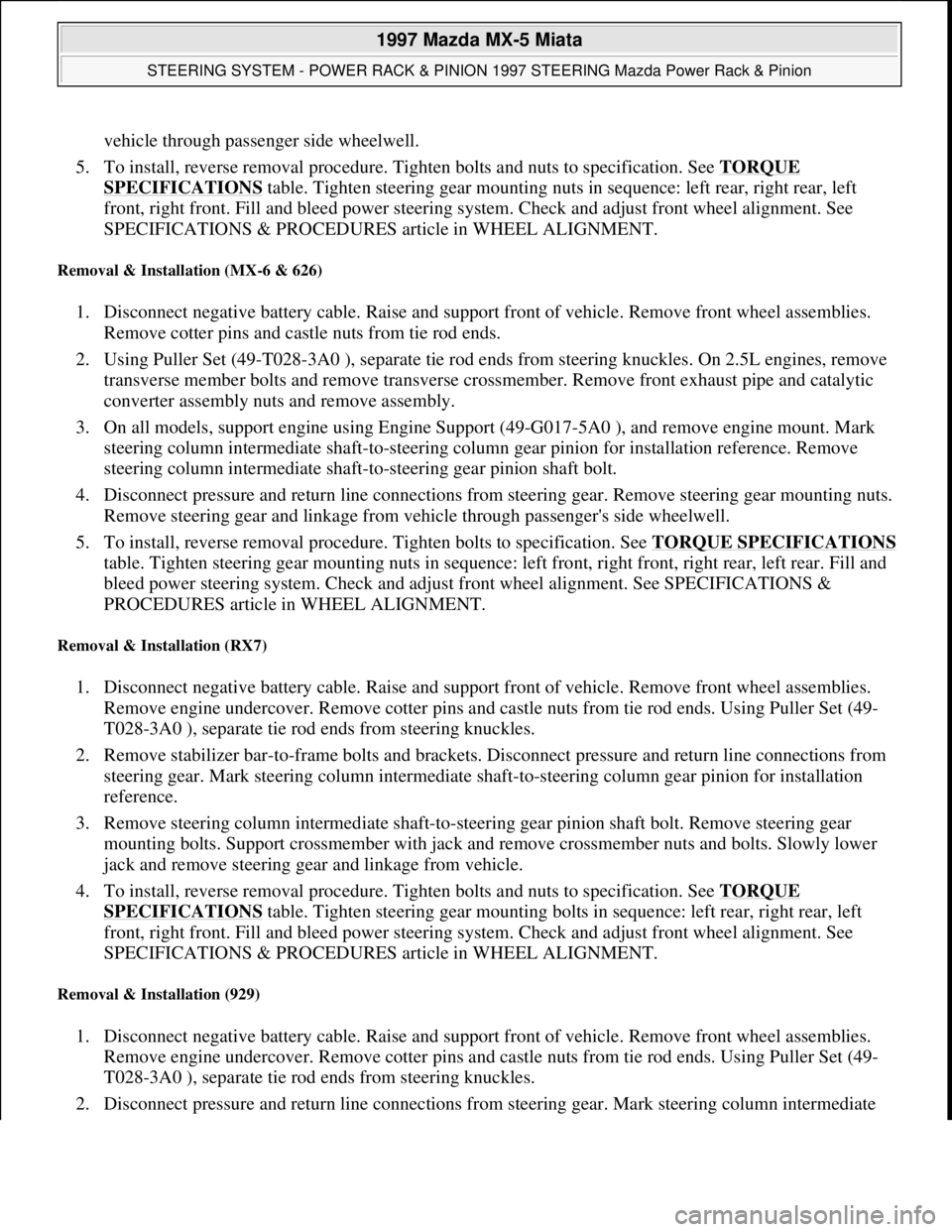
vehicle through passenger side wheelwell.
5. To install, reverse removal procedure. Tighten bolts and nuts to specification. See TORQUE
SPECIFICATIONS table. Tighten steering gear mounting nuts in sequence: left rear, right rear, left
front, right front. Fill and bleed power steering system. Check and adjust front wheel alignment. See
SPECIFICATIONS & PROCEDURES article in WHEEL ALIGNMENT.
Removal & Installation (MX-6 & 626)
1. Disconnect negative battery cable. Raise and support front of vehicle. Remove front wheel assemblies.
Remove cotter pins and castle nuts from tie rod ends.
2. Using Puller Set (49-T028-3A0 ), separate tie rod ends from steering knuckles. On 2.5L engines, remove
transverse member bolts and remove transverse crossmember. Remove front exhaust pipe and catalytic
converter assembly nuts and remove assembly.
3. On all models, support engine using Engine Support (49-G017-5A0 ), and remove engine mount. Mark
steering column intermediate shaft-to-steering column gear pinion for installation reference. Remove
steering column intermediate shaft-to-steering gear pinion shaft bolt.
4. Disconnect pressure and return line connections from steering gear. Remove steering gear mounting nuts.
Remove steering gear and linkage from vehicle through passenger's side wheelwell.
5. To install, reverse removal procedure. Tighten bolts to specification. See TORQUE SPECIFICATIONS
table. Tighten steering gear mounting nuts in sequence: left front, right front, right rear, left rear. Fill and
bleed power steering system. Check and adjust front wheel alignment. See SPECIFICATIONS &
PROCEDURES article in WHEEL ALIGNMENT.
Removal & Installation (RX7)
1. Disconnect negative battery cable. Raise and support front of vehicle. Remove front wheel assemblies.
Remove engine undercover. Remove cotter pins and castle nuts from tie rod ends. Using Puller Set (49-
T028-3A0 ), separate tie rod ends from steering knuckles.
2. Remove stabilizer bar-to-frame bolts and brackets. Disconnect pressure and return line connections from
steering gear. Mark steering column intermediate shaft-to-steering column gear pinion for installation
reference.
3. Remove steering column intermediate shaft-to-steering gear pinion shaft bolt. Remove steering gear
mounting bolts. Support crossmember with jack and remove crossmember nuts and bolts. Slowly lower
jack and remove steering gear and linkage from vehicle.
4. To install, reverse removal procedure. Tighten bolts and nuts to specification. See TORQUE
SPECIFICATIONS table. Tighten steering gear mounting bolts in sequence: left rear, right rear, left
front, right front. Fill and bleed power steering system. Check and adjust front wheel alignment. See
SPECIFICATIONS & PROCEDURES article in WHEEL ALIGNMENT.
Removal & Installation (929)
1. Disconnect negative battery cable. Raise and support front of vehicle. Remove front wheel assemblies.
Remove engine undercover. Remove cotter pins and castle nuts from tie rod ends. Using Puller Set (49-
T028-3A0 ), separate tie rod ends from steering knuckles.
2. Disconnect pressure and return line connections from steerin
g gear. Mark steering column intermediate
1997 Mazda MX-5 Miata
STEERING SYSTEM - POWER RACK & PINION 1997 STEERING Mazda Power Rack & Pinion
Microsoft
Sunday, July 05, 2009 1:39:26 PMPage 12 © 2005 Mitchell Repair Information Company, LLC.
Page 348 of 514
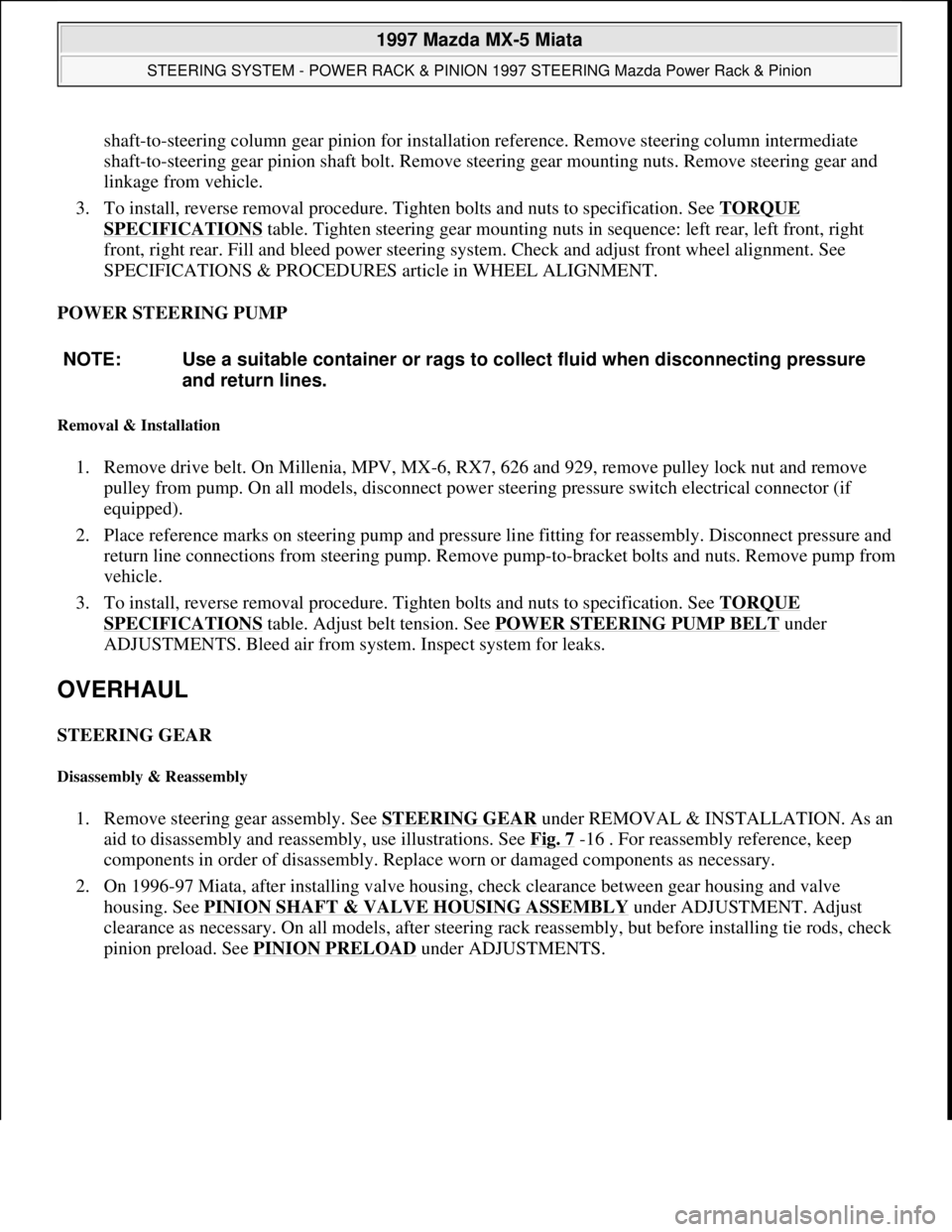
shaft-to-steering column gear pinion for installation reference. Remove steering column intermediate
shaft-to-steering gear pinion shaft bolt. Remove steering gear mounting nuts. Remove steering gear and
linkage from vehicle.
3. To install, reverse removal procedure. Tighten bolts and nuts to specification. See TORQUE
SPECIFICATIONS table. Tighten steering gear mounting nuts in sequence: left rear, left front, right
front, right rear. Fill and bleed power steering system. Check and adjust front wheel alignment. See
SPECIFICATIONS & PROCEDURES article in WHEEL ALIGNMENT.
POWER STEERING PUMP
Removal & Installation
1. Remove drive belt. On Millenia, MPV, MX-6, RX7, 626 and 929, remove pulley lock nut and remove
pulley from pump. On all models, disconnect power steering pressure switch electrical connector (if
equipped).
2. Place reference marks on steering pump and pressure line fitting for reassembly. Disconnect pressure and
return line connections from steering pump. Remove pump-to-
bracket bolts and nuts. Remove pump from
vehicle.
3. To install, reverse removal procedure. Tighten bolts and nuts to specification. See TORQUE
SPECIFICATIONS table. Adjust belt tension. See POWER STEERING PUMP BELT under
ADJUSTMENTS. Bleed air from system. Inspect system for leaks.
OVERHAUL
STEERING GEAR
Disassembly & Reassembly
1. Remove steering gear assembly. See STEERING GEARunder REMOVAL & INSTALLATION. As an
aid to disassembly and reassembly, use illustrations. See Fig. 7
-16 . For reassembly reference, keep
components in order of disassembly. Replace worn or damaged components as necessary.
2. On 1996-97 Miata, after installing valve housing, check clearance between gear housing and valve
housing. See PINION SHAFT & VALVE HOUSING ASSEMBLY
under ADJUSTMENT. Adjust
clearance as necessary. On all models, after steering rack reassembly, but before installing tie rods, check
pinion preload. See PINION PRELOAD
under ADJUSTMENTS. NOTE: Use a suitable container or rags to collect fluid when disconnecting pressure
and return lines.
1997 Mazda MX-5 Miata
STEERING SYSTEM - POWER RACK & PINION 1997 STEERING Mazda Power Rack & Pinion
Microsoft
Sunday, July 05, 2009 1:39:26 PMPage 13 © 2005 Mitchell Repair Information Company, LLC.
Page 368 of 514

1997, 1999-2000 SUSPENSION
Rear - Miata
DESCRIPTION
Rear suspension consists of spring over shock, crossmember, upper and lower arms, and stabilizer bar with
control link. Upper and lower arms attach to crossmember and knuckle. A stabilizer bar with control link is
mounted to lower arm and crossmember. Rear wheel alignment is adjusted by turning adjusting cams on lower
arm. Upper coil over shock mount plate has been redesigned for 1999-2000. New design incorporates a
urethane bumper and improves ride and cornering.
ADJUSTMENTS & INSPECTION
WHEEL ALIGNMENT SPECIFICATIONS & PROCEDURES
WHEEL BEARING ADJUSTMENT
Raise and support vehicle. Remove rear wheel assembly. Remove caliper assembly and ABS wheel speed
sensor. Remove brake rotor. Attach dial indicator to axle hub and measure bearing play. Check bearing axial
play by rocking hub assembly by hand. Maximum bearing play is .002" (.05 mm). If play exceeds specification,
check drive axle lock nut torque or replace wheel bearing. See TORQUE SPECIFICATIONS
.
REMOVAL & INSTALLATION
WHEEL BEARING
Removal
1. Raise and support vehicle. Remove rear wheel assembly. Remove drive axle lock nut. Remove brake
caliper assembly and ABS wheel speed sensor, and wire aside. Remove screws and rotor. Remove ABS
speed sensor bracket. Remove knuckle assembly from upper and lower arms.
2. Using Handle (49-G030-102), Installer (49-G030-727) and Puller (49-F026-103), remove hub from
knuckle. Remove snap ring from knuckle. Using handle, installer and Puller (49-0636-145), remove
wheel bearing inner race from hub. Remove wheel bearing outer race from knuckle using Handle (49-
G030-797), Puller (49-F026-103) and Adapter (49-F027-005).
Inspection
Check wheel hub and knuckle for cracks and damage. Check dust cover for deformation. Check bearing for
excessive wear or seizure. Replace components as necessary.
Installation
NOTE: See SPECIFICATIONS & PROCEDURES article in WHEEL ALIGNMENT.
1997 Mazda MX-5 Miata
1997, 1999-2000 SUSPENSION Rear - Miata
1997 Mazda MX-5 Miata
1997, 1999-2000 SUSPENSION Rear - Miata
Microsoft
Sunday, July 05, 2009 1:38:49 PMPage 1 © 2005 Mitchell Repair Information Company, LLC.
Microsoft
Sunday, July 05, 2009 1:38:53 PMPage 1 © 2005 Mitchell Repair Information Company, LLC.
Page 369 of 514

Press new wheel bearing into knuckle using Handle (49-G030-797), Installer (49-F027-007) and Adapter (49-
F027-009). Press hub into knuckle using adapter. To install, reverse removal procedure. Tighten drive axle lock
nut to specification. See TORQUE SPECIFICATIONS
. Stake drive axle lock nut. Check axial play. See
WHEEL BEARING ADJUSTMENT
.
SHOCK ASSEMBLY
Removal & Disassembly
1. Raise vehicle and remove fuel tank filler pipe protector (1997). Remove rear wheel assembly. Remove
stabilizer bar nut and bolt from lower control arm. Remove 2 upper shock mount-to-body nuts. Remove
lower shock bolt. Lower arms, and remove shock assembly.
2. Clamp shock securely in soft-jaw vise. Compress coil spring. Remove lock nut and washer. Remove
remaining components and note order for reassembly.
Inspection
Check shock for leaks or abnormal noise. Inspect components for wear or damage. Check for loose installation
of bolts and nuts. Replace components as necessary.
Reassembly (1997)
To reassemble, reverse disassembly procedure. To install, reverse removal procedure. Ensure coil spring is
seated in upper and lower seats. See Fig. 1
. Tighten piston rod nut. See TORQUE SPECIFICATIONS. CAUTION: DO NOT lower arms excessively. This may damage brake hose.
1997 Mazda MX-5 Miata
1997, 1999-2000 SUSPENSION Rear - Miata
Microsoft
Sunday, July 05, 2009 1:38:49 PMPage 2 © 2005 Mitchell Repair Information Company, LLC.
Page 372 of 514

Installation
Reinstall shock in reverse order. Tighten nuts and bolts to specification with vehicle resting on ground and
suspension unloaded. See TORQUE SPECIFICATIONS
. Check rear wheel alignment. See
SPECIFICATIONS & PROCEDURES article in WHEEL ALIGNMENT.
LOWER ARM
Removal
Raise and support vehicle. Remove rear wheel assembly. Remove stabilizer bar control link nut and bolt. See
Fig. 3
. Remove lower shock bolt. Remove lower arm-to-crossmember bolts. Remove lower arm-to-knuckle
bolts. Remove lower arm. Inspect arm for damage, cracks and deformation. Check for damaged or worn
bushings.
Installation
To install, reverse removal procedure. Tighten all nuts/bolts to specification with vehicle resting on ground and
suspension unloaded. See TORQUE SPECIFICATIONS
. Adjust rear wheel alignment. See
SPECIFICATIONS & PROCEDURES article in WHEEL ALIGNMENT.
1997 Mazda MX-5 Miata
1997, 1999-2000 SUSPENSION Rear - Miata
Microsoft
Sunday, July 05, 2009 1:38:49 PMPage 5 © 2005 Mitchell Repair Information Company, LLC.