air bleeding MAZDA MIATA 1997 Factory Repair Manual
[x] Cancel search | Manufacturer: MAZDA, Model Year: 1997, Model line: MIATA, Model: MAZDA MIATA 1997Pages: 514, PDF Size: 17.89 MB
Page 23 of 514
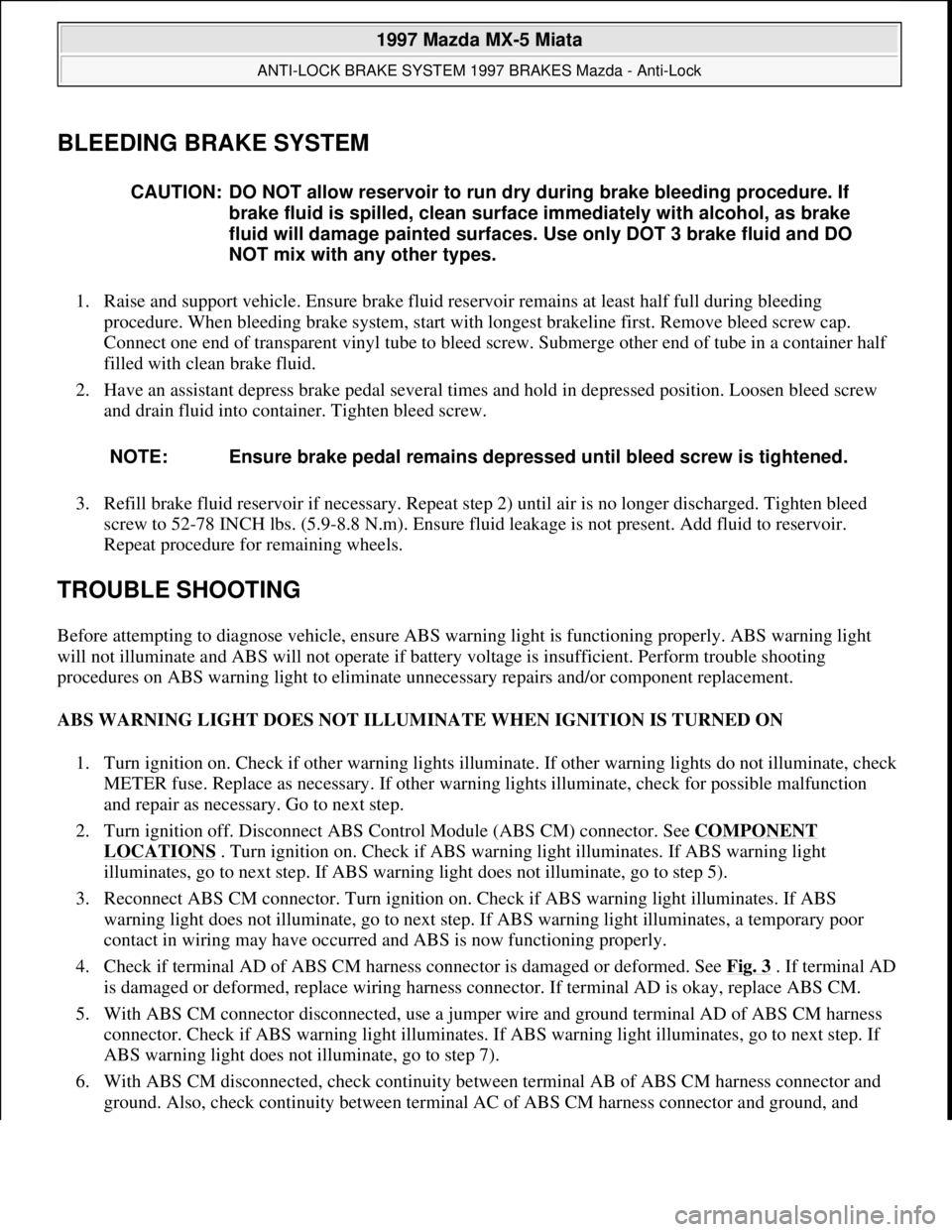
BLEEDING BRAKE SYSTEM
1. Raise and support vehicle. Ensure brake fluid reservoir remains at least half full during bleeding
procedure. When bleeding brake system, start with longest brakeline first. Remove bleed screw cap.
Connect one end of transparent vinyl tube to bleed screw. Submerge other end of tube in a container half
filled with clean brake fluid.
2. Have an assistant depress brake pedal several times and hold in depressed position. Loosen bleed screw
and drain fluid into container. Tighten bleed screw.
3. Refill brake fluid reservoir if necessary. Repeat step 2) until air is no longer discharged. Tighten bleed
screw to 52-78 INCH lbs. (5.9-8.8 N.m). Ensure fluid leakage is not present. Add fluid to reservoir.
Repeat procedure for remaining wheels.
TROUBLE SHOOTING
Before attempting to diagnose vehicle, ensure ABS warning light is functioning properly. ABS warning light
will not illuminate and ABS will not operate if battery voltage is insufficient. Perform trouble shooting
procedures on ABS warning light to eliminate unnecessary repairs and/or component replacement.
ABS WARNING LIGHT DOES NOT ILLUMINATE WHEN IGNITION IS TURNED ON
1. Turn ignition on. Check if other warning lights illuminate. If other warning lights do not illuminate, check
METER fuse. Replace as necessary. If other warning lights illuminate, check for possible malfunction
and repair as necessary. Go to next step.
2. Turn ignition off. Disconnect ABS Control Module (ABS CM) connector. See COMPONENT
LOCATIONS . Turn ignition on. Check if ABS warning light illuminates. If ABS warning light
illuminates, go to next step. If ABS warning light does not illuminate, go to step 5).
3. Reconnect ABS CM connector. Turn ignition on. Check if ABS warning light illuminates. If ABS
warning light does not illuminate, go to next step. If ABS warning light illuminates, a temporary poor
contact in wiring may have occurred and ABS is now functioning properly.
4. Check if terminal AD of ABS CM harness connector is damaged or deformed. See Fig. 3
. If terminal AD
is damaged or deformed, replace wiring harness connector. If terminal AD is okay, replace ABS CM.
5. With ABS CM connector disconnected, use a jumper wire and ground terminal AD of ABS CM harness
connector. Check if ABS warning light illuminates. If ABS warning light illuminates, go to next step. If
ABS warning light does not illuminate, go to step 7).
6. With ABS CM disconnected, check continuity between terminal AB of ABS CM harness connector and
ground. Also, check continuity between terminal AC of ABS CM harness connector and ground, and CAUTION: DO NOT allow reservoir to run dry during brake bleeding procedure. If
brake fluid is spilled, clean surface immediately with alcohol, as brake
fluid will damage painted surfaces. Use only DOT 3 brake fluid and DO
NOT mix with any other types.
NOTE: Ensure brake pedal remains depressed until bleed screw is tightened.
1997 Mazda MX-5 Miata
ANTI-LOCK BRAKE SYSTEM 1997 BRAKES Mazda - Anti-Lock
Microsoft
Sunday, July 05, 2009 1:48:48 PMPage 2 © 2005 Mitchell Repair Information Company, LLC.
Page 42 of 514
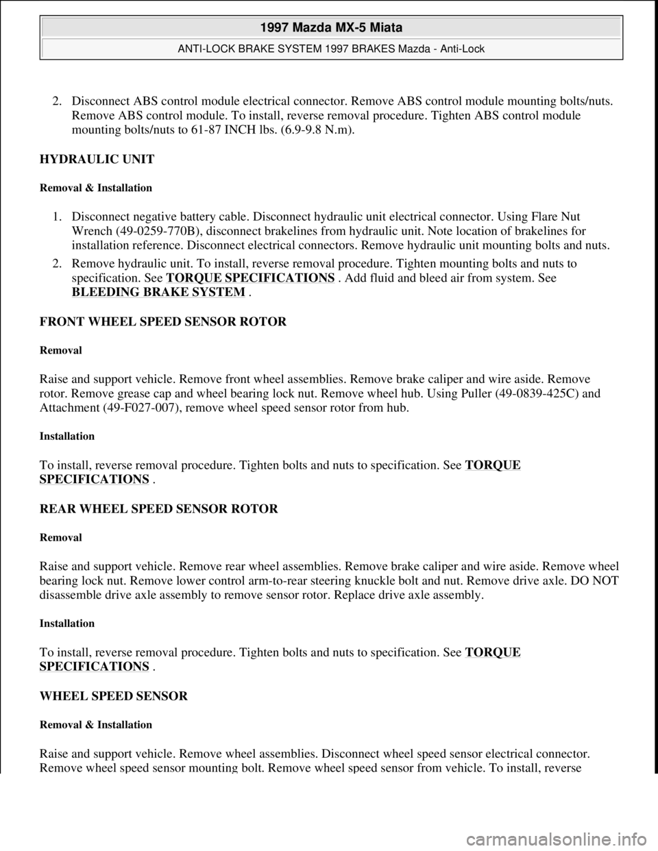
2. Disconnect ABS control module electrical connector. Remove ABS control module mounting bolts/nuts.
Remove ABS control module. To install, reverse removal procedure. Tighten ABS control module
mounting bolts/nuts to 61-87 INCH lbs. (6.9-9.8 N.m).
HYDRAULIC UNIT
Removal & Installation
1. Disconnect negative battery cable. Disconnect hydraulic unit electrical connector. Using Flare Nut
Wrench (49-0259-770B), disconnect brakelines from hydraulic unit. Note location of brakelines for
installation reference. Disconnect electrical connectors. Remove hydraulic unit mounting bolts and nuts.
2. Remove hydraulic unit. To install, reverse removal procedure. Tighten mounting bolts and nuts to
specification. See TORQUE SPECIFICATIONS
. Add fluid and bleed air from system. See
BLEEDING BRAKE SYSTEM
.
FRONT WHEEL SPEED SENSOR ROTOR
Removal
Raise and support vehicle. Remove front wheel assemblies. Remove brake caliper and wire aside. Remove
rotor. Remove grease cap and wheel bearing lock nut. Remove wheel hub. Using Puller (49-0839-425C) and
Attachment (49-F027-007), remove wheel speed sensor rotor from hub.
Installation
To install, reverse removal procedure. Tighten bolts and nuts to specification. See TORQUE
SPECIFICATIONS .
REAR WHEEL SPEED SENSOR ROTOR
Removal
Raise and support vehicle. Remove rear wheel assemblies. Remove brake caliper and wire aside. Remove wheel
bearing lock nut. Remove lower control arm-to-rear steering knuckle bolt and nut. Remove drive axle. DO NOT
disassemble drive axle assembly to remove sensor rotor. Replace drive axle assembly.
Installation
To install, reverse removal procedure. Tighten bolts and nuts to specification. See TORQUE
SPECIFICATIONS .
WHEEL SPEED SENSOR
Removal & Installation
Raise and support vehicle. Remove wheel assemblies. Disconnect wheel speed sensor electrical connector.
Remove wheel speed sensor mounting bolt. Remove wheel speed sensor from vehicle. To install, reverse
1997 Mazda MX-5 Miata
ANTI-LOCK BRAKE SYSTEM 1997 BRAKES Mazda - Anti-Lock
Microsoft
Sunday, July 05, 2009 1:48:49 PMPage 21 © 2005 Mitchell Repair Information Company, LLC.
Page 95 of 514
BRAKE SYSTEM
1995-97 BRAKES Mazda - Disc & Drum
DESCRIPTION & OPERATION
All models use hydraulic-operated brake system with a tandem master cylinder, proportioning valve and a
power brake unit. All models are equipped with front disc brakes and either rear disc or rear drum brakes.
Rear Anti-lock System (RABS) is standard on B2300, B3000, B4000 and MPV models.
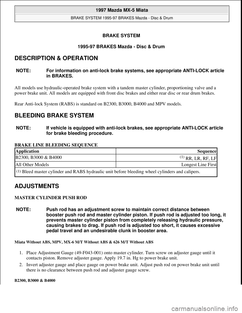
BLEEDING BRAKE SYSTEM
BRAKE LINE BLEEDING SEQUENCE
ADJUSTMENTS
MASTER CYLINDER PUSH ROD
Miata Without ABS, MPV, MX-6 M/T Without ABS & 626 M/T Without ABS
1. Place Adjustment Gauge (49-F043-001) onto master cylinder. Turn screw on adjuster gauge until it
contacts piston. Remove adjuster gauge. Apply 19.7 in. Hg to power brake unit.
2. Invert adjuster gauge and place gauge on power brake unit. Adjust push rod on power brake unit until
there is no clearance between push rod and adjuster gauge screw.
B2300, B3000 & B4000
NOTE: For information on anti-lock brake systems, see appropriate ANTI-LOCK article
in BRAKES.
NOTE: If vehicle is equipped with anti-lock brakes, see appropriate ANTI-LOCK article
for brake bleeding procedure.
ApplicationSequence
B2300, B3000 & B4000(1) RR, LR, RF, LF
All Other ModelsLongest Line First
(1)Bleed master cylinder and RABS hydraulic unit before bleeding wheel cylinders and calipers.
NOTE: Push rod has an adjustment screw to maintain correct distance between
booster push rod and master cylinder piston. If push rod is adjusted too long, it
prevents master cylinder piston from completely releasing hydraulic pressure,
causing brakes to drag. If push rod is adjusted too short, it causes excessive
pedal travel and an undesirable clunk in booster area.
1997 Mazda MX-5 Miata
BRAKE SYSTEM 1995-97 BRAKES Mazda - Disc & Drum
1997 Mazda MX-5 Miata
BRAKE SYSTEM 1995-97 BRAKES Mazda - Disc & Drum
Microsoft
Sunday, July 05, 2009 1:51:02 PMPage 1 © 2005 Mitchell Repair Information Company, LLC.
Microsoft
Sunday, July 05, 2009 1:51:07 PMPage 1 © 2005 Mitchell Repair Information Company, LLC.
Page 103 of 514
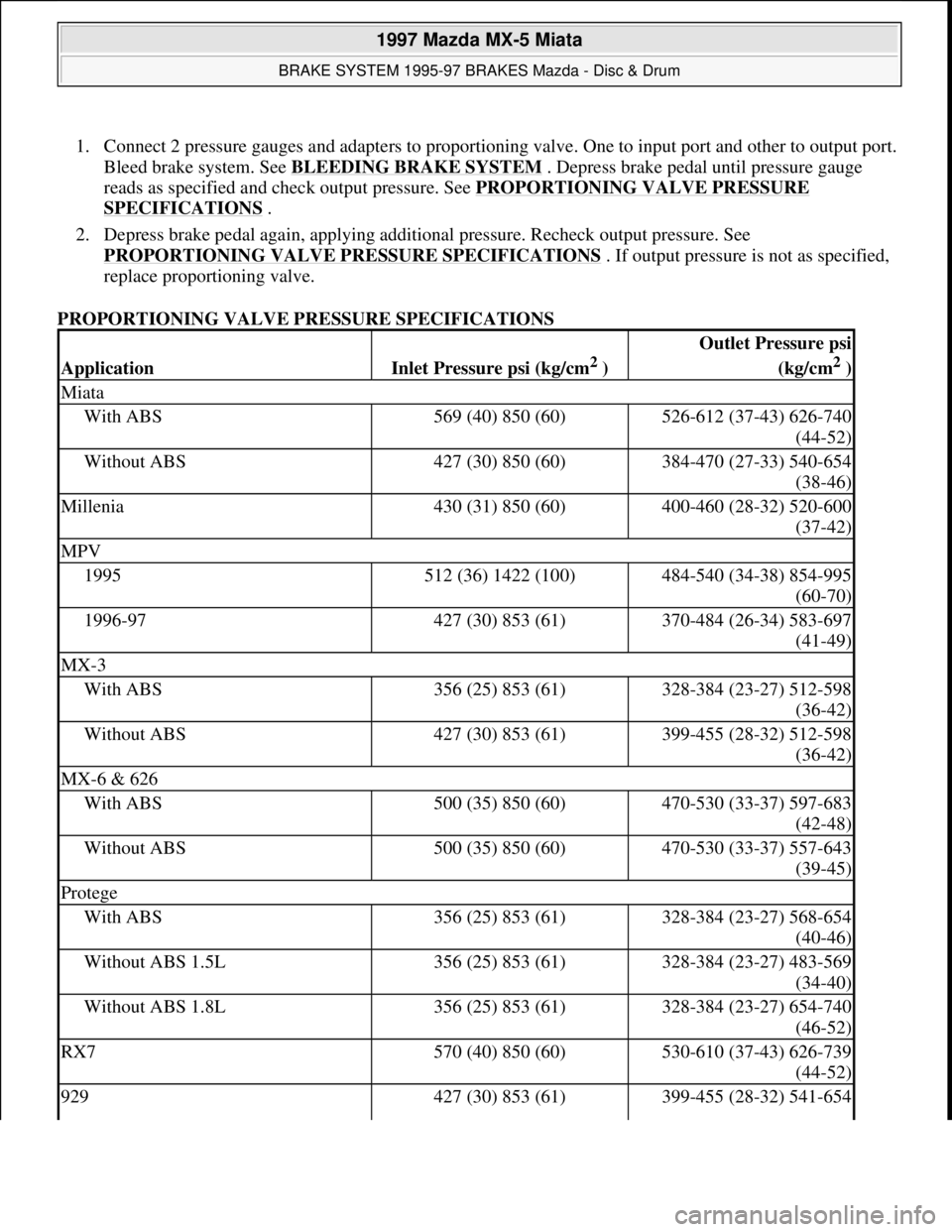
1. Connect 2 pressure gauges and adapters to proportioning valve. One to input port and other to output port.
Bleed brake system. See BLEEDING BRAKE SYSTEM
. Depress brake pedal until pressure gauge
reads as specified and check output pressure. See PROPORTIONING VALVE PRESSURE
SPECIFICATIONS .
2. Depress brake pedal again, applying additional pressure. Recheck output pressure. See
PROPORTIONING VALVE PRESSURE SPECIFICATIONS
. If output pressure is not as specified,
replace proportioning valve.
PROPORTIONING VALVE PRESSURE SPECIFICATIONS
ApplicationInlet Pressure psi (kg/cm2 )
Outlet Pressure psi
(kg/cm
2 )
Miata
With ABS569 (40) 850 (60)526-612 (37-43) 626-740
(44-52)
Without ABS427 (30) 850 (60)384-470 (27-33) 540-654
(38-46)
Millenia430 (31) 850 (60)400-460 (28-32) 520-600
(37-42)
MPV
1995512 (36) 1422 (100)484-540 (34-38) 854-995
(60-70)
1996-97427 (30) 853 (61)370-484 (26-34) 583-697
(41-49)
MX-3
With ABS356 (25) 853 (61)328-384 (23-27) 512-598
(36-42)
Without ABS427 (30) 853 (61)399-455 (28-32) 512-598
(36-42)
MX-6 & 626
With ABS500 (35) 850 (60)470-530 (33-37) 597-683
(42-48)
Without ABS500 (35) 850 (60)470-530 (33-37) 557-643
(39-45)
Protege
With ABS356 (25) 853 (61)328-384 (23-27) 568-654
(40-46)
Without ABS 1.5L356 (25) 853 (61)328-384 (23-27) 483-569
(34-40)
Without ABS 1.8L356 (25) 853 (61)328-384 (23-27) 654-740
(46-52)
RX7570 (40) 850 (60)530-610 (37-43) 626-739
(44-52)
929427 (30) 853 (61)399-455 (28-32) 541-654
1997 Mazda MX-5 Miata
BRAKE SYSTEM 1995-97 BRAKES Mazda - Disc & Drum
Microsoft
Sunday, July 05, 2009 1:51:03 PMPage 9 © 2005 Mitchell Repair Information Company, LLC.
Page 158 of 514

CLUTCH DISENGAGEMENT HEIGHT (MINIMUM) (1)
Fig. 1: Adjusting Clutch Pedal (Miata)
Courtesy of MAZDA MOTORS CORP.
HYDRAULIC SYSTEM BLEEDING
B2300, B2500, B3000 & B4000
ApplicationIn. (mm)
Miata2.68 (68)
(1)Measure to carpet on bulkhead. See Fig. 1 .
1997 Mazda MX-5 Miata
CLUTCH 1997-98 CLUTCHES Mazda - RWD
Microsoft
Sunday, July 05, 2009 1:36:47 PMPage 2 © 2005 Mitchell Repair Information Company, LLC.
Page 159 of 514
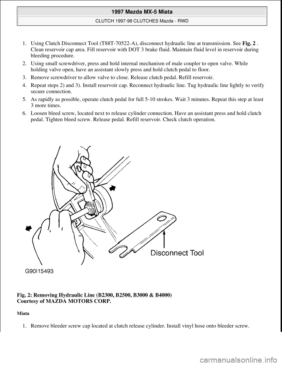
1. Using Clutch Disconnect Tool (T88T-70522-A), disconnect hydraulic line at transmission. See Fig. 2 .
Clean reservoir cap area. Fill reservoir with DOT 3 brake fluid. Maintain fluid level in reservoir during
bleeding procedure.
2. Using small screwdriver, press and hold internal mechanism of male coupler to open valve. While
holding valve open, have an assistant slowly press and hold clutch pedal to floor.
3. Remove screwdriver to allow valve to close. Release clutch pedal. Refill reservoir.
4. Repeat steps 2) and 3). Install reservoir cap. Reconnect hydraulic line. Tug hydraulic line lightly to verify
secure connection.
5. As rapidly as possible, operate clutch pedal for full 5-10 strokes. Wait 3 minutes. Repeat this step at least
3 more times.
6. Loosen bleed screw, located next to release cylinder connection. Have an assistant press and hold clutch
pedal. Tighten bleed screw. Release pedal. Refill reservoir. Check clutch operation.
Fig. 2: Removing Hydraulic Line (B2300, B2500, B3000 & B4000)
Courtesy of MAZDA MOTORS CORP.
Miata
1. Remove bleeder screw cap located at clutch release cylinder. Install vinyl hose onto bleeder screw.
1997 Mazda MX-5 Miata
CLUTCH 1997-98 CLUTCHES Mazda - RWD
Microsoft
Sunday, July 05, 2009 1:36:47 PMPage 3 © 2005 Mitchell Repair Information Company, LLC.
Page 161 of 514
Installation (B2300, B2500, B3000 & B4000)
1. Lightly coat input shaft splines, release bearing, and fork contact areas with molybdenum disulfide
grease. Align clutch cover dowel holes with flywheel dowels. Tighten clutch cover bolts evenly in a
crisscross pattern to specification. See TORQUE SPECIFICATIONS
.
2. Raise transmission into position. Install and tighten transmission-to-engine block bolts. See TORQUE
SPECIFICATIONS . Install crossmember.
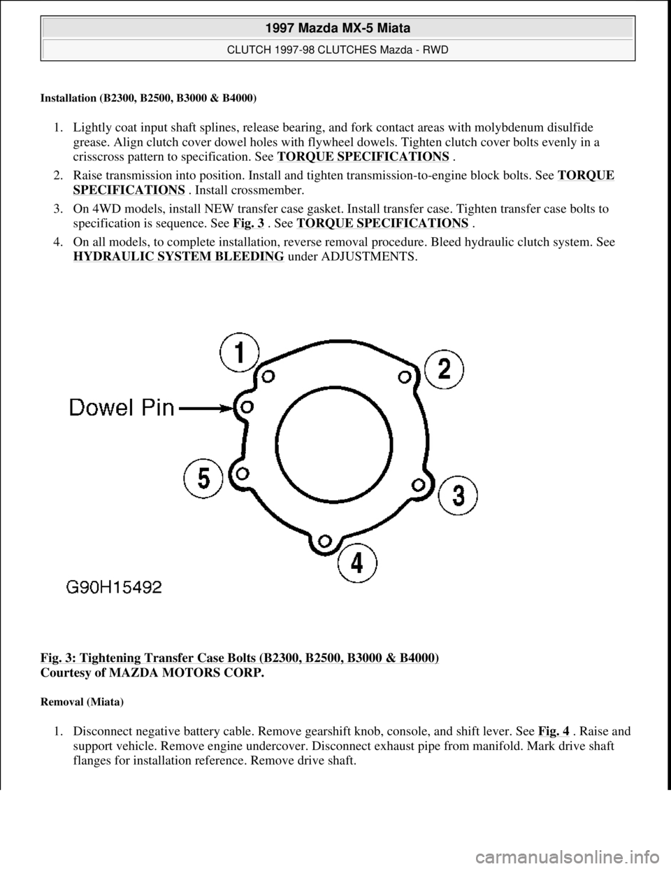
3. On 4WD models, install NEW transfer case gasket. Install transfer case. Tighten transfer case bolts to
specification is sequence. See Fig. 3
. See TORQUE SPECIFICATIONS .
4. On all models, to complete installation, reverse removal procedure. Bleed hydraulic clutch system. See
HYDRAULIC SYSTEM BLEEDING
under ADJUSTMENTS.
Fig. 3: Tightening Transfer Case Bolts (B2300, B2500, B3000 & B4000)
Courtesy of MAZDA MOTORS CORP.
Removal (Miata)
1. Disconnect negative battery cable. Remove gearshift knob, console, and shift lever. See Fig. 4. Raise and
support vehicle. Remove engine undercover. Disconnect exhaust pipe from manifold. Mark drive shaft
flanges for installation reference. Remove drive shaft.
1997 Mazda MX-5 Miata
CLUTCH 1997-98 CLUTCHES Mazda - RWD
Microsoft
Sunday, July 05, 2009 1:36:47 PMPage 5 © 2005 Mitchell Repair Information Company, LLC.
Page 169 of 514
Installation
Insert master cylinder push rod through opening in bulkhead. Install master cylinder. Connect hydraulic lines.
Install fluid reservoir. Install push rod on clutch pedal. Bleed hydraulic system. See HYDRAULIC SYSTEM
BLEEDING .
Removal & Installation (Miata)
Disconnect hydraulic line and master cylinder mounting nuts. Disengage push rod from clutch pedal. Remove
master cylinder. To install, reverse removal procedure and bleed hydraulic system. See HYDRAULIC
SYSTEM BLEEDING .
CLUTCH RELEASE CYLINDER
Removal & Installation (B2300, B2500, B3000 & B4000)
Release cylinder is removed with clutch. See CLUTCH ASSEMBLY.
Removal & Installation (Miata)
Raise and support vehicle. Disconnect and plug hydraulic line. Remove clutch release cylinder. To install,
reverse removal procedure. Bleed hydraulic system. See HYDRAULIC SYSTEM BLEEDING
.
OVERHAUL
CLUTCH MASTER CYLINDER disconnected.
NOTE: Overhaul procedures for B2300, B2500, B3000 and B4000 are not available.
NOTE: Use exploded view of clutch master cylinder for overhaul procedure. See Fig.
10 .
1997 Mazda MX-5 Miata
CLUTCH 1997-98 CLUTCHES Mazda - RWD
Microsoft
Sunday, July 05, 2009 1:36:47 PMPage 13 © 2005 Mitchell Repair Information Company, LLC.
Page 208 of 514
Remove rear seat cushions. Disconnect fuel pump connector. Start engine and allow to stall. After engine stalls,
attempt to restart engine to ensure no residual pressure exists. Turn ignition off and reconnect fuel pump
connector. When disconnecting fuel hoses, cover connection with shop rag to catch fuel leakage. To avoid
excessive cranking after servicing, prime fuel system before starting engine.
Priming System
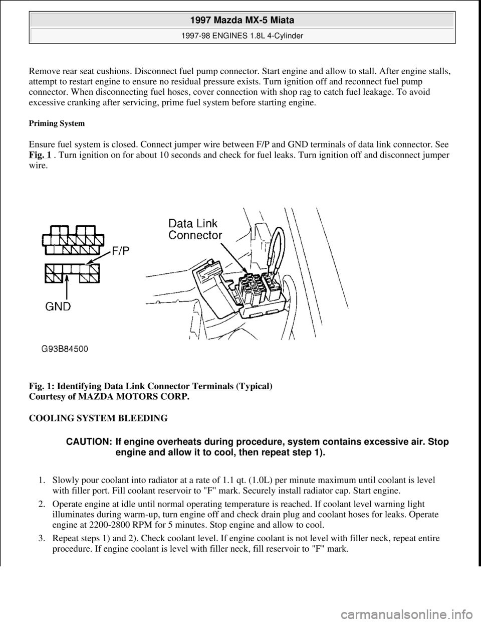
Ensure fuel system is closed. Connect jumper wire between F/P and GND terminals of data link connector. See
Fig. 1
. Turn ignition on for about 10 seconds and check for fuel leaks. Turn ignition off and disconnect jumper
wire.
Fig. 1: Identifying Data Link Connector Terminals (Typical)
Courtesy of MAZDA MOTORS CORP.
COOLING SYSTEM BLEEDING
1. Slowly pour coolant into radiator at a rate of 1.1 qt. (1.0L) per minute maximum until coolant is level
with filler port. Fill coolant reservoir to "F" mark. Securely install radiator cap. Start engine.
2. Operate engine at idle until normal operating temperature is reached. If coolant level warning light
illuminates during warm-up, turn engine off and check drain plug and coolant hoses for leaks. Operate
engine at 2200-2800 RPM for 5 minutes. Stop engine and allow to cool.
3. Repeat steps 1) and 2). Check coolant level. If engine coolant is not level with filler neck, repeat entire
procedure. If engine coolant is level with filler neck, fill reservoir to "F" mark.
CAUTION: If engine overheats during procedure, system contains excessive air. Stop
engine and allow it to cool, then repeat step 1).
1997 Mazda MX-5 Miata
1997-98 ENGINES 1.8L 4-Cylinder
Microsoft
Sunday, July 05, 2009 1:55:15 PMPage 2 © 2005 Mitchell Repair Information Company, LLC.
Page 212 of 514
differential housing block.
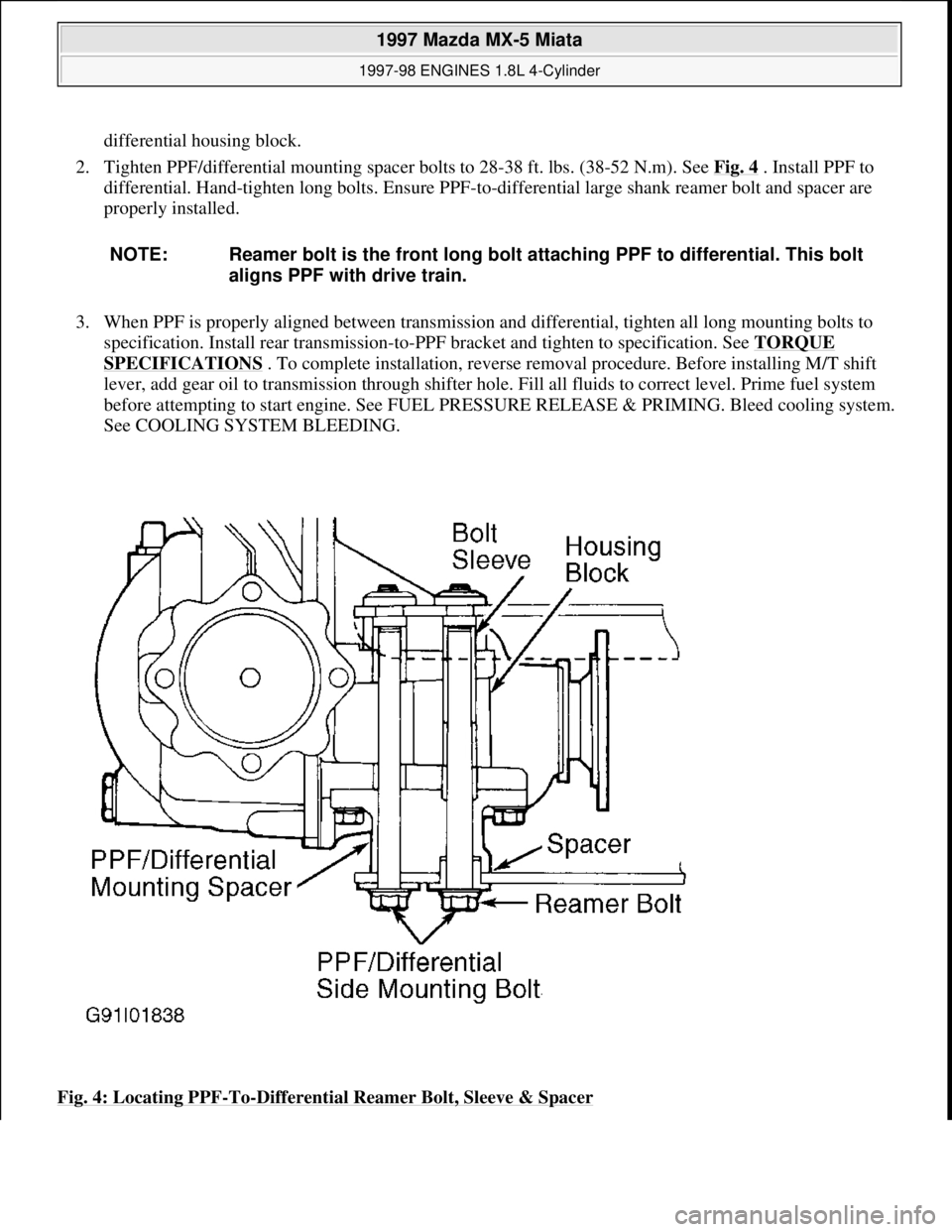
2. Tighten PPF/differential mounting spacer bolts to 28-38 ft. lbs. (38-52 N.m). See Fig. 4
. Install PPF to
differential. Hand-tighten long bolts. Ensure PPF-to-differential large shank reamer bolt and spacer are
properly installed.
3. When PPF is properly aligned between transmission and differential, tighten all long mounting bolts to
specification. Install rear transmission-to-PPF bracket and tighten to specification. See TORQUE
SPECIFICATIONS . To complete installation, reverse removal procedure. Before installing M/T shift
lever, add gear oil to transmission through shifter hole. Fill all fluids to correct level. Prime fuel system
before attempting to start engine. See FUEL PRESSURE RELEASE & PRIMING. Bleed cooling system.
See COOLING SYSTEM BLEEDING.
Fig. 4: Locating PPF
-To-Differential Reamer Bolt, Sleeve & Spacer
NOTE: Reamer bolt is the front long bolt attaching PPF to differential. This bolt
aligns PPF with drive train.
1997 Mazda MX-5 Miata
1997-98 ENGINES 1.8L 4-Cylinder
Microsoft
Sunday, July 05, 2009 1:55:15 PMPage 6 © 2005 Mitchell Repair Information Company, LLC.