maintenance MAZDA MODEL B-SERIES 2002 Owners Manual (in English)
[x] Cancel search | Manufacturer: MAZDA, Model Year: 2002, Model line: MODEL B-SERIES, Model: MAZDA MODEL B-SERIES 2002Pages: 287, PDF Size: 2.47 MB
Page 3 of 287

Maintenance and Specifications 224
Hood 233
Engine compartment 234
Engine oil 238
Battery 244
Fuel information 251
Refill capacities 273
Lubricant specifications 276
Engine data 277
Vehicle dimensions 277
Accessories 280
Index 281
All rights reserved. Reproduction by any means, electronic or mechanical
including photocopying, recording or by any information storage and retrieval
system or translation in whole or part is not permitted without written
authorization from Mazda Motor Corporation. Mazda may change the contents
without notice and without incurring obligation.
Copyright 2001 Mazda Motor Corporation
Table of Contents
3
Page 17 of 287

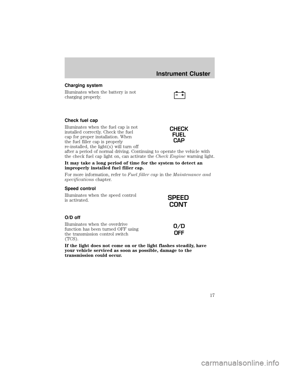
Charging system
Illuminates when the battery is not
charging properly.
Check fuel cap
Illuminates when the fuel cap is not
installed correctly. Check the fuel
cap for proper installation. When
the fuel filler cap is properly
re-installed, the light(s) will turn off
after a period of normal driving. Continuing to operate the vehicle with
the check fuel cap light on, can activate theCheck Enginewarning light.
It may take a long period of time for the system to detect an
improperly installed fuel filler cap.
For more information, refer toFuel filler capin theMaintenance and
specificationschapter.
Speed control
Illuminates when the speed control
is activated.
O/D off
Illuminates when the overdrive
function has been turned OFF using
the transmission control switch
(TCS).
If the light does not come on or the light flashes steadily, have
your vehicle serviced as soon as possible, damage to the
transmission could occur.
CHECK
FUEL
CAP
SPEED
CONT
O/D
OFF
Instrument Cluster
17
Page 20 of 287

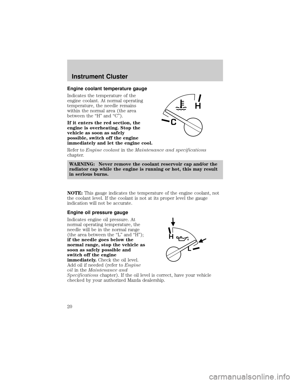
Engine coolant temperature gauge
Indicates the temperature of the
engine coolant. At normal operating
temperature, the needle remains
within the normal area (the area
between the ªHº and ªCº).
If it enters the red section, the
engine is overheating. Stop the
vehicle as soon as safely
possible, switch off the engine
immediately and let the engine cool.
Refer toEngine coolantin theMaintenance and specifications
chapter.
WARNING: Never remove the coolant reservoir cap and/or the
radiator cap while the engine is running or hot, this may result
in serious burns.
NOTE:This gauge indicates the temperature of the engine coolant, not
the coolant level. If the coolant is not at its proper level the gauge
indication will not be accurate.
Engine oil pressure gauge
Indicates engine oil pressure. At
normal operating temperature, the
needle will be in the normal range
(the area between the ªLº and ªHº);
if the needle goes below the
normal range, stop the vehicle as
soon as safely possible and
switch off the engine
immediately.Check the oil level.
Add oil if needed (refer toEngine
oilin theMaintenance and
Specificationschapter). If the oil level is correct, have your vehicle
checked by your authorized Mazda dealership.
C
H
H
L
Instrument Cluster
20
Page 117 of 287

WARNING: After any vehicle collision, the seat belt system at
all outboard seating positions (except driver, which has no
ªautomatic locking retractorº feature) must be checked by a
qualified technician to verify that the ªautomatic locking
retractorº feature for child seats is still functioning properly. In
addition, all seat belts should be checked for proper function.
WARNING: BELT AND RETRACTOR ASSEMBLY MUST BE
REPLACED if the seat belt assembly ªautomatic locking
retractorº feature or any other seat belt function is not
operating properly when checked according to the procedures in
Workshop Manual.
WARNING: Failure to replace the Belt and Retractor assembly
could increase the risk of injury in collisions.
Safety belt pretensioner
Your vehicle is equipped with safety belt pretensioners at the driver and
front outboard passenger seating positions.
The safety belt pretensioners are designed to activate during certain
frontal or near-frontal collisions with sufficient longitudinal deceleration.
A safety belt pretensioner is a device which tightens the webbing of the
lap and shoulder belts in such a way that they fit more snugly against
the body.
The driver and front outboard passenger safety belt system (including
retractors, buckle assembly, pretensioner assembly with seat and height
adjusters) must be replaced if the vehicle is involved in a collision that
results in the activation of the safety belt pretensioners. Refer to the
Safety belt maintenancesection in this chapter.
WARNING: Failure to replace the safety belt assembly under
the above conditions could result in severe personal injuries in
the event of a collision.
Seating and Safety Restraints
117
Page 124 of 287

4. Turn on the parklamps/headlamps, turn off the
parklamps/headlamps.
5. Buckle then unbuckle the safety belt three times, ending with the
safety belt unbuckled.
²After step 5 the safety belt warning light will be turned on for three
seconds.
6. Within seven seconds of the safety belt warning light turning off,
buckle then unbuckle the safety belt.
²This will disable BeltMinder if it is currently enabled, or enable
BeltMinder if it is currently disabled.
7. Confirmation of disabling BeltMinder is provided by the safety belt
warning light flashing four times per second for three seconds.
8. Confirmation of enabling BeltMinder is provided by:
²The safety belt warning light flashing four times per second for three
seconds.
²Followed by three seconds with the safety belt warning light off.
²Once again, the safety belt warning light will flash four times per
second for three seconds.
9. After receiving confirmation, the deactivation/activation procedure is
complete.
Safety belt maintenance
Inspect the safety belt systems periodically to make sure they work
properly and are not damaged.
NOTE:
If unsure about the proper procedures, bring your vehicle to an
authorized Mazda dealership for inspection. Inspect the safety belts to
make sure there are no nicks, tears or cuts, replacing if necessary. All
safety belt assemblies, including retractors, buckles, front seat belt buckle
assemblies, buckle support assemblies (slide bar-if equipped), shoulder
belt height adjusters (if equipped), shoulder belt guide on seatback (if
equipped), child safety seat tether bracket assemblies (if equipped),
LATCH child seat tether anchors and lower anchors (if equipped), and
attaching hardware, should be inspected after a collision. Mazda
recommends that all safety belt assemblies used in vehicles involved in a
collision be replaced. However, if the collision was minor and an
authorized Mazda technician finds that the belts do not show damage and
continue to operate properly, they do not need to be replaced. Safety belt
Seating and Safety Restraints
124
Page 129 of 287

WARNING: Several air bag system components get hot after
inflation. Do not touch them after inflation or you may be
burned.
WARNING: If the air bag has deployed, the air bag will not
function again and must be replaced immediately. If the air bag
is not replaced, the unrepaired area will increase the risk of
injury in a collision.
The SRS consists of:
²driver and passenger air bag modules (which include the inflators and
air bags),
²passenger air bag deactivation switch and restraint control module
(RCM)
²a readiness light and tone,
²and the electrical wiring which connects the components.
The RCM (restraints control module) monitors its own internal circuits
and the supplemental air bag electrical system warning (including the
passenger air bag deactivation switch, the system wiring, the air bag
system readiness light, the air bag back up power and the air bag
ignitors).
Determining if the system is operational
The SRS uses readiness lights in the instrument cluster and the
passenger air bag deactivate switch or a tone to indicate the condition of
the system. Refer to theAir bag readinesssection in the
Instrumentationchapter orPassenger air bag deactivate switch
section in this chapter. Routine maintenance of the air bag is not
required.
A difficulty with the system is indicated by one or more of the following:
²The readiness lights will either
flash or stay lit.
²The readiness lights will not
illuminate immediately after
ignition is turned on.
Seating and Safety Restraints
129
Page 152 of 287

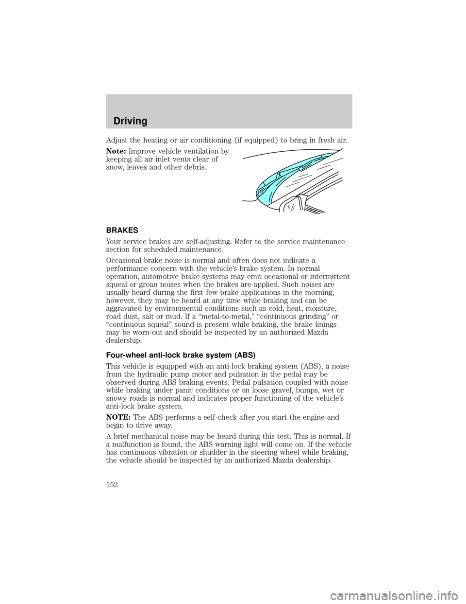
Adjust the heating or air conditioning (if equipped) to bring in fresh air.
Note:Improve vehicle ventilation by
keeping all air inlet vents clear of
snow, leaves and other debris.
BRAKES
Your service brakes are self-adjusting. Refer to the service maintenance
section for scheduled maintenance.
Occasional brake noise is normal and often does not indicate a
performance concern with the vehicle's brake system. In normal
operation, automotive brake systems may emit occasional or intermittent
squeal or groan noises when the brakes are applied. Such noises are
usually heard during the first few brake applications in the morning;
however, they may be heard at any time while braking and can be
aggravated by environmental conditions such as cold, heat, moisture,
road dust, salt or mud. If a ªmetal-to-metal,º ªcontinuous grindingº or
ªcontinuous squealº sound is present while braking, the brake linings
may be worn-out and should be inspected by an authorized Mazda
dealership.
Four-wheel anti-lock brake system (ABS)
This vehicle is equipped with an anti-lock braking system (ABS), a noise
from the hydraulic pump motor and pulsation in the pedal may be
observed during ABS braking events. Pedal pulsation coupled with noise
while braking under panic conditions or on loose gravel, bumps, wet or
snowy roads is normal and indicates proper functioning of the vehicle's
anti-lock brake system.
NOTE:The ABS performs a self-check after you start the engine and
begin to drive away.
A brief mechanical noise may be heard during this test. This is normal. If
a malfunction is found, the ABS warning light will come on. If the vehicle
has continuous vibration or shudder in the steering wheel while braking,
the vehicle should be inspected by an authorized Mazda dealership.
Driving
152
Page 177 of 287

Refer to the following chart for information regarding the
factory-equipped trailer tow connector:
Trailer tow connector
Color Function Comment
1. Dark Green Trailer right-hand
turn signalCircuit activated when brake
pedal is depressed or when
ignition is on and right-hand
turn signal is applied.
2. Yellow Trailer left-hand turn
signalCircuit activated when brake
pedal is depressed or when
ignition is on and left-hand
turn signal is applied.
3. Tan/White Tail lamp Relay controlled circuit
activated when the park
lamps/headlamps are on.
4. White Ground Matching vehicle circuit
returns to battery's negative
ground.
Driving while you tow
When towing a trailer:
²Ensure that you turn off your speed control. The speed control may
shut off automatically when you are towing on long, steep grades.
²Consult your local motor vehicle speed regulations for towing a trailer.
²Use a lower gear when towing up or down steep hills. This will
eliminate excessive downshifting and upshifting for optimum fuel
economy and transmission cooling.
²Anticipate stops and brake gradually.
Exceeding the GCWR rating may cause internal transmission
damage and void your warranty coverage.
Servicing after towing
If you tow a trailer for long distances, your vehicle will require more
frequent service intervals. Refer to your service maintenance section for
more information.
Driving
177
Page 188 of 287

WARNING: To reduce risk of electrical shock, always replace
the cover to the Power Distribution Box before reconnecting
the battery or refilling fluid reservoirs.
If the battery has been disconnected and reconnected, refer to the
Batterysection of theMaintenance and specificationschapter.
2.3L engine (if equipped)
The high-current fuses are coded as follows:
Fuse/Relay
LocationFuse Amp
RatingPower Distribution Box
Description
1 50A** I/P Fuse Panel
2 Ð Not Used
3 Ð Not Used
4 Ð Not Used
5 Ð Not Used
6 50A** ABS Pump Motor
7 30A* Powertrain Control Module (PCM)
1234521 22 23 24
25 26 27 28
29 30 31 32
33 34 35 36
37 38 39 40
41 42 43 44
67891055
49 4854 53 52
515656 B
56 A
5050 B
50 A 47 4545 B
45 A
4646 B
46 A 11 12 13 14 15
16 17 18 19 20
Roadside Emergencies
188
Page 215 of 287

(Note)
If you live in the U.S.A., all correspondence to Mazda Motor Corporation
should be forwarded to:
Mazda North American Operations
7755, Irvine Center Drive
Irvine, California 92618±2922
P.O. Box 19734
Irvine, CA 92623±9734
Customer Assistance Center
or toll free at 1 (800) 222±5500
If you live outside of the U.S.A., please contact the nearest Mazda
Distributor. ( See theMazda Importers/Distributorssection of this
manual).
SERVICE PUBLICATIONS
Factory-authorized Mazda service publication are available for owners
who wish to do some of their own maintenance and repair.
When requesting any of our publications through an Authorized Mazda
Dealer, refer to the chart below.
If they don't have what you need in stock, they can order it for you.
PUBLICATION ORDER NUMBER PUBLICATION DESCRIPTION
9999 95 022B 02 2002 WORKSHOP MANUAL
9999 95 020G 02 2002 WIRING DIAGRAM
9999 95 023C 02 2002 OWNER'S MANUAL
WORKSHOP MANUAL:
Covers recommended maintenance and repair procedures of the drive
train, body and chassis.
WIRING DIAGRAM:
Provides electrical schematics as well as component location for the
entire electrical system.
OWNER'S MANUAL:
This booklet contains information regarding the proper care and
operation of your vehicle. This is not a technician's manual.
Please note that your Authorized Mazda Dealership has trained
personnel and special service tools to correctly and safely
maintain Mazda vehicles.
Customer Assistance
215