lock MAZDA MODEL B2300 2003 (in English) User Guide
[x] Cancel search | Manufacturer: MAZDA, Model Year: 2003, Model line: MODEL B2300, Model: MAZDA MODEL B2300 2003Pages: 248, PDF Size: 2.71 MB
Page 42 of 248

WARNING: Handling Halogen Bulbs: When a halogen bulb
breaks, it is dangerous. These bulbs contain pressurized gas. If
one is broken, it will explode and serious injuries could be
caused by the flying glass. If the glass portion of the bulb is
touched with bare hands, body oil could cause the bulb to
overheat and explode when lit. Never touch the glass portion of
the bulb with your bare hands and always wear eye protection
when handling or working around halogen bulbs.
Children and Halogen Bulbs: Playing with a halogen bulb is
dangerous. Serious injuries could be caused by dropping a
halogen bulb or breaking in some other way. Always keep
halogen bulbs out of the reach of children.
To remove the headlamp bulb:
1. Make sure headlamp switch is in
OFF position, then open the
hood.
2. At the back of the headlamp,
pry up the two retainer pins to
release the headlamp assembly
from the vehicle and pull
headlamp forward.
3. Remove the bulb retaining ring
by rotating it counterclockwise
(when viewed from the rear) to
free it from the bulb socket, and
slide the ring off the plastic
base. Keep the ring to retain the
new bulb.
4. Without turning, remove the old
bulb by gently pulling it straight
back out of the lamp assembly.
Lights
42
Page 43 of 248

To install the new bulb:
Handle a halogen headlamp bulb carefully and keep out of
children's reach. Grasp the bulb only by its plastic base and do
not touch the glass. The oil from your hands could cause the bulb
to break the next time the headlamps are operated. Always wear
safety glasses while handling bulbs.
NOTE: If the bulb is accidentally touched, it should be cleaned with
rubbing alcohol before being used.
1. With the flat side of the bulb's plastic base facing upward, insert the
glass end of the bulb into the lamp assembly. You may need to turn
the bulb left or right to align the grooves in the plastic base with the
tabs in the lamp assembly. When the grooves are aligned, push the
bulb into the lamp assembly until the plastic base contacts the rear
of the lamp assembly.
2. Install the bulb retaining ring over the plastic base until it contacts
the rear of the socket by rotating clockwise until you feel a ªstop.º
3. Install the electrical connector into the plastic base until it snaps,
locking it into position.
4. Install the headlamp on vehicle, push rearward and secure with two
retainer pins.
5. Turn the headlamps on and make sure they work properly. If the
headlamp was correctly aligned before you changed the bulb, you
should not need to align it again.
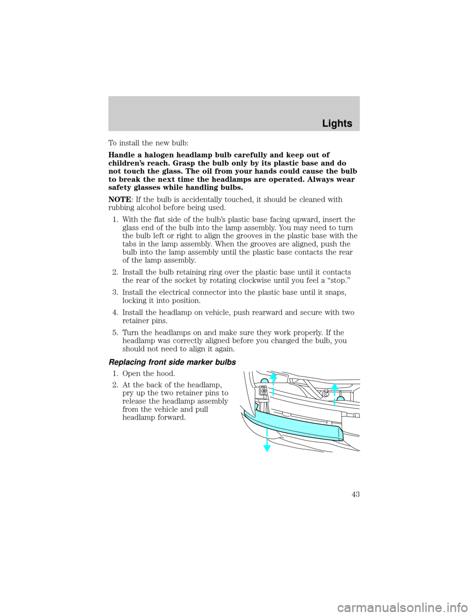
Replacing front side marker bulbs
1. Open the hood.
2. At the back of the headlamp,
pry up the two retainer pins to
release the headlamp assembly
from the vehicle and pull
headlamp forward.
Lights
43
Page 44 of 248

3. Remove screw(s) from lamp
assembly.
4. Disengage lamp assembly (it has
a snap fit).
5. Rotate bulb socket
counterclockwise and remove
from lamp assembly.
6. Carefully pull bulb straight out
of socket and push in the new
bulb.
7. Install the bulb socket in lamp
assembly by turning clockwise.
8. Align the lamp on the vehicle
and push to snap in place.
9. Install screw(s) on lamp assembly.
10. Install the headlamp on vehicle, push rearward and secure with two
retainer pins.
Lights
44
Page 45 of 248

Replacing tail lamp/backup lamp bulbs
The tail lamp/backup lamp bulbs are
located in the same portion of the
tail lamp assembly, one just below
the other. Follow the same steps to
replace either bulb:
1. Open the tailgate to expose the
lamp assemblies.
2. Remove the four screws and the
lamp assembly from vehicle.
3. Rotate bulb socket
counterclockwise turn and
remove from lamp assembly.
4. Carefully pull the bulb straight
out of the socket and push in
the new bulb.
5. Install the bulb socket in lamp
assembly by turning clockwise.
6. Install the lamp assembly and
secure with four screws.
Replacing fog lamp bulbs
1. Remove the bulb socket from
the fog lamp by turning
counterclockwise.
2. Disconnect the electrical
connector from the fog lamp
bulb.
3. Connect the electrical connector to the new fog lamp bulb.
4. Install the bulb socket in the fog lamp turning clockwise.
Lights
45
Page 46 of 248

Replacing high-mount brake lamp and cargo lamp bulbs
The replacement of the high-mount brake lamp bulb and cargo lamp bulb
is basically the same. This procedure covers the high-mount brake lamp
bulb.
To remove the brake lamp assembly:
1. Remove the two screws and
lamp assembly from vehicle.
2. Remove the bulb socket from
lamp assembly by rotating it
counterclockwise.
3. Carefully pull bulb straight out
of socket and push in the new
bulb.
To install the brake lamp assembly:
1. Install the bulb socket into the
lamp assembly by rotating
clockwise.
2. Install the lamp assembly on the vehicle and secure with two screws.
Replacing license plate lamp bulbs
The license plate bulbs are located
behind the rear bumper. To change
the license plate lamp bulbs:
1. Reach behind the rear bumper
to locate the bulb socket.
2. Twist the socket
counterclockwise and remove.
3. Pull out the old bulb from
socket and push in the new
bulb.
4. Install the bulb socket in lamp assembly by turning it clockwise.
Lights
46
Page 48 of 248

Changing the wiper blades
1. Pull the wiper arm away from
the vehicle. Turn the blade at an
angle from the wiper arm. Push
the lock pin manually to release
the blade and pull the wiper
blade down toward the
windshield to remove it from
the arm.
2. Attach the new wiper to the
wiper arm and press it into
place until a click is heard.
3. Replace wiper blades every 6 months for optimum performance.
TILT STEERING WHEEL (IF EQUIPPED)
To adjust the steering wheel:
1. Pull and hold the steering wheel
release control toward you.
2. Move the steering wheel up or
down until you find the desired
location.
3. Release the steering wheel
release control. This will lock
the steering wheel in position.
WARNING: Never adjust the steering wheel when the vehicle is
moving.
Driver Controls
48
Page 50 of 248

AUTOMATIC DIMMING REAR VIEW MIRRORS (IF EQUIPPED)
The electronic day/night mirror will change from the normal state to the
non-glare state when bright lights (glare) reach the inside rear view
mirror. When the inside rear view mirror detects bright light from behind
the vehicle, the inside rear view mirror will automatically adjust (darken)
to minimize glare.
Do not block the sensor on the backside of the inside rear view mirror
since this may impair proper system performance.
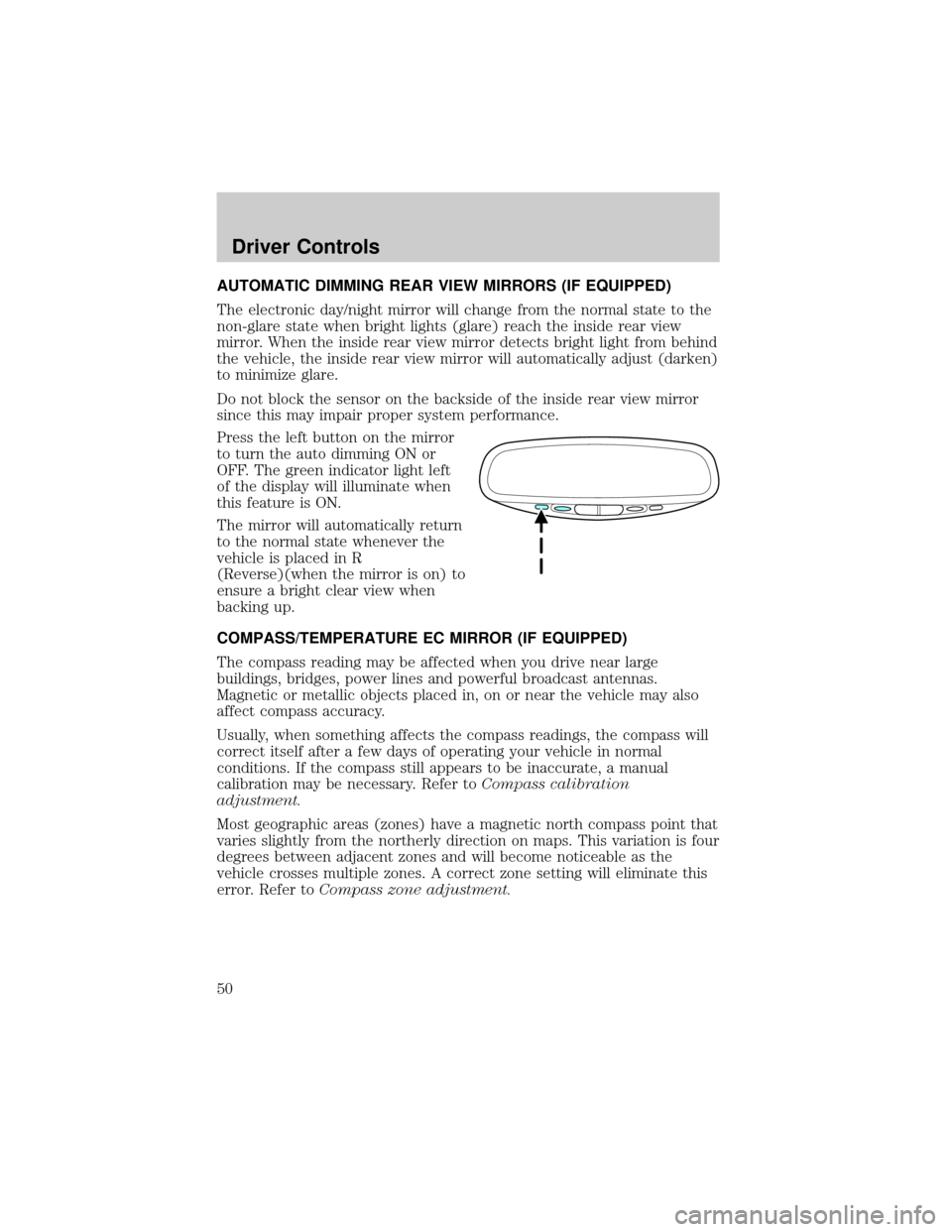
Press the left button on the mirror
to turn the auto dimming ON or
OFF. The green indicator light left
of the display will illuminate when
this feature is ON.
The mirror will automatically return
to the normal state whenever the
vehicle is placed in R
(Reverse)(when the mirror is on) to
ensure a bright clear view when
backing up.
COMPASS/TEMPERATURE EC MIRROR (IF EQUIPPED)
The compass reading may be affected when you drive near large
buildings, bridges, power lines and powerful broadcast antennas.
Magnetic or metallic objects placed in, on or near the vehicle may also
affect compass accuracy.
Usually, when something affects the compass readings, the compass will
correct itself after a few days of operating your vehicle in normal
conditions. If the compass still appears to be inaccurate, a manual
calibration may be necessary. Refer toCompass calibration
adjustment.
Most geographic areas (zones) have a magnetic north compass point that
varies slightly from the northerly direction on maps. This variation is four
degrees between adjacent zones and will become noticeable as the
vehicle crosses multiple zones. A correct zone setting will eliminate this
error. Refer toCompass zone adjustment.
Driver Controls
50
Page 53 of 248

POWER MIRROR CONTROL (IF EQUIPPED)
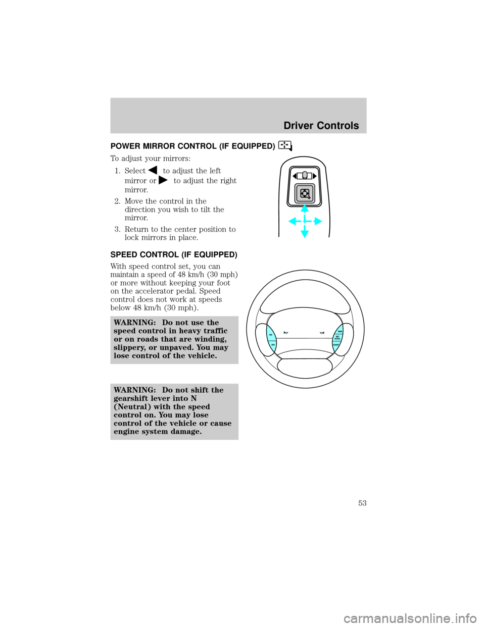
To adjust your mirrors:
1. Select
to adjust the left
mirror or
to adjust the right
mirror.
2. Move the control in the
direction you wish to tilt the
mirror.
3. Return to the center position to
lock mirrors in place.
SPEED CONTROL (IF EQUIPPED)
With speed control set, you can
maintain a speed of 48 km/h (30 mph)
or more without keeping your foot
on the accelerator pedal. Speed
control does not work at speeds
below 48 km/h (30 mph).
WARNING: Do not use the
speed control in heavy traffic
or on roads that are winding,
slippery, or unpaved. You may
lose control of the vehicle.
WARNING: Do not shift the
gearshift lever into N
(Neutral) with the speed
control on. You may lose
control of the vehicle or cause
engine system damage.
Driver Controls
53
Page 57 of 248

CENTER CONSOLE (IF EQUIPPED)
Your vehicle may be equipped with a
variety of console features. These
include:
²Utility compartment with
cassette/compact disc storage
²Cupholders
²Coin holder slots
²Flip up armrest
WARNING: Use only soft cups in the cupholder. Hard objects
can injure you in a collision.
BED EXTENDER (IF EQUIPPED)
Your vehicle may be equipped with a bed extender designed to extend
the pickup box for longer loads.
To extend the bed extender:
1. Lower tailgate.
2. Pull the round knobs on each
side of the extender to release
it from the pickup box.
3. Pivot extender on to the
tailgate.
4. Evenly push down on the
extender and push the round
knobs in on each side locking it
in place.
Green markings on the shaft
indicate the locked position. The
locking clip screws below the middle
bar can be tightened
counterclockwise for extra security.
Driver Controls
57
Page 58 of 248

Note: If the red marking on the shaft is visible, the bed extender
is not locked or properly secured.
To stow the bed extender, follow steps one through four in reverse order.
The bed extender may be used to secure a load of up to 46 kg (100 lbs.)
on the tailgate.
The bed extender should always be kept in the stowed position
with the tailgate closed when not in use.
To remove the bed extender:
1. Extend the bed extender.
2. Pull the round knobs on each
side of the extender to unlock
it.
Make sure the locking clip screws
are loose before removing the
extender.
1. Press the locking clips below
the middle bar on each side and
lift the extender out of the bed.
To install the bed extender, follow the removal procedure in reverse
order.
Driver Controls
58