display MAZDA MODEL CX-5 2022 Owners Manual
[x] Cancel search | Manufacturer: MAZDA, Model Year: 2022, Model line: MODEL CX-5, Model: MAZDA MODEL CX-5 2022Pages: 723, PDF Size: 89.79 MB
Page 394 of 723
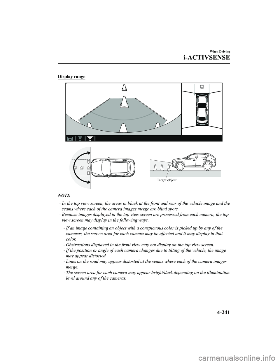
Display range
Target object
NOTE
In the top view screen, the areas in black at the front and rear of the vehicle image and the
seams where each of the camera images merge are blind spots.
Because images displayed in the top view screen are processed from each camera, the top
view screen may display in the following ways.
If an image containing an object with a conspicuous color is picked up by any of the
cameras, the screen area for each camera may be affected and it may display in that
color.
Obstructions displayed in the front view may not display on the top view screen.
If the position or angle of each camera changes due to tilting of the vehicle, the image
may appear distorted.
Lines on the road may appear distorted at the seams where each of the camera images
merge.
The screen area for each camera may appear bright/dark depending on the illumination
level around any of the cameras.
When Driving
i-ACTIVSENSE
4-241
CX-5_8KN5-EA-21K_Edition1_old2021-9-9 8:35:12
Page 395 of 723
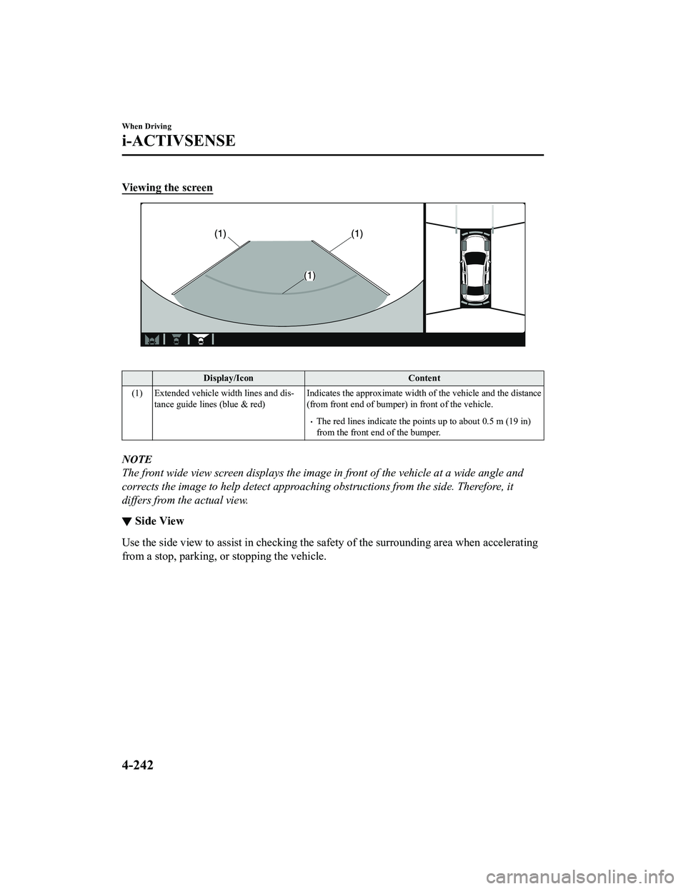
Viewing the screen
Display/IconContent
(1) Extended vehicle width lines and dis ‐
tance guide lines (blue & red) Indicates the approximate width of the vehicle and the distance
(from front end of bumper) in front of the vehicle.
The red lines indicate the points up to about 0.5 m (19 in)
from the front end of the bumper.
NOTE
The front wide view screen displays the imag
e in front of the vehicle at a wide angle and
corrects the image to help detect approaching obstructions from the side. Therefore, it
differs from the actual view.
▼ Side View
Use the side view to assist in checking the safety of the surrounding area when accelerating
from a stop, parking, or stopping the vehicle.
When Driving
i-ACTIVSENSE
4-242
CX-5_8KN5-EA-21K_Edition1_old
2021-9-9 8:35:12
Page 396 of 723
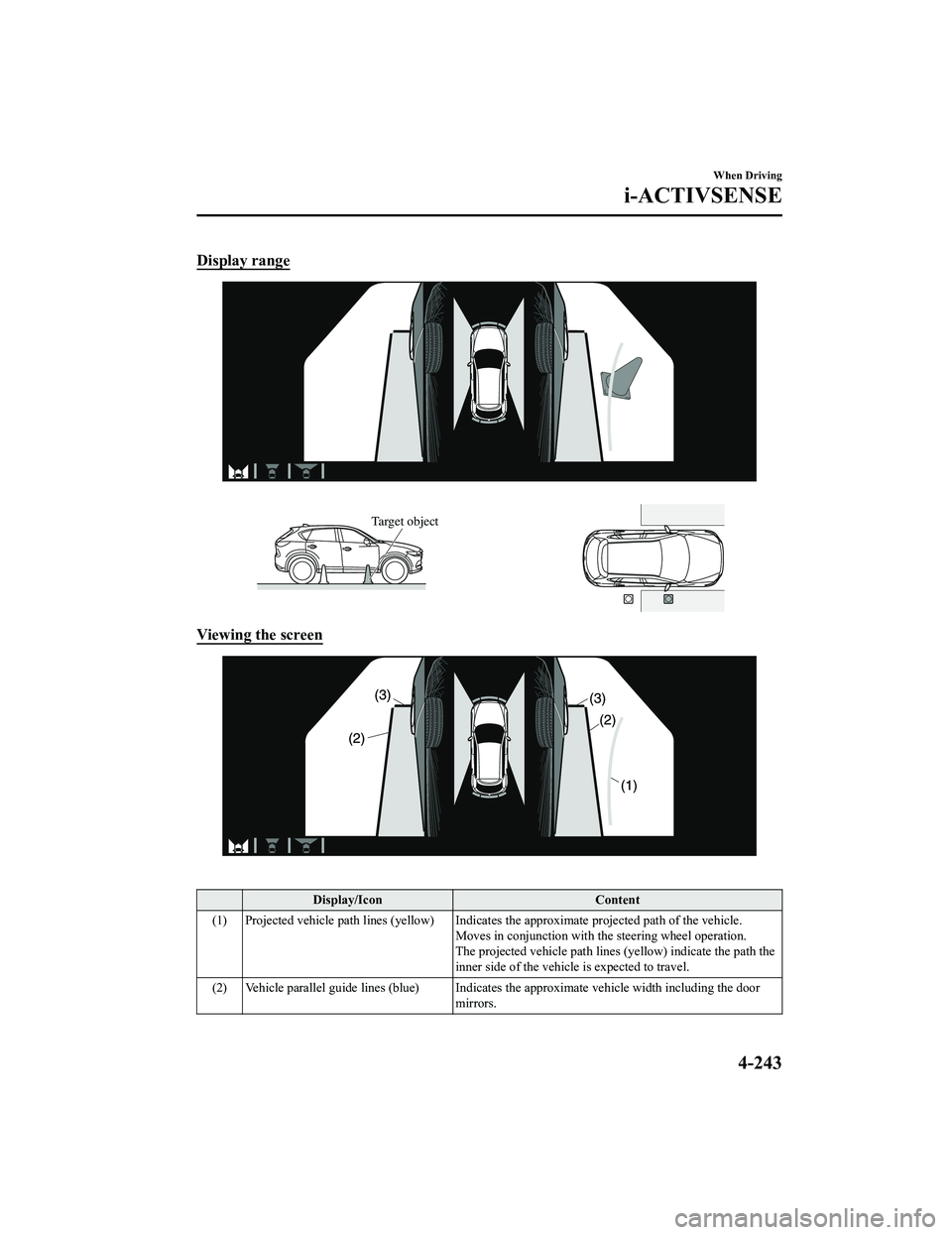
Display range
Target object
Viewing the screen
Display/IconContent
(1) Projected vehicle path lines (yellow) Indicates the approximate projected path of the vehicle. Moves in conjunction with the steering wheel operation.
The projected vehicle path lines (yellow) indicate the path the
inner side of the vehicle is expected to travel.
(2) Vehicle parallel guide lines (blue) Indicates the approximate vehicle width including the door
mirrors.
When Driving
i-ACTIVSENSE
4-243
CX-5_8KN5-EA-21K_Edition1_old 2021-9-9 8:35:12
Page 397 of 723
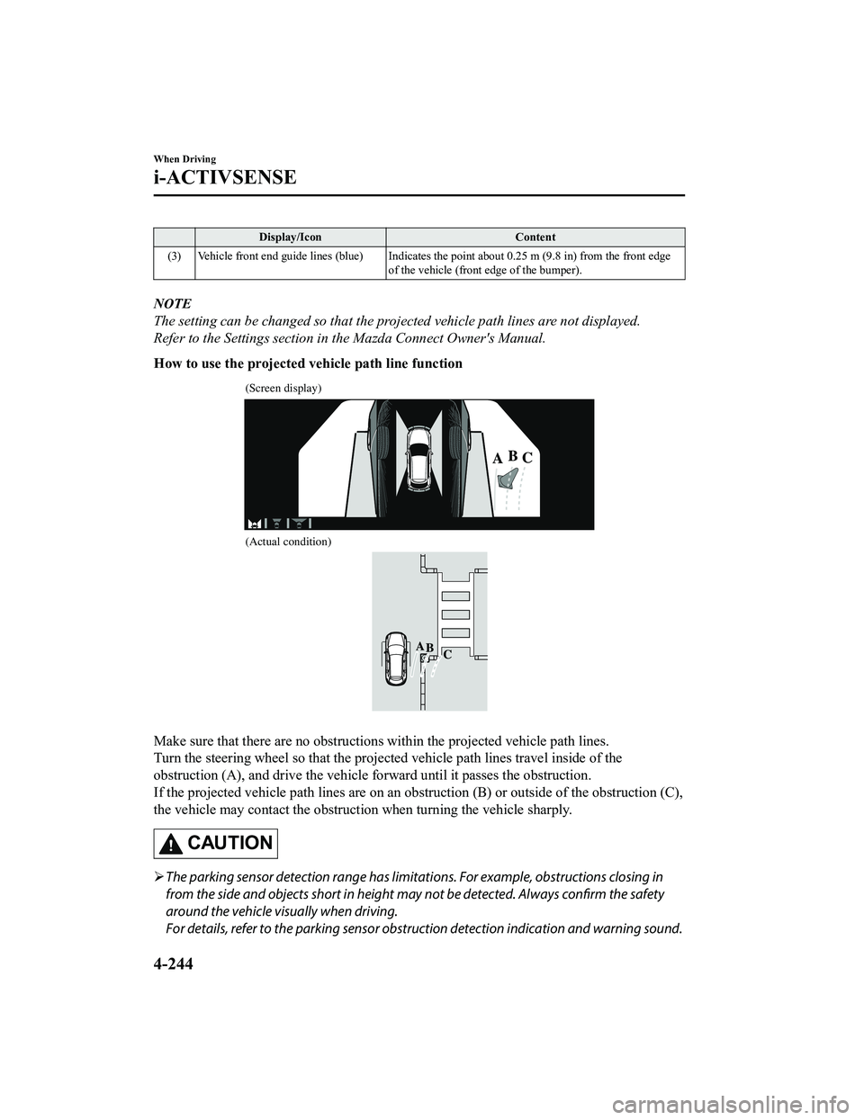
Display/IconContent
(3) Vehicle front end guide lines (blue) Indicates th e point about 0.25 m (9.8 in) from the front edge
of the vehicle (front edge of the bumper).
NOTE
The setting can be changed so that the projected vehicle path lines are not displayed.
Refer to the Settings section in the Mazda Connect Owner's Manual.
How to use the projected vehicle path line function
(Screen display)
(Actual condition)
Make sure that there are no obstructions within the projected vehicle path lines.
Turn the steering wheel so that the projected vehicle path lines travel inside of the
obstruction (A), and drive the vehicle fo rward until it passes the obstruction.
If the projected vehicle path lines are on an ob struction (B) or outside of the obstruction (C),
the vehicle may contact the obstruction when turning the vehicle sharply.
CAUTION
The parking sensor detection range has limitat ions. For example, obstructions closing in
from the side and objects short in height ma y not be detected. Always confirm the safety
around the vehicle visually when driving.
For details, refer to the parking sensor obstru ction detection indication and warning sound.
When Driving
i-ACTIVSENSE
4-244
CX-5_8KN5-EA-21K_Edition1_old 2021-9-9 8:35:12
Page 398 of 723
Refer to Parking Sensor System on page 4-302.
Do not turn the steering wheel any more until the vehicle has passed the obstruction, even
if the obstruction is not visible on the side vi ew image. If the steering wheel is turned even
more, the vehicle may contact the obstruction if it is turned sharply.
NOTE
Because there might be a difference between the image displayed on the screen and the
actual conditions, always check the safety of the surrounding area using the mirrors and
directly with your eyes when driving.
Even though the object displayed on the screen, such as a road curb or a division line of a
parking space, and the vehicle parallel guide lines appear parallel, they may not actually
be parallel.
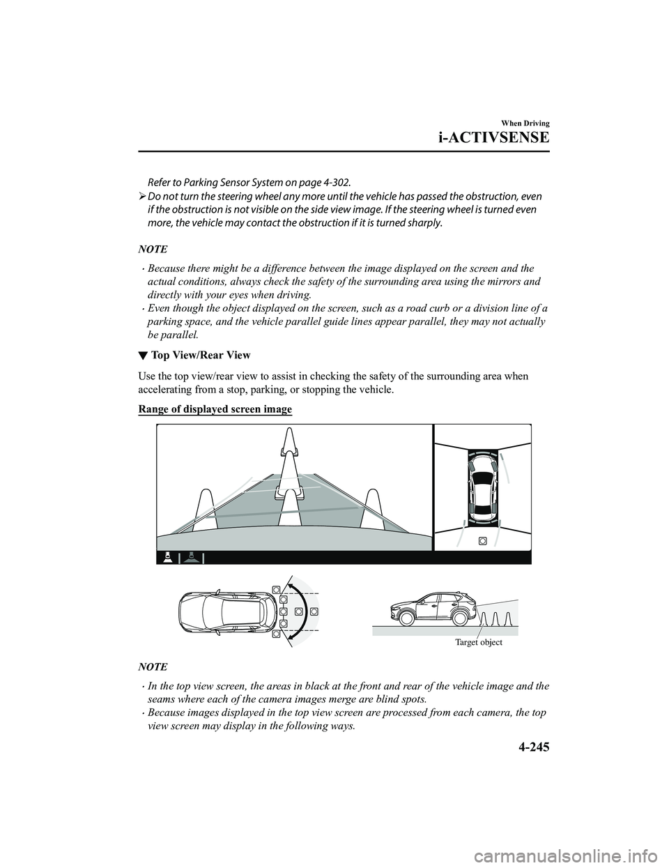
▼ Top View/Rear View
Use the top view/rear view to assist in chec
king the safety of the surrounding area when
accelerating from a stop, parking, or stopping the vehicle.
Range of displayed screen image
Target object
NOTE
In the top view screen, the areas in black at the front and rear of the vehicle image and the
seams where each of the camera images merge are blind spots.
Because images displayed in the top view screen are processed from each camera, the top
view screen may display in the following ways.
When Driving
i-ACTIVSENSE
4-245
CX-5_8KN5-EA-21K_Edition1_old 2021-9-9 8:35:12
Page 399 of 723
If an image containing an object with a conspicuous color is picked up by any of the
cameras, the screen area for each camera may be affected and it may display in that
color.
Obstructions displayed in the rear view may not display on the top view screen.
If the position or angle of each camera changes due to tilting of the vehicle, the image
may appear distorted.
Lines on the road may appear distorted at the seams where each of the camera images
merge.
The screen area for each camera may appear bright/dark depending on the illumination
level around any of the cameras.
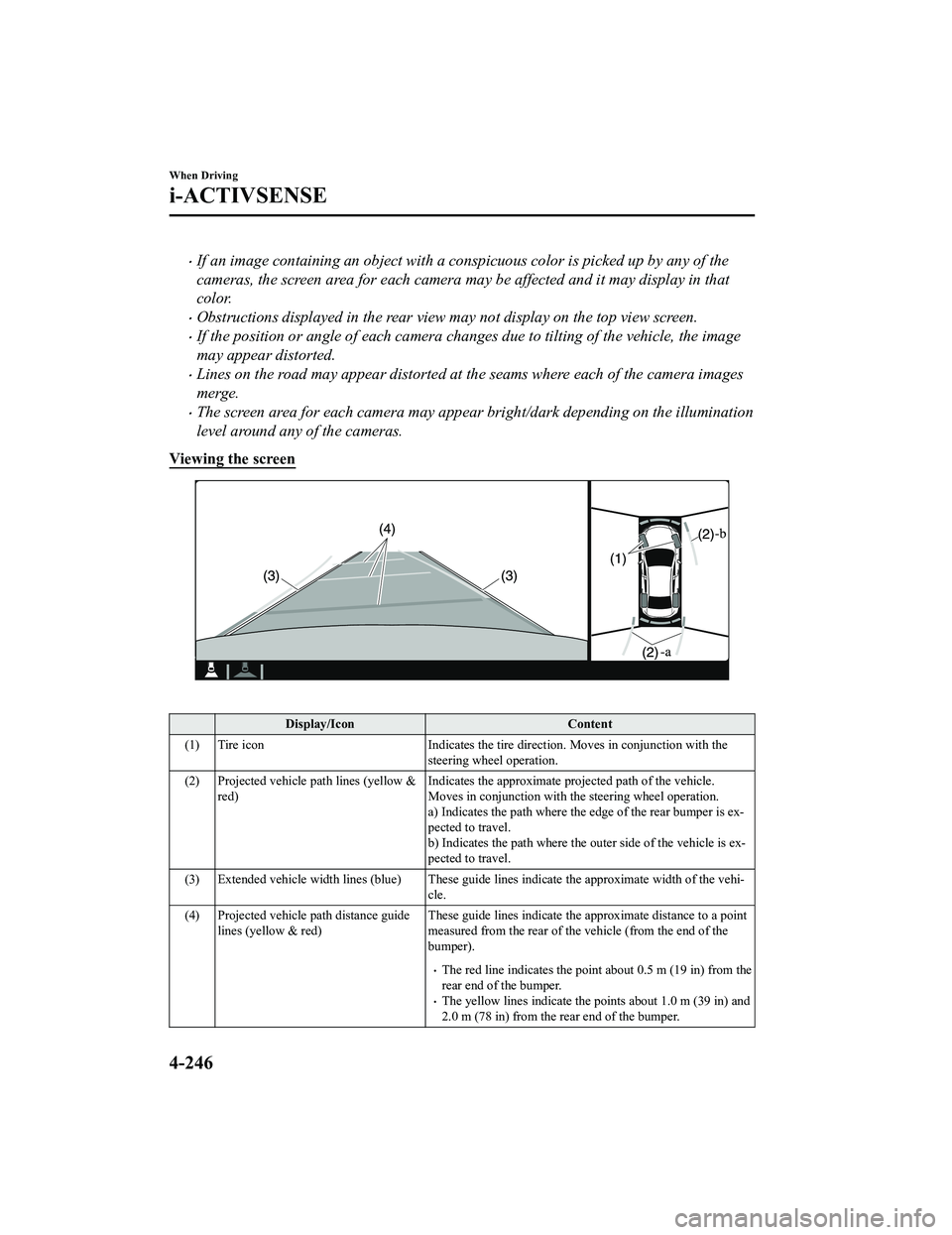
Viewing the screen
Display/Icon Content
(1) Tire icon Indicates the tire direction. Moves in conjunction with the
steering wheel operation.
(2) Projected vehicle path lines (yellow & red) Indicates the approximate projected path of the vehicle.
Moves in conjunction with th
e steering wheel operation.
a) Indicates the path where the edge of the rear bumper is ex ‐
pected to travel.
b) Indicates the path where the outer side of the vehicle is ex ‐
pected to travel.
(3) Extended vehicle width lines (blue) These guide lines indicate the approximate width of the vehi‐
cle.
(4) Projected vehicle path distance guide lines (yellow & red) These guide lines indicate the ap
proximate distance to a point
measured from the rear of th e vehicle (from the end of the
bumper).
The red line indicates the point about 0.5 m (19 in) from the
rear end of the bumper.
The yellow lines indicate the po ints about 1.0 m (39 in) and
2.0 m (78 in) from the rear end of the bumper.
When Driving
i-ACTIVSENSE
4-246
CX-5_8KN5-EA-21K_Edition1_old 2021-9-9 8:35:12
Page 400 of 723
NOTE
The setting can be changed so that the projected vehicle path lines are not displayed.
Refer to the Settings section in the Mazda Connect Owner's Manual.
How to use the projected vehicle path line function
CAUTION
The front of the vehicle swings out wide wh en turning the steering wheel while reversing.
Maintain sufficient distance betwee n the vehicle and an obstruction.
The parking sensor detection range has limita tions. For example, obstructions closing in
from the side and objects short in height may not be detected. Always confirm the safety
around the vehicle vi sually when driving.
For details, refer to the parking sensor obstruction detection indication and warning sound.
Refer to Parking Sensor System on page 4-302.
NOTE
Because there might be a difference between the image displayed on the screen, such as
indicated in the following, and the actual conditions when parking, always check the
safety at the rear of the vehicle and the surrounding area directly with your eyes.
Even though the back end of the parking space (or garage) displayed on the screen and
distance guide lines appear parallel, they may not actually be parallel.
When parking in a space with a division line on only one side of the parking space, even
though the division line and the vehicle widt h guide line appear parallel, they may not
actually be parallel.
The following shows an example of vehicle parking with the steering wheel turned to the
left while backing up the vehicle. When backing into a parking space from the opposite
direction, the steering operation is reversed.
When Driving
i-ACTIVSENSE
4-247
CX-5_8KN5-EA-21K_Edition1_old 2021-9-9 8:35:12
Page 401 of 723
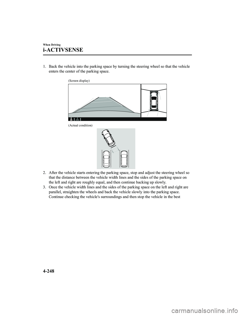
1. Back the vehicle into the parking space by turning the steering wheel so that the vehicleenters the center of the parking space.
(Screen display)
(Actual condition)
2. After the vehicle starts entering the parking space, stop and adjust the steering wheel sothat the distance between the vehicle width lines and the sides of the parking space on
the left and right are roughly equal, and then continue backing up slowly.
3. Once the vehicle width lines and the sides of the parking space on the left and right are parallel, straighten the wheels and back the vehicle slowly into the parking space.
Continue checking the vehicle's surroundings and then stop the vehicle in the best
When Driving
i-ACTIVSENSE
4-248
CX-5_8KN5-EA-21K_Edition1_old 2021-9-9 8:35:12
Page 402 of 723
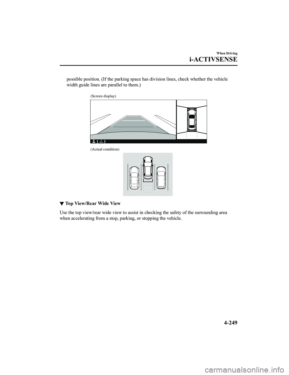
possible position. (If the parking space has division lines, check whether the vehicle
width guide lines are parallel to them.)
(Screen display)
(Actual condition)
▼Top View/Rear Wide View
Use the top view/rear wide view to assist in checking the safety of the surrounding area
when accelerating from a stop, pa
rking, or stopping the vehicle.
When Driving
i-ACTIVSENSE
4-249
CX-5_8KN5-EA-21K_Edition1_old 2021-9-9 8:35:12
Page 403 of 723
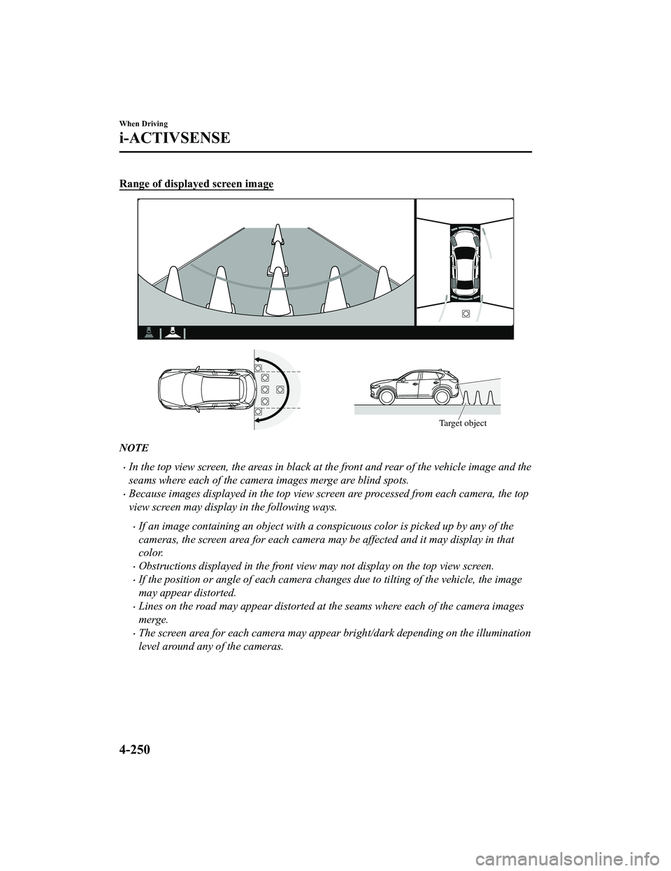
Range of displayed screen image
Target object
NOTE
In the top view screen, the areas in black at the front and rear of the vehicle image and the
seams where each of the camera images merge are blind spots.
Because images displayed in the top view screen are processed from each camera, the top
view screen may display in the following ways.
If an image containing an object with a conspicuous color is picked up by any of the
cameras, the screen area for each camera may be affected and it may display in that
color.
Obstructions displayed in the front view may not display on the top view screen.
If the position or angle of each camera changes due to tilting of the vehicle, the image
may appear distorted.
Lines on the road may appear distorted at the seams where each of the camera images
merge.
The screen area for each camera may appear bright/dark depending on the illumination
level around any of the cameras.
When Driving
i-ACTIVSENSE
4-250
CX-5_8KN5-EA-21K_Edition1_old 2021-9-9 8:35:12