bumper MAZDA MODEL CX-9 2021 Owner's Manual
[x] Cancel search | Manufacturer: MAZDA, Model Year: 2021, Model line: MODEL CX-9, Model: MAZDA MODEL CX-9 2021Pages: 723, PDF Size: 10.61 MB
Page 379 of 723

If the camera is subjected to excessive changes in temperature such as by pouring hot
water on the camera during cold weather, the 360°View Monitor may not operate
normally.
If the battery voltage is low, the screen might be temporarily difficult to view, however,
this does not indicate a problem.
The 360°View Monitor has limitations. Objects under the bumper or near both ends of the
bumper cannot be displayed.
Obstructions above the upper image range of the camera are not displayed.
Under the following conditions, the screen mi ght be difficult to view, however this does
not indicate a problem.
The temperature near the lens is high/low.
Rainy conditions, water droplets on the camera, or high humidity.
Mud or foreign matter near the camera.
Extremely bright light such as sunlight or headlights hitting the camera lens directly.
The surroundings are illuminated by vehicle lights, fluorescent lights, or LED lights
(display may flicker).
Extremely small dark or white dots appear on the screen (dots may flicker).
Because the 360°View Monitor camera uses a special lens, the distance displayed on the
screen differs from the actual distance.
Obstructions displayed on the screen may appear differently than in actuality.
(Obstructions may appear fallen, larger, or longer than they actually are.)
Do not apply stickers to a camera or the area around it. In addition, do not install
accessories or an illuminated number/character license plate to the area around a
camera. Otherwise, the camera may not correctly display the surrounding conditions.
Images displayed on the monitor from the 360° view monitor camera are reversed images
(mirror images).
Free/open source software information
This product includes free/open sources. Information about the licensing and source code
is available at the following URL.
https://www.denso.com/global/en/opensource/svss/mazda/
When Driving
i-ACTIVSENSE
4-210
CX-9_8JK1-EA-20G_Edition6_old 2021-12-8 9:30:44
Page 387 of 723

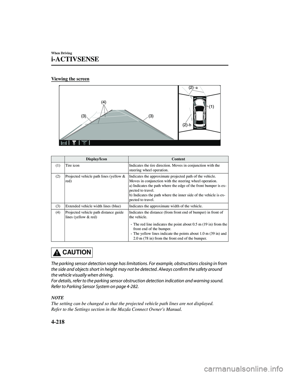
Viewing the screen
Display/IconContent
(1) Tire icon Indicates the tire direction. Moves in conjunction with the
steering wheel operation.
(2) Projected vehicle path lines (yellow & red) Indicates the approx
imate projected path of the vehicle.
Moves in conjunction with the steering wheel operation.
a) Indicates the path where the edge of the front bumper is ex ‐
pected to travel.
b) Indicates the path where the inner side of the vehicle is ex‐
pected to travel.
(3) Extended vehicle width lines (blue) Indicat es the approximate width of the vehicle.
(4) Projected vehicle path distance guide lines (yellow & red) Indicates the distance (from fron
t end of bumper) in front of
the vehicle.
The red line indicates the poin t about 0.5 m (19 in) from the
front end of the bumper.
The yellow lines indicate the po ints about 1.0 m (39 in) and
2.0 m (78 in) from the front end of the bumper.
CAUTION
The parking sensor detection range has limitation s. For example, obstructions closing in from
the side and objects short in height may not be detected. Always confirm the safety around
the vehicle visually when driving.
For details, refer to the parking sensor obstru ction detection indication and warning sound.
Refer to Parking Sensor System on page 4-282.
NOTE
The setting can be changed so that the projected vehicle path lines are not displayed.
Refer to the Settings section in the Mazda Connect Owner's Manual.
When Driving
i-ACTIVSENSE
4-218
CX-9_8JK1-EA-20G_Edition6_old 2021-12-8 9:30:44
Page 390 of 723

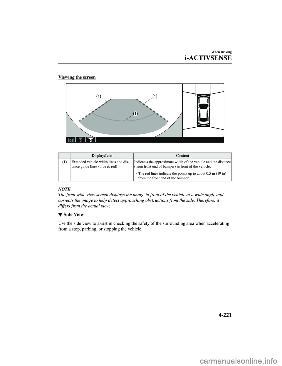
Viewing the screen
Display/IconContent
(1) Extended vehicle width lines and dis ‐
tance guide lines (blue & red) Indicates the approximate width
of the vehicle and the distance
(from front end of bumper) in front of the vehicle.
The red lines indicate the points up to about 0.5 m (19 in)
from the front end of the bumper.
NOTE
The front wide view screen displays the image in front of the vehicle at a wide angle and
corrects the image to help detect approaching obstructions from the side. Therefore, it
differs from the actual view.
▼ Side View
Use the side view to assist in checking the sa
fety of the surrounding area when accelerating
from a stop, parking, or stopping the vehicle.
When Driving
i-ACTIVSENSE
4-221
CX-9_8JK1-EA-20G_Edition6_old 2021-12-8 9:30:44
Page 392 of 723

Display/IconContent
(3) Vehicle front end guide lines (blue) Indicates th e point about 0.25 m (9.8 in) from the front edge
of the vehicle (front edge of the bumper).
NOTE
The setting can be changed so that the projected vehicle path lines are not displayed.
Refer to the Settings section in the Mazda Connect Owner's Manual.
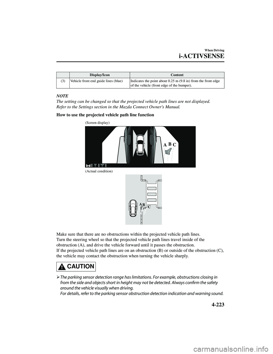
How to use the projected vehicle path line function
(Screen display)
(Actual condition)
Make sure that there are no obstructions within the projected vehicle path lines.
Turn the steering wheel so that the projected vehicle path lines travel inside of the
obstruction (A), and drive the vehicle forward until it passes the obstruction.
If the projected vehicle path lines are on an obs truction (B) or outside of the obstruction (C),
the vehicle may contact the obstruction when turning the vehicle sharply.
CAUTION
The parking sensor detection range has limita tions. For example, obstructions closing in
from the side and objects short in height may not be detected. Always confirm the safety
around the vehicle vi sually when driving.
For details, refer to the parking sensor obstruction detection indication and warning sound.
When Driving
i-ACTIVSENSE
4-223
CX-9_8JK1-EA-20G_Edition6_old 2021-12-8 9:30:44
Page 394 of 723

If an image containing an object with a conspicuous color is picked up by any of the
cameras, the screen area for each camera may be affected and it may display in that
color.
Obstructions displayed in the rear view may not display on the top view screen.
If the position or angle of each camera changes due to tilting of the vehicle, the image
may appear distorted.
Lines on the road may appear distorted at the seams where each of the camera images
merge.
The screen area for each camera may appear bright/dark depending on the illumination
level around any of the cameras.
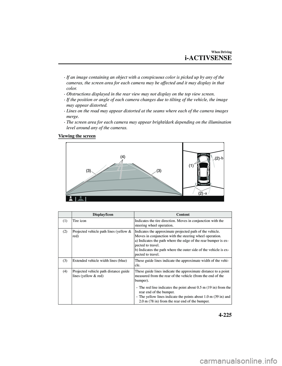
Viewing the screen
Display/Icon Content
(1) Tire icon Indicates the tire direction. Moves in conjunction with the
steering wheel operation.
(2) Projected vehicle path lines (yellow & red) Indicates the approximate proj
ected path of the vehicle.
Moves in conjunction with the steering wheel operation.
a) Indicates the path where the edge of the rear bumper is ex ‐
pected to travel.
b) Indicates the path where the outer side of the vehicle is ex ‐
pected to travel.
(3) Extended vehicle width lines (blue) These guide lines indicate the approximate width of the vehi‐
cle.
(4) Projected vehicle path distance guide lines (yellow & red) These guide lines indicate the ap
proximate distance to a point
measured from the rear of the vehicle (from the end of the
bumper).
The red line indicates the poin t about 0.5 m (19 in) from the
rear end of the bumper.
The yellow lines indicate the poi nts about 1.0 m (39 in) and
2.0 m (78 in) from the rear end of the bumper.
When Driving
i-ACTIVSENSE
4-225
CX-9_8JK1-EA-20G_Edition6_old 2021-12-8 9:30:44
Page 399 of 723

Viewing the screen
Display/IconContent
(1) Extended vehicle width lines and dis ‐
tance guide lines (blue & red) These guide lines indicate the
approximate width of the vehi‐
cle and distance to a point measur ed from the rear of the vehi‐
cle (from the end of the bumper).
The red lines indicate the points up to about 0.5 m (19 in)
from the rear end of the bumper.
NOTE
The top view/rear wide view screen displays the image at the rear of the vehicle at a wide
angle and corrects the image to help detect approaching obstructions from the side.
Therefore, it differs from the actual view.
▼ Margin of Error Between
Road Surface on Screen and Actual Road Surface
There might be some margin of error between the road surface appearing on the screen and
the actual road surface. A margin of error in the perceived distance could lead to an
accident, therefore be aware of the followin g conditions which can more easily produce
errors in the perceived distance.
The vehicle tilts due to weight of passengers and cargo.
If the vehicle is tilted, obstructions picked up by a camera can appear farther or closer than
the actual distance from the vehicle.
When Driving
i-ACTIVSENSE
4-230
CX-9_8JK1-EA-20G_Edition6_old 2021-12-8 9:30:44
Page 410 of 723

Do not use the front bumper to push other vehicles or obstructions such as when pulling
out of a parking space. Otherwise, the radar sensor (front) could be hit and its position
deviated.
Do not remove, disassemble, or mo dify the radar sensor (front).
For repairs, replacement or paint work ar ound the radar sensor (front), consult an
Authorized Mazda Dealer.
Do not modify the suspension. If the suspensi on are modified, the vehicle's posture could
change and the radar sensor (front) may not be able to correctly detect a vehicle ahead or
an obstruction.
NOTE
Under the following conditions, the radar sensor (front) may not be able to detect vehicles
ahead or obstructions correctly and each system may not operate normally.
The rear surface of a vehicle ahead does not reflect radio waves effectively, such as an
unloaded trailer or an automobile with a loading platform covered by a soft top,
vehicles with a hard plastic tailgate, and round-shaped vehicles.
Vehicles ahead with low vehicle height and thus less area for reflecting radio waves.
Visibility is reduced due to a vehicle ahead casting off water, snow, or sand from its tires
and onto your windshield.
The luggage compartment is loaded with heavy objects or the rear passenger seats are
occupied.
Ice, snow, or soiling is on the front surface of the front emblem.
During inclement weather such as rain, snow, or sand storms.
When driving near facilities or objects emitting strong radio waves.
Under the following conditions, the radar sensor (front) may not be able to detect vehicles
ahead or obstructions.
The beginning and end of a curve.
Roads with continuous curves.
Narrow lane roads due to road construction or lane closures.
The vehicle ahead enters the radar sensor's blind spot.
The vehicle ahead is running abnormally due to accident or vehicle damage.
Roads with repeated up and down slopes
Driving on poor roads or unpaved roads.
The distance between your vehicle and the vehicle ahead is extremely short.
A vehicle suddenly comes close such as by cutting into the lane.
To prevent incorrect operation of the system, use tires of the same specified size,
manufacturer, brand, and tread pattern on all four wheels. In addition, do not use tires
with significantly different wear patterns or tire pressures on the same vehicle (Including
the temporary spare tire).
If the battery power is weak, the system may not operate correctly.
When Driving
i-ACTIVSENSE
4-241
CX-9_8JK1-EA-20G_Edition6_old 2021-12-8 9:30:44
Page 412 of 723

Radar Sensors (Rear)*
Your vehicle is equipped with radar sensors (rear). The following systems also use the radar
sensors (rear).
Blind Spot Monitoring (BSM)
Rear Cross Traffic Alert (RCTA)
The radar sensors (rear) function by detecting the radio waves reflected off a vehicle
approaching from the rear or an obstruction sent from the radar sensor.
Radar sensors (rear)
The radar sensors (rear) are installed inside the rear bumper, one each on the left and right
sides.
Always keep the surface of the rear bumper near the radar sensors (rear) clean so that the
radar sensors (rear) operate normally. Also, do not apply items such as stickers.
Refer to Exterior Care on page 6-52.
CAUTION
If the rear bumper receives a severe impact, the system may no longer operate normally. Stop
the system immediately and have the vehicle inspected at an Authorized Mazda Dealer.
NOTE
The detection ability of the radar sensors (rear) has limitations. In the following cases,
the detection ability may lower and the system may not operate normally.
The rear bumper near the radar sensors (rear) has become deformed.
Snow, ice or mud adheres to the radar sensors (rear) on the rear bumper.
Under bad weather conditions such as rain, snow and fog.
Under the following conditions, the radar sensors (rear) cannot detect target objects or it
may be difficult to detect them.
Stationary objects on a road or a road side such as small, two-wheeled vehicles,
bicycles, pedestrians, animals, and shopping carts.
When Driving
i-ACTIVSENSE
*Some models.4-243
CX-9_8JK1-EA-20G_Edition6_old 2021-12-8 9:30:44
Page 413 of 723

Vehicle shapes which do not reflect radar waves well such as empty trailers with a low
vehicle height and sports cars.
Vehicles are shipped with the direction of the radar sensors (rear) adjusted for each
vehicle to a loaded vehicle condition so that the radar sensors (rear) detect approaching
vehicles correctly. If the direction of the radar sensors (rear) has deviated for some
reason, have the vehicle inspected at an Authorized Mazda Dealer.
For repairs or replacement of the radar sensors (rear), or bumper repairs, paintwork, and
replacement near the radar sensors, consult an Authorized Mazda Dealer.
Turn off the system while pulling a trailer or while an accessory such as a bicycle carrier
is installed to the rear of the vehicle. Otherwise, the radio waves emitted by the radar will
be blocked causing the system to not operate normally.
The radar sensors are regulated by the relevant radio wave laws of the country in which
the vehicle is driven. If the vehicle is driven abroad, authorization from the country in
which the vehicle is driven may be required.
When Driving
i-ACTIVSENSE
4-244
CX-9_8JK1-EA-20G_Edition6_old 2021-12-8 9:30:44
Page 414 of 723

Ultrasonic Sensor (Rear)*
The ultrasonic sensors (rear) function by emitting ultrasonic waves which are reflected off
obstructions at the rear and the returning ultrasonic waves are picked up by the ultrasonic
sensors (rear).
Ultrasonic sensor (rear)
The ultrasonic sensors (rear) are mounted in the rear bumper.
When Driving
i-ACTIVSENSE
*Some models.4-245
CX-9_8JK1-EA-20G_Edition6_old2021-12-8 9:30:44