ECU MAZDA MODEL MAZDASPEED 3 2009 (in English) Service Manual
[x] Cancel search | Manufacturer: MAZDA, Model Year: 2009, Model line: MODEL MAZDASPEED 3, Model: MAZDA MODEL MAZDASPEED 3 2009Pages: 412, PDF Size: 6.18 MB
Page 226 of 412
![MAZDA MODEL MAZDASPEED 3 2009 (in English) Service Manual Black plate (226,1)
NOTE
Master code:
The Master Code is used to initialize or re-
initialize the ID code in the event that the code
is not set to [0000] and/or the personalized ID
code is not known. MAZDA MODEL MAZDASPEED 3 2009 (in English) Service Manual Black plate (226,1)
NOTE
Master code:
The Master Code is used to initialize or re-
initialize the ID code in the event that the code
is not set to [0000] and/or the personalized ID
code is not known.](/img/28/15590/w960_15590-225.png)
Black plate (226,1)
NOTE
Master code:
The Master Code is used to initialize or re-
initialize the ID code in the event that the code
is not set to [0000] and/or the personalized ID
code is not known. The initialization process
resets the ID code to [0000]. The master code
can potentially defeat the intent of the security
of the parental lock if it is located by persons
not authorized by the owner to access certain
channels.
SIRIUS Satellite Radio Master Code: [0913]
(How to clear the message)lPress any of the following FM/AM,
SAT, CD, MEDIA, CAT, ESN/DISP,
Instant replay, POWER buttons.
lTurn the ACC off or insert a CD.lChange a channel.
NOTE
lWhen a numeric value other than the
master code is input and the scan button is
pressed, “SR1 Err ”is displayed and then it
returns to the “SR1---- ”display again.
lIf an ID code is not input for 10 seconds,
“Err ”is displayed and it returns to the
former display.
lChannel preset buttons 1, 2, 3, 4 and the
scan button are used for inputting the ID
code. Buttons 5 and 6 cannot be used.
Change of ID code
Setting condition: SAT mode
When changing the ID code, the new ID
code is input after the previous one is
input first.
(Registered ID code input)
1. Hold the scan button, then press channel preset button 5, hold both
buttons together for 1.5 seconds. 2.
“ENTER PIN ”appears for 2 seconds
which indicates that it is in code input
mode.
3. “SR1 - - - - ”appears, which indicates
that it is ready for code input.
4. Input the registered ID code using channel preset buttons 1-4. Then press
the scan button.
Example: When the registered ID code
is“2323 ”, input “2323 ”. At this time
“ SR1 2323 ”is displayed.
Press 1 for the first digit, 2 for the
second, 3 for the third, and 4 for the
last digit. For example, if your number
is 2323, press 1 three times, 2 four
times, 3 three, and 4 four times. If the
display goes off while inputting, begin
from Step 1.
NOTE
The registered ID code is the default [0000] at
the time of factory shipment. If [0000] results
in “Err ”on the display, go to the
“ INITIALIZATION OF ID CODE” section to
reset to [0000].
(Verification with the registered ID
code)
5. Determine the input code by pressing the scan button briefly.
6. If it does not match with the previously registered code, “SR1 Err ”is displayed
and then it returns to “SR1 - - - - ”.
7. If it matches with the previously registered code, “ENTER PIN ”appears
again and it switches to code input
mode.
8. “SR1 - - - - ”appears, and it is ready for
input of the new ID code.
6-42
Interior Comfort
Audio System
Mazda3_8Z87-EA-08F_Edition1 Page226
Monday, May 19 2008 9:57 AM
Form No.8Z87-EA-08F
Page 243 of 412
Black plate (243,1)
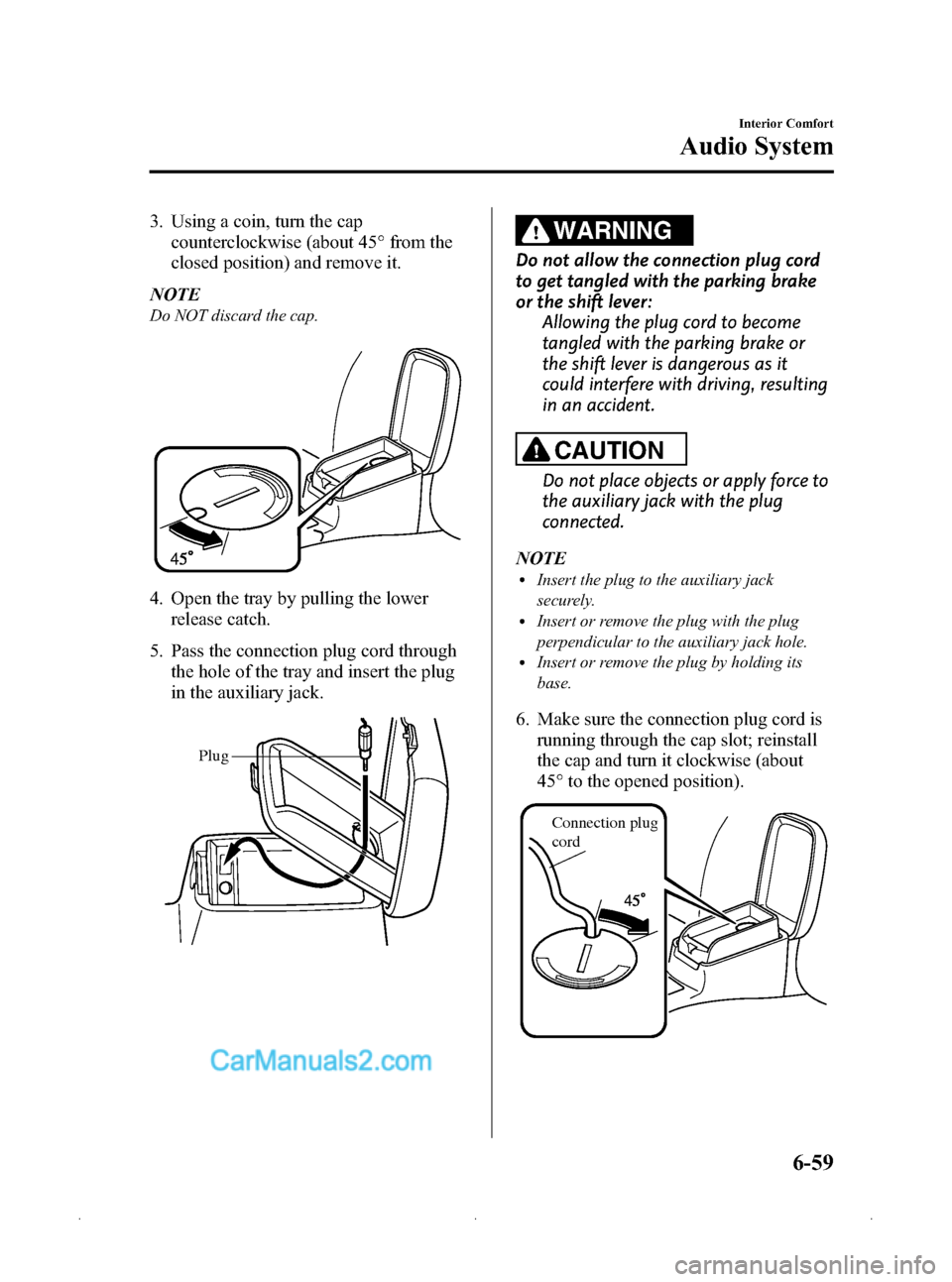
3. Using a coin, turn the capcounterclockwise (about 45° from the
closed position) and remove it.
NOTE
Do NOT discard the cap.
4. Open the tray by pulling the lower release catch.
5. Pass the connection plug cord through the hole of the tray and insert the plug
in the auxiliary jack.
Plug
WARNING
Do not allow the connection plug cord
to get tangled with the parking brake
or the shift lever: Allowing the plug cord to become
tangled with the parking brake or
the shift lever is dangerous as it
could interfere with driving, resulting
in an accident.
CAUTION
Do not place objects or apply force to
the auxiliary jack with the plug
connected.
NOTE
lInsert the plug to the auxiliary jack
securely.
lInsert or remove the plug with the plug
perpendicular to the auxiliary jack hole.
lInsert or remove the plug by holding its
base.
6. Make sure the connection plug cord is running through the cap slot; reinstall
the cap and turn it clockwise (about
45° to the opened position).
Connection plug
cord
Interior Comfort
Audio System
6-59
Mazda3_8Z87-EA-08F_Edition1 Page243
Monday, May 19 2008 9:58 AM
Form No.8Z87-EA-08F
Page 257 of 412
Black plate (257,1)
qCenter Console
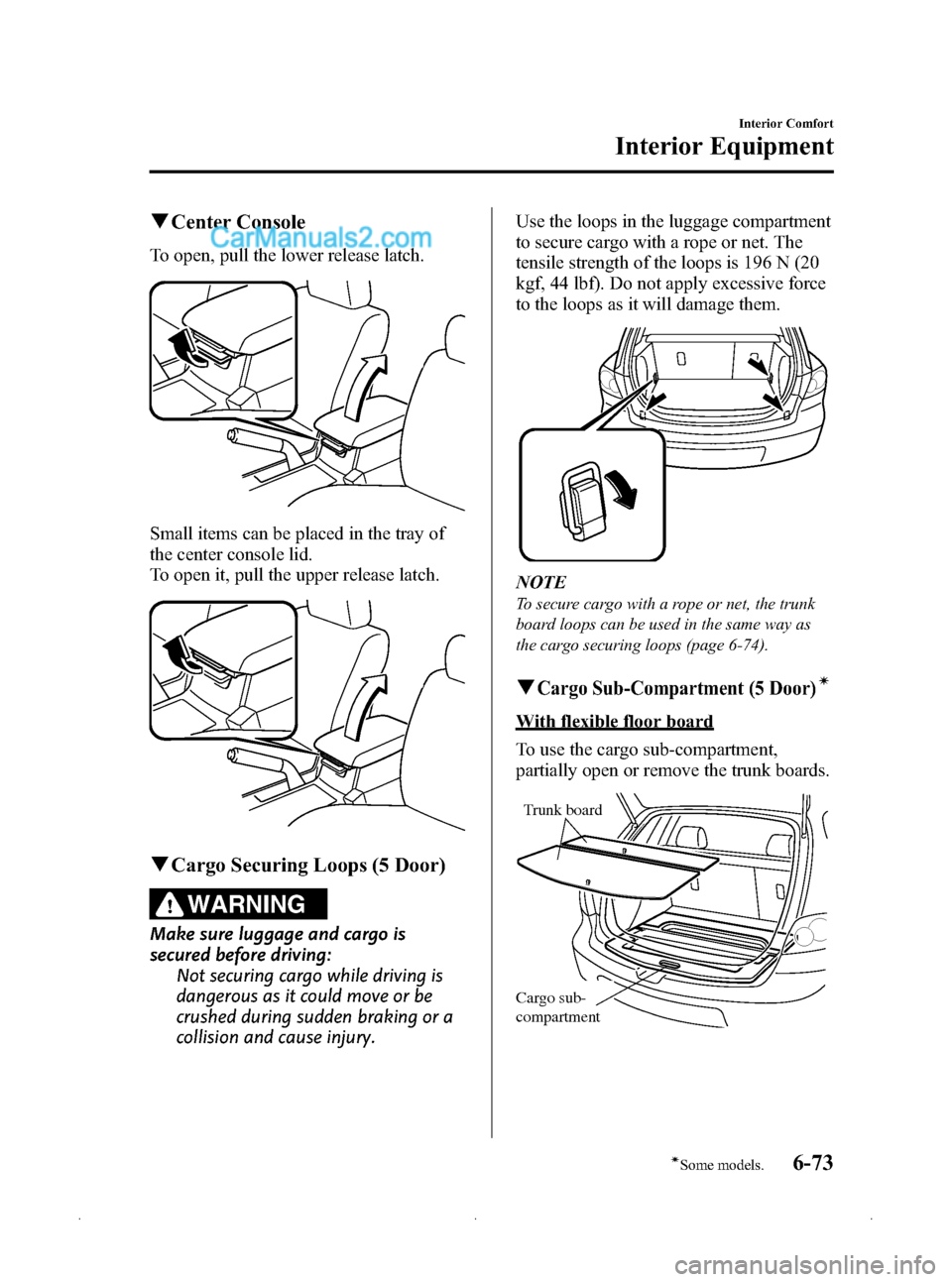
To open, pull the lower release latch.
Small items can be placed in the tray of
the center console lid.
To open it, pull the upper release latch.
qCargo Securing Loops (5 Door)
WARNING
Make sure luggage and cargo is
secured before driving:
Not securing cargo while driving is
dangerous as it could move or be
crushed during sudden braking or a
collision and cause injury. Use the loops in the luggage compartment
to secure cargo with a rope or net. The
tensile strength of the loops is 196 N (20
kgf, 44 lbf). Do not apply excessive force
to the loops as it will damage them.
NOTE
To secure cargo with a rope or net, the trunk
board loops can be used in the same way as
the cargo securing loops (page 6-74).
qCargo Sub-Compartment (5 Door)í
With flexible floor board
To use the cargo sub-compartment,
partially open or remove the trunk boards.
Trunk board
Cargo sub-
compartment
Interior Comfort
Interior Equipment
6-73íSome models.
Mazda3_8Z87-EA-08F_Edition1 Page257
Monday, May 19 2008 9:58 AM
Form No.8Z87-EA-08F
Page 258 of 412

Black plate (258,1)
Without flexible floor board
To use the cargo sub-compartment,
remove or lift the trunk board.
Cargo sub-
compartmentTrunk board
q
Flexible Floor Board (5 Door)í
The luggage compartment can be
separated vertically and/or horizontally,
using the trunk board and the trunk board
loops.
CAUTION
Make sure the trunk board is firmly
secured when it is fitted into the
trunk board loops. If it is not firmly
secured, it could unexpectedly
disengage causing damage to the
trunk board loops or the trunk
board. NOTE
The trunk board loops can be used in the same
way as the cargo securing loops. The tensile
strength of the loops is 147 N (15 kgf, 33 lbf).
Do not apply excessive force to the trunk board
loops as it will damage them (page 6-73).
Compartment
divider loops
Rear trunk board Front trunk board
To separate vertically
Use the rear trunk board to separate the
luggage compartment vertically.
1. Pull the trunk board loops out.
Compartment
divider loop
6-74
Interior Comfort
íSome models.
Interior Equipment
Mazda3_8Z87-EA-08F_Edition1 Page258
Monday, May 19 2008 9:58 AM
Form No.8Z87-EA-08F
Page 259 of 412

Black plate (259,1)
2. Insert the trunk board loops into thetrunk board slits.
Front
Trunk
board
NOTE
To facilitate insertion of the trunk board loops
into the trunk board slits, first insert the
bottom of the rear trunk board into the groove
of the luggage sub-compartment.
GrooveCargo sub-
compartment
3. Rock the trunk board to make sure the
board is installed securely.
To separate horizontally
Use the front trunk board to separate the
luggage compartment horizontally.
CAUTION
ØDo not place heavy objects on the
trunk board or apply excessive
force as they could damage the
trunk board. The permissible
weight is about 5 kg (11 lb).
Ø Do not use the rear trunk board to
separate the luggage
compartment horizontally. The
rear trunk board cannot be locked
to the trunk board loops and it
could move and cause injury while
the vehicle is moving.
1. Pull the trunk board loops out.
Compartment
divider loop
2. Insert the trunk board loop into slit A.
Slit A
Interior Comfort
Interior Equipment
6-75
Mazda3_8Z87-EA-08F_Edition1 Page259
Monday, May 19 2008 9:58 AM
Form No.8Z87-EA-08F
Page 260 of 412
Black plate (260,1)
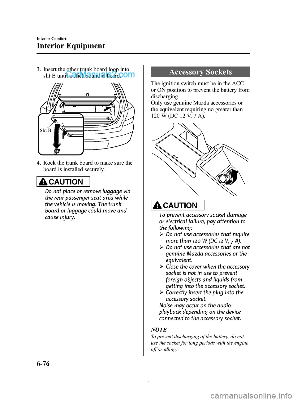
3. Insert the other trunk board loop intoslit B until a click sound is heard.
Slit B
4. Rock the trunk board to make sure the
board is installed securely.
CAUTION
Do not place or remove luggage via
the rear passenger seat area while
the vehicle is moving. The trunk
board or luggage could move and
cause injury.
Accessory Sockets
The ignition switch must be in the ACC
or ON position to prevent the battery from
discharging.
Only use genuine Mazda accessories or
the equivalent requiring no greater than
120 W (DC 12 V, 7 A).
CAUTION
To prevent accessory socket damage
or electrical failure, pay attention to
the following:
ØDo not use accessories that require
more than 120 W (DC 12 V, 7 A).
Ø Do not use accessories that are not
genuine Mazda accessories or the
equivalent.
Ø Close the cover when the accessory
socket is not in use to prevent
foreign objects and liquids from
getting into the accessory socket.
Ø Correctly insert the plug into the
accessory socket.
Noise may occur on the audio
playback depending on the device
connected to the accessory socket.
NOTE
To prevent discharging of the battery, do not
use the socket for long periods with the engine
off or idling.
6-76
Interior Comfort
Interior Equipment
Mazda3_8Z87-EA-08F_Edition1 Page260
Monday, May 19 2008 9:58 AM
Form No.8Z87-EA-08F
Page 267 of 412
Black plate (267,1)
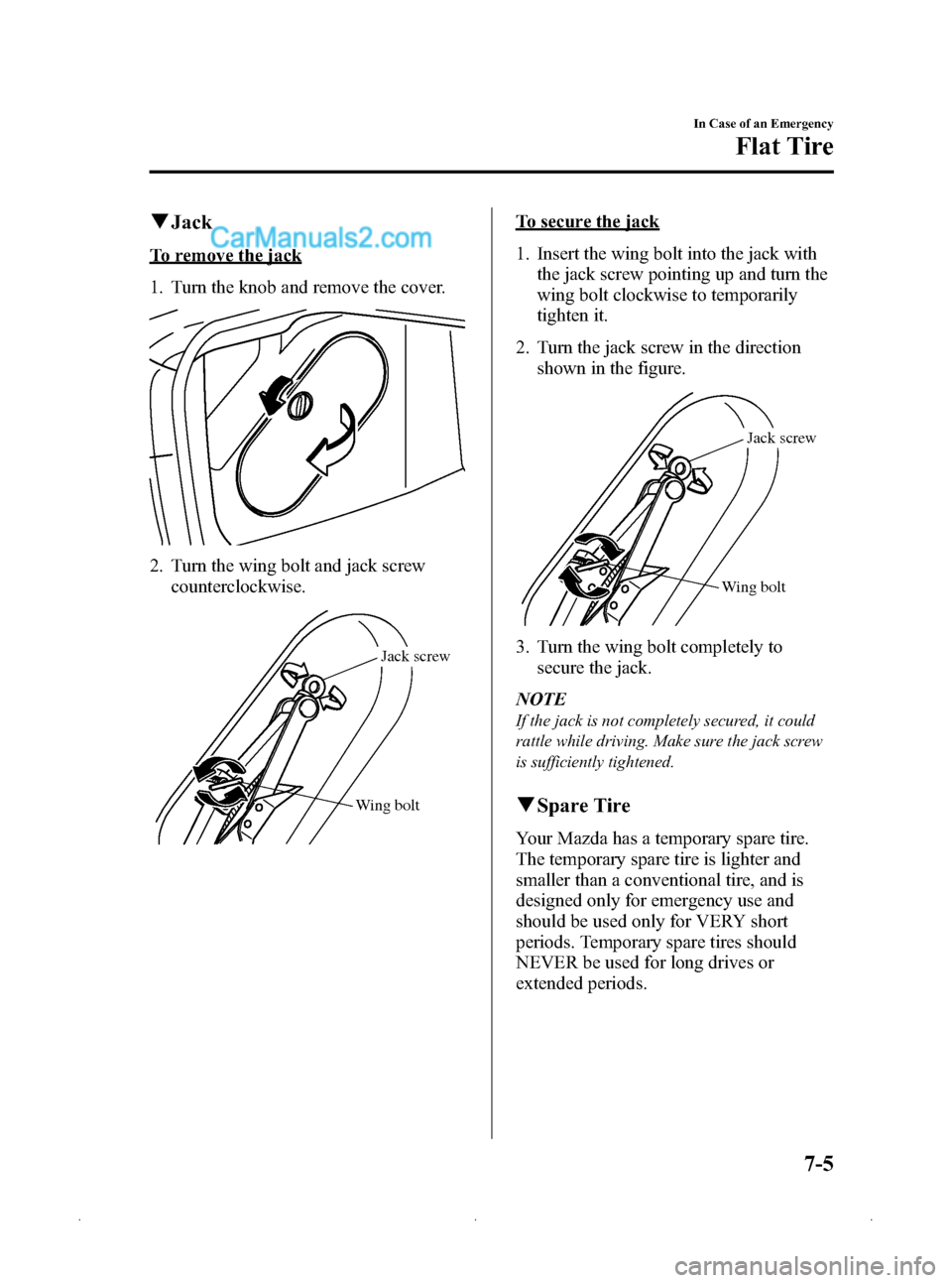
qJack
To remove the jack
1. Turn the knob and remove the cover.
2. Turn the wing bolt and jack screw
counterclockwise.
Wing bolt Jack screw
To secure the jack
1. Insert the wing bolt into the jack with
the jack screw pointing up and turn the
wing bolt clockwise to temporarily
tighten it.
2. Turn the jack screw in the direction shown in the figure.
Wing bolt Jack screw
3. Turn the wing bolt completely to
secure the jack.
NOTE
If the jack is not completely secured, it could
rattle while driving. Make sure the jack screw
is sufficiently tightened.
q Spare Tire
Your Mazda has a temporary spare tire.
The temporary spare tire is lighter and
smaller than a conventional tire, and is
designed only for emergency use and
should be used only for VERY short
periods. Temporary spare tires should
NEVER be used for long drives or
extended periods.
In Case of an Emergency
Flat Tire
7-5
Mazda3_8Z87-EA-08F_Edition1 Page267
Monday, May 19 2008 9:58 AM
Form No.8Z87-EA-08F
Page 274 of 412
Black plate (274,1)
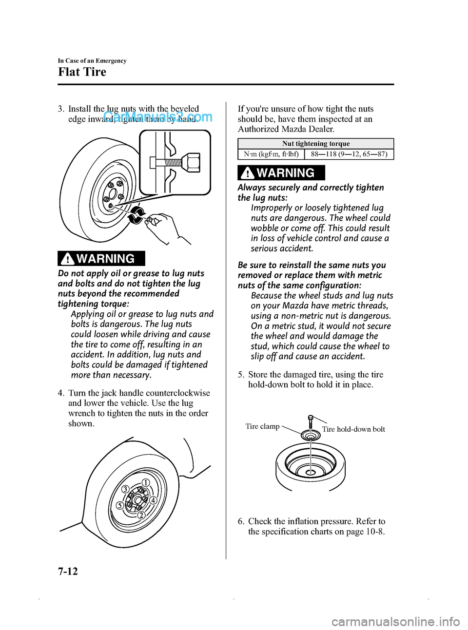
3. Install the lug nuts with the bevelededge inward; tighten them by hand.
WARNING
Do not apply oil or grease to lug nuts
and bolts and do not tighten the lug
nuts beyond the recommended
tightening torque: Applying oil or grease to lug nuts and
bolts is dangerous. The lug nuts
could loosen while driving and cause
the tire to come off, resulting in an
accident. In addition, lug nuts and
bolts could be damaged if tightened
more than necessary.
4. Turn the jack handle counterclockwise and lower the vehicle. Use the lug
wrench to tighten the nuts in the order
shown.
If you're unsure of how tight the nuts
should be, have them inspected at an
Authorized Mazda Dealer.
Nut tightening torque
N·m (kgf·m, ft·lbf) 88 ―118 (9 ―12, 65 ―87)
WARNING
Always securely and correctly tighten
the lug nuts:
Improperly or loosely tightened lug
nuts are dangerous. The wheel could
wobble or come off. This could result
in loss of vehicle control and cause a
serious accident.
Be sure to reinstall the same nuts you
removed or replace them with metric
nuts of the same configuration: Because the wheel studs and lug nuts
on your Mazda have metric threads,
using a non-metric nut is dangerous.
On a metric stud, it would not secure
the wheel and would damage the
stud, which could cause the wheel to
slip off and cause an accident.
5. Store the damaged tire, using the tire hold-down bolt to hold it in place.
Tire clamp Tire hold-down bolt
6. Check the inflation pressure. Refer to
the specification charts on page 10-8.
7-12
In Case of an Emergency
Flat Tire
Mazda3_8Z87-EA-08F_Edition1 Page274
Monday, May 19 2008 9:58 AM
Form No.8Z87-EA-08F
Page 281 of 412
Black plate (281,1)
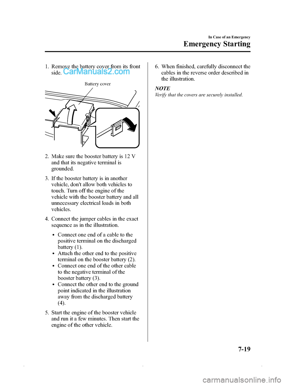
1. Remove the battery cover from its frontside.
Battery cover
2. Make sure the booster battery is 12 V
and that its negative terminal is
grounded.
3. If the booster battery is in another vehicle, don't allow both vehicles to
touch. Turn off the engine of the
vehicle with the booster battery and all
unnecessary electrical loads in both
vehicles.
4. Connect the jumper cables in the exact sequence as in the illustration.
lConnect one end of a cable to the
positive terminal on the discharged
battery (1).
lAttach the other end to the positive
terminal on the booster battery (2).
lConnect one end of the other cable
to the negative terminal of the
booster battery (3).
lConnect the other end to the ground
point indicated in the illustration
away from the discharged battery
(4).
5. Start the engine of the booster vehicle and run it a few minutes. Then start the
engine of the other vehicle. 6. When finished, carefully disconnect the
cables in the reverse order described in
the illustration.
NOTE
Verify that the covers are securely installed.
In Case of an Emergency
Emergency Starting
7-19
Mazda3_8Z87-EA-08F_Edition1 Page281
Monday, May 19 2008 9:58 AM
Form No.8Z87-EA-08F
Page 285 of 412
Black plate (285,1)
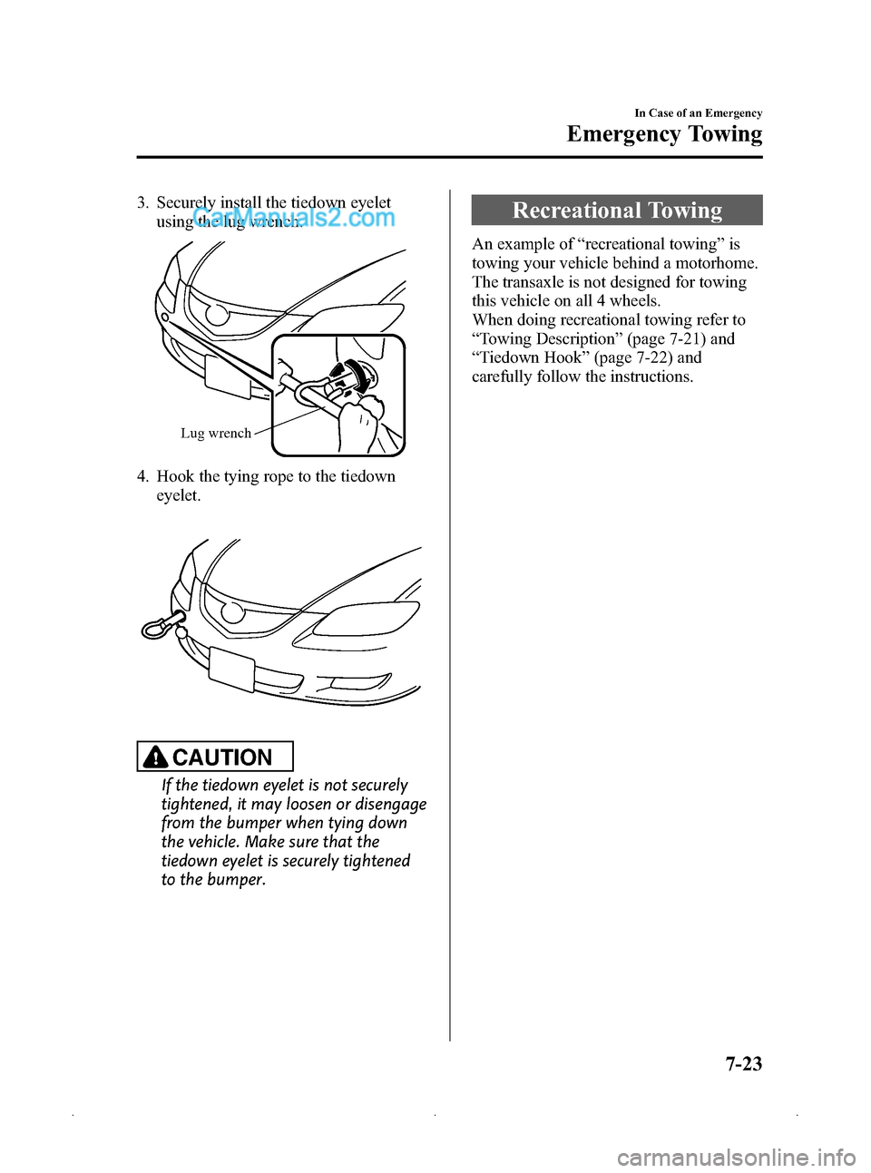
3. Securely install the tiedown eyeletusing the lug wrench.
Lug wrench
4. Hook the tying rope to the tiedown
eyelet.
CAUTION
If the tiedown eyelet is not securely
tightened, it may loosen or disengage
from the bumper when tying down
the vehicle. Make sure that the
tiedown eyelet is securely tightened
to the bumper.
Recreational Towing
An example of “recreational towing ”is
towing your vehicle behind a motorhome.
The transaxle is not designed for towing
this vehicle on all 4 wheels.
When doing recreational towing refer to
“ Towing Description ”(page 7-21) and
“ Tiedown Hook ”(page 7-22) and
carefully follow the instructions.
In Case of an Emergency
Emergency Towing
7-23
Mazda3_8Z87-EA-08F_Edition1 Page285
Monday, May 19 2008 9:58 AM
Form No.8Z87-EA-08F