clock MAZDA MODEL TRIBUTE 2004 Owners Manual (in English)
[x] Cancel search | Manufacturer: MAZDA, Model Year: 2004, Model line: MODEL TRIBUTE, Model: MAZDA MODEL TRIBUTE 2004Pages: 256, PDF Size: 2.64 MB
Page 26 of 256
Random play in CD mode
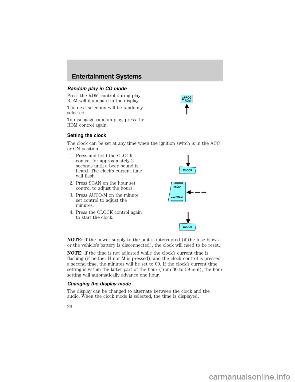
Press the RDM control during play.
RDM will illuminate in the display.
The next selection will be randomly
selected.
To disengage random play, press the
RDM control again.
Setting the clock
The clock can be set at any time when the ignition switch is in the ACC
or ON position.
1. Press and hold the CLOCK
control for approximately 2
seconds until a beep sound is
heard. The clock's current time
will flash.
2. Press SCAN on the hour set
control to adjust the hours.
3. Press AUTO-M on the minute
set control to adjust the
minutes.
4. Press the CLOCK control again
to start the clock.
NOTE:If the power supply to the unit is interrupted (if the fuse blows
or the vehicle's battery is disconnected), the clock will need to be reset.
NOTE:If the time is not adjusted while the clock's current time is
flashing (if neither H nor M is pressed), and the clock control is pressed
a second time, the minutes will be set to 00. If the clock's current time
setting is within the latter part of the hour (from 30 to 59 min), the hour
setting will automatically advance one hour.
Changing the display mode
The display can be changed to alternate between the clock and the
audio. When the clock mode is selected, the time is displayed.
Entertainment Systems
26
Page 27 of 256
Press the CLOCK control to
alternate the display.
NOTE:If the audio operation is selected while the clock mode is on, the
selected audio mode will be displayed for ten seconds, then the display
will revert to the clock mode.
AM/FM RADIO WITH CASSETTE TAPE AND COMPACT DISC
PLAYER/CHANGER (IN-DASH CD CHANGER)
Volume/power control
Ensure that the ignition is either in the ACC or ON position for the audio
system to function.
Press the control to turn the audio
system on or off.
Entertainment Systems
27
Page 39 of 256
Multiple ejection
1. Press and hold the CD eject
control for approximately 2
seconds until a beep sound is
heard.
2. Wait approximately 5 seconds or
press the CD eject control again within 5 seconds after the beep is
heard.
3. Remove the CD. The next CD will then be ejected.
NOTE:
²CDs will be ejected in numerical order, lowest number first.
²All CDs in the tray will be ejected continuously.
²CDs can be ejected when the ignition switch is OFF. Press and hold
the CD eject control for approximately 2 seconds and all CDs will
eject.
Random play
The random play feature works in CD mode and plays the selections on
the current CD in random order.
Random play in CD mode
Press the RDM control during play.
RDM will illuminate in the display.
The next selection will be randomly
selected.
To disengage random play, press the
RDM control again.
Setting the clock
The clock can be set at any time when the ignition switch is in the ACC
or ON position.
1. Press and hold the CLOCK
control for approximately 2
seconds until a beep sound is
heard. The clock's current time
will flash.
Entertainment Systems
39
Page 40 of 256
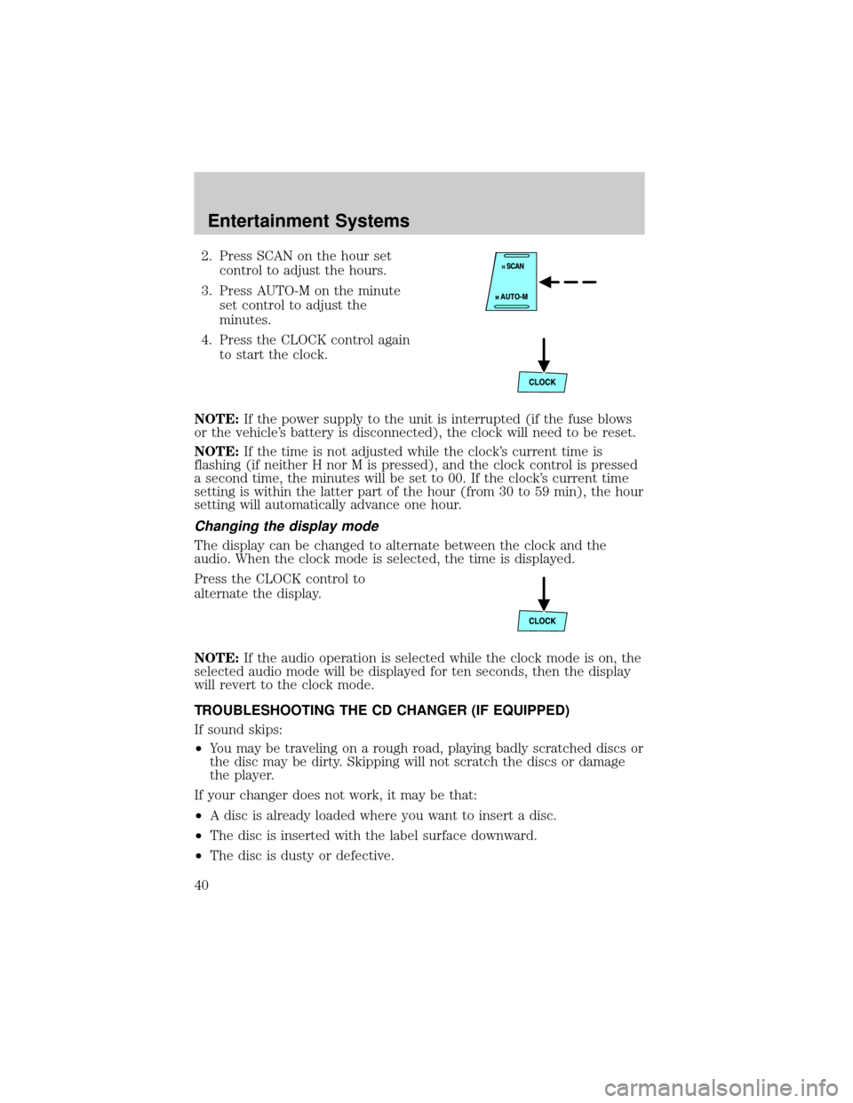
2. Press SCAN on the hour set
control to adjust the hours.
3. Press AUTO-M on the minute
set control to adjust the
minutes.
4. Press the CLOCK control again
to start the clock.
NOTE:If the power supply to the unit is interrupted (if the fuse blows
or the vehicle's battery is disconnected), the clock will need to be reset.
NOTE:If the time is not adjusted while the clock's current time is
flashing (if neither H nor M is pressed), and the clock control is pressed
a second time, the minutes will be set to 00. If the clock's current time
setting is within the latter part of the hour (from 30 to 59 min), the hour
setting will automatically advance one hour.
Changing the display mode
The display can be changed to alternate between the clock and the
audio. When the clock mode is selected, the time is displayed.
Press the CLOCK control to
alternate the display.
NOTE:If the audio operation is selected while the clock mode is on, the
selected audio mode will be displayed for ten seconds, then the display
will revert to the clock mode.
TROUBLESHOOTING THE CD CHANGER (IF EQUIPPED)
If sound skips:
²You may be traveling on a rough road, playing badly scratched discs or
the disc may be dirty. Skipping will not scratch the discs or damage
the player.
If your changer does not work, it may be that:
²A disc is already loaded where you want to insert a disc.
²The disc is inserted with the label surface downward.
²The disc is dusty or defective.
Entertainment Systems
40
Page 54 of 256

Replacing brake/tail/turn/backup lamps bulbs
The brake/tail/turn/backup lamp bulbs are located in the tail lamp
assembly, one just below the other. Follow the same steps to replace
either bulb:
1. Open the liftgate to expose the
lamp assemblies.
2. Remove the two screws from
the lamp assembly.
3. Carefully remove the lamp
assembly by pulling it rearward.
4. Twist the bulb socket
counterclockwise and remove
from lamp assembly.
5. Pull the bulb straight out of the
socket and push in the new
bulb.
6. To complete installation, follow
the removal procedure in
reverse order.
Replacing front parking/turn signal lamp bulbs
1. Make sure that the headlamp control is in the OFF position.
2. Open the hood. The position lamps are located on the bottom half of
each headlamp.
3. Disconnect the electrical connector from the bulb by pulling
rearward.
4. Remove the bulb socket from the lamp assembly by turning
counterclockwise.
Lights
54
Page 55 of 256

5. Pull the bulb straight out of the
socket and push in the new
bulb.
6. To complete installation, follow
the removal procedure in
reverse order.
Replacing fog lamp bulbs (if equipped)
1. Remove the bulb socket from
the fog lamp by turning
counterclockwise.
2.
Disconnect the electrical
connector from the fog lamp bulb.
3. Connect the electrical connector to the new fog lamp bulb.
4. Install the bulb socket in the fog lamp turning clockwise.
WARNING: Handle a halogen headlamp bulb carefully and keep
out of children's reach. Grasp the bulb only by its plastic base
and do not touch the glass. The oil from your hands could cause
the bulb to break the next time the headlamps are operated.
Always wear safety glasses while handling bulbs.
NOTE: If the bulb is accidentally touched, it should be cleaned with
rubbing alcohol before being used.
Replacing license plate lamp bulbs
1. Remove two screws and the
license plate lamp assembly
(located above the license
plate) from the liftgate.
2. Remove bulb socket from lamp
assembly by turning
counterclockwise.
3.
Pull the bulb out from the socket
and push in the new bulb.
4. Install the bulb socket in lamp
assembly turning it clockwise,
5. Install the lamp assembly on liftgate with two screws.
Replacing high-mount brake lamp bulbs
For bulb replacement, see an authorized Mazda dealer.
Lights
55
Page 63 of 256

To adjust your mirrors:
1. Rotate the control clockwise to
adjust the right mirror and
rotate the control
counterclockwise to adjust the
left mirror.
2. Move the control in the
direction you wish to tilt the
mirror.
3. Return to the center position to lock mirrors in place.
Fold-away mirrors
Pull the side mirrors in carefully
when driving through a narrow
space, like an automatic car wash.
Heated outside mirrors
(if equipped)
Both mirrors are heated
automatically to remove ice, mist
and fog when the rear window
defrost is activated.
Do not remove ice from the
mirrors with a scraper or
attempt to readjust the mirror
glass if it is frozen in place.
These actions could cause damage to the glass and mirrors.
SPEED CONTROL (IF EQUIPPED)
With speed control set, you can maintain a speed of 48 km/h (30 mph)
or more without keeping your foot on the accelerator pedal. Speed
control does not work at speeds below 48 km/h (30 mph).
Driver Controls
63
Page 81 of 256

Adjustable head restraints (if equipped)
The purpose of these head restraints is to help limit head motion in the
event of a rear collision. To properly adjust your head restraints, lift the
head restraint so that it is located directly behind your head or as close
to that position as possible.
The head restraints can be moved
up and down.
Push side control and push down on
head restraint to lower it.
Using the manual lumbar support (if equipped)
The lumbar support control is
located on the inboard side of the
driver's seat.
Turn the lumbar support control
clockwise to increase firmness.
Turn the lumbar support control
counterclockwise to increase
softness.
Seating and Safety Restraints
81
Page 100 of 256
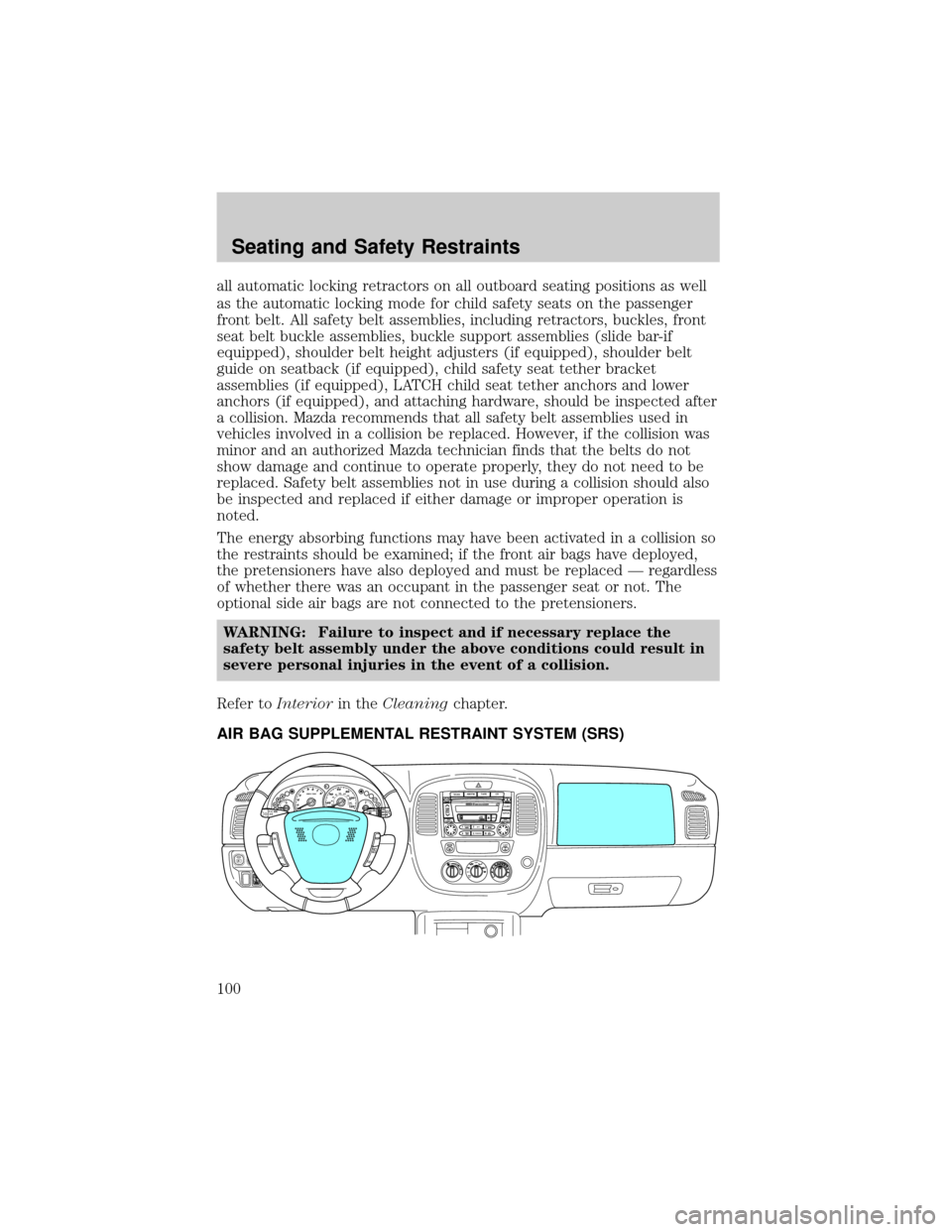
all automatic locking retractors on all outboard seating positions as well
as the automatic locking mode for child safety seats on the passenger
front belt. All safety belt assemblies, including retractors, buckles, front
seat belt buckle assemblies, buckle support assemblies (slide bar-if
equipped), shoulder belt height adjusters (if equipped), shoulder belt
guide on seatback (if equipped), child safety seat tether bracket
assemblies (if equipped), LATCH child seat tether anchors and lower
anchors (if equipped), and attaching hardware, should be inspected after
a collision. Mazda recommends that all safety belt assemblies used in
vehicles involved in a collision be replaced. However, if the collision was
minor and an authorized Mazda technician finds that the belts do not
show damage and continue to operate properly, they do not need to be
replaced. Safety belt assemblies not in use during a collision should also
be inspected and replaced if either damage or improper operation is
noted.
The energy absorbing functions may have been activated in a collision so
the restraints should be examined; if the front air bags have deployed,
the pretensioners have also deployed and must be replaced Ð regardless
of whether there was an occupant in the passenger seat or not. The
optional side air bags are not connected to the pretensioners.
WARNING: Failure to inspect and if necessary replace the
safety belt assembly under the above conditions could result in
severe personal injuries in the event of a collision.
Refer toInteriorin theCleaningchapter.
AIR BAG SUPPLEMENTAL RESTRAINT SYSTEM (SRS)
E CMPH4x4H
F60
408 7 6
5
4
3
2
12020 406080100
120
140
160
18080100
120km/hRPM X 1000
RSM
CST SET
ACCOFF ON
AM/FMTAPE
CD
SCAN
12 3
45 6
LOADCLOCK
AUTO-MPRORPT
RDM/BS TR/APC TR/APC
FF REW
TUNE
SEEKDISCPUSH
POWER VOLP
U
S
H
A
U
D
IO
C
O
N
T
LOCK
A/COFFMAX
A/C
Seating and Safety Restraints
100
Page 160 of 256

Fuse/Relay
LocationFuse Amp
RatingPassenger Compartment Fuse
Panel Description
5 5A ABS unit (EVAC & FILL), ASC
unit, Restraints Control Module
(RCM), ASC main SW to ASC
unit, Clock spring switch
6 10A Flasher unit, Reversing lamps,
Park Aid Module (PAM)
7 10A Passive Anti-theft Transceiver
(PATS), RCM, EEC fuse
8 10A Cluster, Shift lock relay (coil),
O/D signal to PCM, GEM, E/C
autolamp mirror
9 3A PCM relay (coil), Fan relay 1, 2, 3
(coil), A/C relay (coil)
10 20A Front wiper motor, Front washer
motor
11 10A ACC relay (coil), Key interlock
solenoid, GEM
12 5A Radio
13 Ð Not used
14 20A Cigar lighter
15 15A Park lamp relay, Front position
lamps, License lamps, Tail lamps,
Park lamp relay (coil), Trailer
fuse, Illumination fuse
16 10A Cluster, Power mirror, GEM,
Heated seats
17 15A Sun roof motor
18 5A Illumination for: Cluster, Heater
unit, Radio, Hazard switch, Rear
defrost switch, 4WD switch, Front
fog switch
19 10A Subwoofer amp
Roadside Emergencies
160