manual transmission MAZDA MX-5 1994 User Guide
[x] Cancel search | Manufacturer: MAZDA, Model Year: 1994, Model line: MX-5, Model: MAZDA MX-5 1994Pages: 1708, PDF Size: 82.34 MB
Page 510 of 1708

TRANSMISSION K 8. Apply ATF to the new O-rings, and install them onto the manual shaft. 9. Apply ATF to the manual shaft, and install it into the transmission case. 10. Install the parking rod and retaining ring. 11. Apply ATF to the manual plate, and install it onto the manual shaft. 12. Drive the spring pin. 13. Check the parking mechanism operation. 14. Apply ATF to the new seal rings, and install them onto the oil distributor. 15. Install the snap ring, key, and speedometer drive gear onto the output shaft. 16. Secure the speedometer drive gear with the snap ring. Gartner Banana
Page 514 of 1708

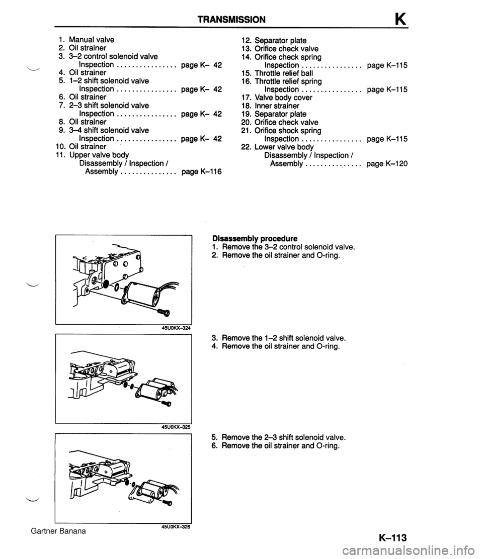
TRANSMISSION 1. Manual valve 12. Separator plate 2. Oil strainer 13. Orifice check valve 3. 3-2 control solenoid valve 14. Orifice check spring ................ ................ i/ Inspection page K- 42 Inspection page K-115 4. Oil strainer 15. Throttle relief ball 5. 1-2 shift solenoid valve 16. Throttle relief spring Inspection ................ page K- 42 Inspection ................ page K-115 6. Oil strainer 17. Valve body cover 7. 2-3 shift solenoid valve 18. Inner strainer Inspection ................ page K- 42 19. Separator plate 8. Oil strainer 20. Orifice check valve 9. 3-4 shift solenoid valve 21. Orifice shock spring ................ Inspection ................ page K- 42 Inspection page K-115 10. Oil strainer 22. Lower valve body 11. Upper valve body Disassembly / Inspection / ................ Disassembly / Inspection / Assembly page K-120 Assembly ............... page K-116 Disassembly procedure 1. Remove the 3-2 control solenoid valve. 2. Remove the oil strainer and O-ring. 3. Remove the 1-2 shift solenoid valve. 4. Remove the oil strainer and O-ring. I I 45UOKX425 5. Remove the 2-3 shift solenoid valve. 6. Remove the oil strainer and O-ring. i/ Gartner Banana
Page 518 of 1708

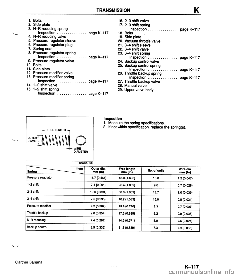
TRANSMISSION 1. Bolts 16. 2-3 shift valve 2. Side plate 17. 2-3 shift spring 3. N-R reducing spring Inspection ................ page K-117 ................ w Inspection page K-117 18. Bolts 4. N-R reducing valve 19. Side plate 5. Pressure regulator sleeve 20. Vacuum throttle valve 6. Pressure regulator plug 21. 3-4 shift sleeve 7. Spring seat 22. 3-4 shift valve 8. Pressure regulator spring 23. 3-4 shift spring Inspection ................ page K-117 Inspection ................ page K-117 9. Pressure regulator valve 24. Backup control valve 10. Bolts 25. Backup control spring 11. Side plate Inspection ................ page K-117 12. Pressure modifier valve 26. Throttle backup spring ................ 13. Pressure modifier spring Inspection page K-117 Inspection ................ page K-117 27. Throttle backup valve 14. 1-2 shift valve 28. Manual valve 15. 1-2 shift spring 29. Upper valve body Inspection ................ page K-117 I t- FREE LENGTH 7 WIRE DIAMETER lnspection 1. Measure the spring specifications. 2. If not within specification, replace the spring(s). item Outer dia. mm (in) Pressure regulator 1-2 shift Free iength mm (in} 2-3 shift 3-4 shift 11.7 (0.461) 7.4 (0.291) Pressure modifier Throttle backup No. of coils 10.0 (0.394) 7.5 (0.295) I I I I Wire dia. mm (in} 43.0 (1.693) 26.4 (1.039) 9.2 (0.362) 9.0 (0.354) N-R reducing Backup control 50.0 (1 .969) 40.2 (1 583) 13.0 9.6 19.8 {0.780} 17.5 {0.689) 8.5 (0.335) 1.2 (0.047) 0.7 (0.028) 13.7 15.0 0.6 (0.024) 7.4 (0.291) 1 .O (0.039) 0.8 (0.031) 5.3 5.2 21.3 (0.639) 0.7 (0.028) 0.9 (0.035) 14.5 (0.571) 5.0 7.3 0.9 (0.035) Gartner Banana
Page 528 of 1708

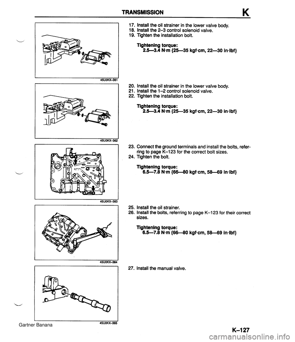
TRANSMISSION K 17. lnstall the oil strainer in the lower valve body. 18. lnstall the 2-3 control solenoid valve. 19. Tighten the installation bolt. Tightening torque: 2.5--3.4 N-m (2545 kgf-cm, 22--30 in4bf) 20. lnstall the oil strainer in the lower valve body. 21. lnstall the 1-2 control solenoid valve. 22. Tighten the installation bolt. Tightening torque: 2.54.4 N-m {25--35 kgf-cm, 22-30 inslbf) 23. Connect the ground terminals and install the bolts, refer- ring to page K-123 for the correct bolt sizes. 24. Tighten the bolt. Tightening torque: 6.5--7.8 N.m (66-80 kgf-cm, 58-69 in-lbf) 25. lnstall the oil strainer. 26. lnstall the bolts, referring to page K-123 for their correct sizes. Tightening torque: 6.5--7.8 N-m (66-80 kgf-cm, 58-69 in-lbf) 27. lnstall the manual valve. Gartner Banana
Page 530 of 1708

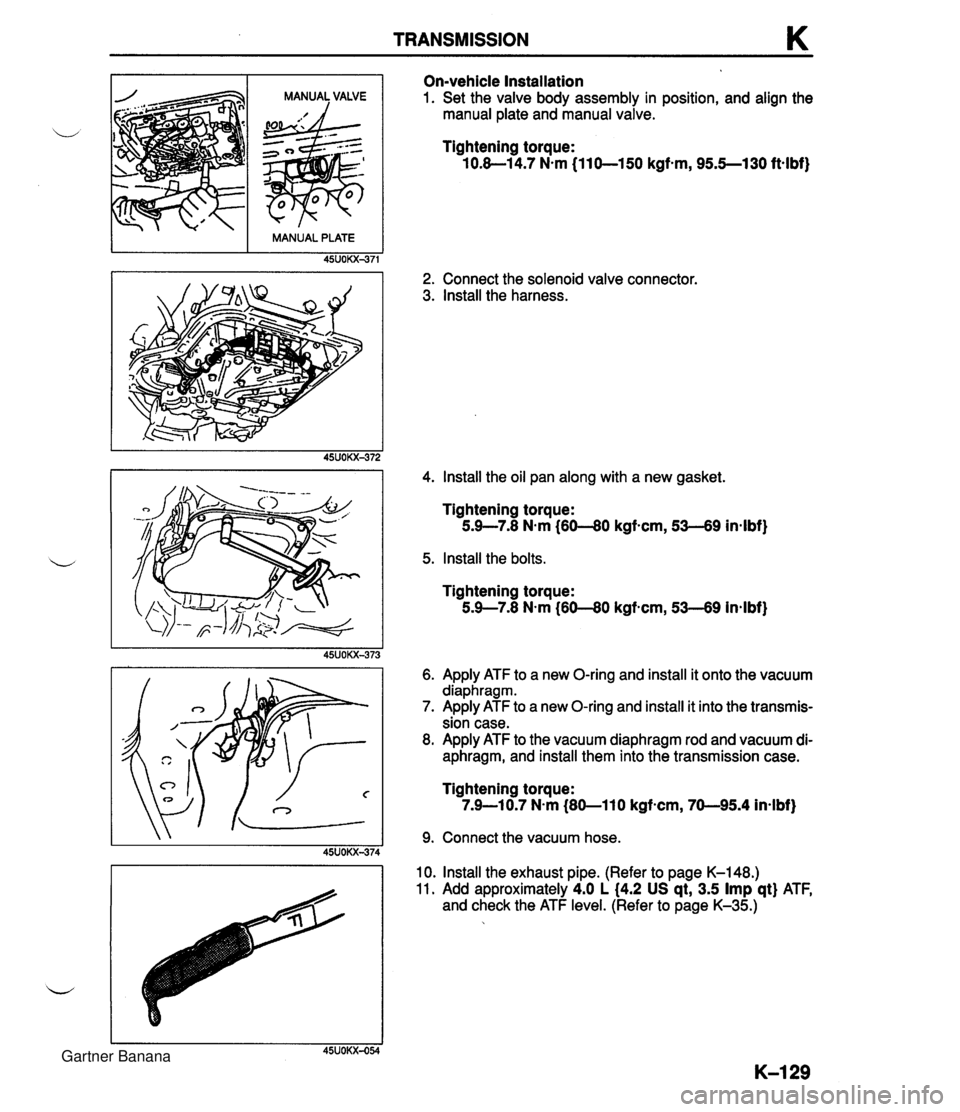
TRANSMISSION K On-vehicle Installation 1. Set the valve body assembly in position, and align the manual plate and manual valve. Tightening torque: 10.8-1 4.7 N.m (11 0-150 kgf-m, 95.5--130 ftalbf) 2. Connect the solenoid valve connector. 3. Install the harness. , . 4. Install the oil pan along with a new gasket. MANUAL PLATE Tightening torque: 5.9-7.8 N.m (60-80 kgf-cm, 53-69 in4bf) 45UOKX-371 5. Install the bolts. Tightening torque: 5.9-7.8 Nsm (60--80 kgf-cm, 53--69 inalbf) 6. Apply ATF to a new O-ring and install it onto the vacuum diaphragm. 7. Apply ATF to a new O-ring and install it into the transmis- sion case. 8. Apply ATF to the vacuum diaphragm rod and vacuum di- aphragm, and install them into the transmission case. Tightening torque: 7.9-1 0.7 N-m (80-1 10 kgf-cm, 70-95.4 in-lbf) 9. Connect the vacuum hose. 10. Install the exhaust pipe. (Refer to page K-148.) 11. Add approximately 4.0 L (4.2 US qt, 3.5 Imp qt) ATF, and check the ATF level. (Refer to page K-35.) Gartner Banana
Page 538 of 1708

TRANSMISSION K 7. Install a new snap ring onto the front of the output shaft. 8. Install the extension housing along with a new gasket. Tightening torque: 20-24 N-m (2.0-2.5 kgfem, 15--18 ft4bf) 9. Verify that the output shaft is locked with the manual le- ver in P range. 10. Set the rear clutch assembly on the top of the front clutch assembly. 11. Install the connecting shell and front planetary gear unit (rear clutch hub, front planetary pinion carrier, rear sun gear) onto the rear clutch assembly. 12. Install the front clutch, rear clutch, rear clutch hub, front planetary pinion carrier, connecting shell, internal gear, sun gear, bearing, and bearing races as a unit into the transmission case. 13. Set a new gasket into the front of the case. Gartner Banana
Page 545 of 1708

K TRANSMISSION 0 (3) Hold the stem and tighten the locknut. Tightening torque: 15--39 N-m (1.5-4.0 kgf-m, 11-28 ftelbf) Caution Applying compressed air to the servo piston for longer than 3 seconds at a time will damage the seal. I 1 37. Check the servo piston operation by applying com- 45UOM431 pressed air through the oil passage of the fourth gear band servo. Air pressure: 392 kPa (4.0 kg/cm2, 57 psi) max. MANUAL PLATE 38. Set a new gasket on the fourth gear band servo. Install the fourth gear band servo cover. Tightening torque: 5.0-6.8 N-m (50-70 kgfscm, 44--60 indbf) 39. Apply ATF to a new O-ring and install it onto the solenoid valve connector. 40. Install the solenoid valve connector in the transmission case. 41. Set the valve body assembly in piston, and align the manual plate and manual valve. 42. Install the bolts. Tightening torque: 10.8-14.7 N.m (110--150 kgf-cm, 95.5--130 in-lbf) Gartner Banana
Page 547 of 1708

K TRANSMISSION 52. Apply ATF to a new O-ring and install it onto the vehicle speed pulse generator. 53. Apply locking compound to the mounting bolt threads, then install the vehicle speed pulse generator. Tightening torque: 7.9-10.7 N-m (80-110 kgtcm, 70-95.4 inmlbf) 54. Apply ATF to the new O-rings and install them into the transmission case. 55. Install the lockup control solenoid. 56. Rotate the manual shaft fully rearward; then return it two notches to the N position. 57. Loosely tighten the parwneutral switch nuts. 58. Remove the screw on the switch body and move the parklneutral switch so that the screw hole on the switch body is aligned with the small hole inside the switch. - Check their alignment by inserting a 2.0mm (0.0079 in) diameter pin into the holes. 59. Tighten the switch attaching nuts. 60. Remove the pin, and tighten the screw into the hole. Tightening torque: 5.0--6.8 Nem (50-70 kgfecrn, 44-60 in-lbf) 61. Ensure that the torque converter is installed correctly by measuring the distance (A) between the end of the torque converter and the end of the converter housing. "A": 22.5mm (0.89 in) 62. Remove the transmission from the engine stand. Gartner Banana
Page 613 of 1708

M DIFFERENTIAL SLEEVE BLOCK BOLT (MI 4 x 1.5) dl Removal note Power plant frame (PPF) 1. Disconnect the wire harness from the PPF. 2. Support the transmission with a jack. 3. Remove the power plant frame bracket. (Manual trans- mission) 4. Remove the differential-side bolts, and pry out the spacer. 5. Remove the differential mounting spacer. 6. Turn a bolt (MI4 x 1.5) into the sleeve. 7. Twist and pull the bolt downward. 8. Install a bolt (M6 x 1) into the hole in the block to hold the sleeve, and remove the long bolt (MI4 x 1.5). 9. Remove the bolt ,(M6 x 1). Gartner Banana
Page 632 of 1708

MANUAL STEERING TROUBLESHOOTING GUIDE Problem Steering heavy Posslble Cause Poor lubrication, foreign material, or abnormal wear of steering ball joint Stuck or damaged lower arm ball joints lmproper steering pinion preload Damaged steering gear Malfunction of steering shaft joint lmproperly adjusted wheel alignment Malfunctioning steering gear Replace Replace gear Replace Replace Adjust Replace ~ction- Lubricate or replace section R N-12 N-12 N- 9 section R N-12 ~i&d~ection N-13 General instability while driving Steering wheel pulls to one side Shake (Steering wheel vibrates upidown) Worn or damaged stabilizer and/or suspension arm bushings Dragging brake Loose lower arm lmproperly adjusted wheel alignment lncorrect tire pressure Damaged or unbalanced wheel Worn or damaged steering joints lmproper steering pinion preload Weak front coil spring Worn or damaged stabilizer andlor suspension arm bushings Malfunctioning shock absorber lmproperly adjusted wheel alignment Excessive tire and/or wheel runout Loose lug nuts Unbalanced wheel(s) Incorrect tire pressure Incorrect tire pressure Unevenly worn tires Weak front spring Replace Repair Tighten Adjust Adjust Adjust or replace Replace Replace gear Replace Replace Replace Adjust Replace Tighten Adjust or replace section R section P section R section R section Q section Q N- 9 N-12 section R section R section R section R section Q section Q section Q Adjust Adjust Replace Replace section Q section Q section Q section R I Cracked or worn transmission mount I Cracked or worn engine mount 1 ~e~lace I section B lncorrect tire pressure Unevenly worn tires Malfunction of shock absorber Shimmy (Steering wheel vibrates circumferentially) Excessive steering wheel play Cracked or worn steering gear mount Loose steering gear mounting bolts Stuck or damaged steering ball joint Excessive tire and/or wheel runout Loose lug nuts Unbalanced wheel(s) Adjust Replace Replace Replace Replace Tighten Replace Replace Tighten Adjust or replace section Q section Q section R section J N-12 N-12 N-13 section Q section Q section Q I Loose shock absorber mounting bolts 1 Tighten I section R Stuck or damaged lower arm ball joint Cracked or worn suspension bushings Damaged or worn front wheel bearing lmproperly adjusted front wheel alignment Worn steering gear Worn or damaged steering joints Worn or damaged suspension arm bushings Loose steering gear mounting bolts I lmproperly adjusted front wheel alignment Poor steering wheel return Replace Replace Replace Adjust Replace Replace Replace Tighten Replace Adjust Replace Adjust Worn linkage &-tie-rod ball joint lncorrect tire pressure Stuck or damaged steering joints section R section R section M section R N-12 N- 9 section R N-12 N-12 section Q N- 9 section R Abnormal noise from steering system 25UONX-00! Improper steering pinion preload Ball joint not operating smoothly Steering shaft contacting something Loose steering gear Malfunctioning steering gear Obstruction near steering column Loose steering linkage Worn steering joints Replace gear Replace Repair Tighten Replace Repair or replace Tighten or replace Replace N-12 N-13 N- 9 N-12 N-12 N- 9 N-12 N- 9 Gartner Banana