coolant temperature MAZDA MX-5 1994 Owner's Manual
[x] Cancel search | Manufacturer: MAZDA, Model Year: 1994, Model line: MX-5, Model: MAZDA MX-5 1994Pages: 1708, PDF Size: 82.34 MB
Page 180 of 1708
![MAZDA MX-5 1994 Owners Manual TROUBLESHOOTING GUIDE lo 1 LOW IDLE SPEEDIROUGH IDLE - AFTER WARM-UP 3ESCRIPTION I Engine runs normally at idle during warm-up but vibrates excessively after warm-up ;TROUBLESHOOTING HINTS] I> Idle sp MAZDA MX-5 1994 Owners Manual TROUBLESHOOTING GUIDE lo 1 LOW IDLE SPEEDIROUGH IDLE - AFTER WARM-UP 3ESCRIPTION I Engine runs normally at idle during warm-up but vibrates excessively after warm-up ;TROUBLESHOOTING HINTS] I> Idle sp](/img/28/57072/w960_57072-179.png)
TROUBLESHOOTING GUIDE lo 1 LOW IDLE SPEEDIROUGH IDLE - AFTER WARM-UP 3ESCRIPTION I Engine runs normally at idle during warm-up but vibrates excessively after warm-up ;TROUBLESHOOTING HINTS] I> Idle speed control malfunction b AirlFuel mixture too lean Air leakage of intake air system Low fuel line pressure INSPECTION Check if "00" is displayed on Self-Diagnosis Check- er with ignition switch ON m? page F-79 Check switches for correct operation with Self- Diagnosis Checker Monitor Lamp and ignition switch ON page F-95 SELECT SW A Disconnect idle air control valve connector at idle and check if engine condition is charged IAC VALVE - Yes No - Yes - No Yes O Air/Fuel mixture too rich Fuel injection control malfunction (Correction for coolant temperature) @ Poor ignition spark Q Low engine compression ACTION Go to next step Diagnostic Trouble Code No. displayed Check for cause (Refer to specified check sequence) page F-81 "88" flashes Check PCME terminal 1 E voltage page F-145 Specification: Battery positive voltage (Ignition switch ON) 6 If OK, replace PCME page F-143 Q If not OK, check wiring between PCME and Self-Diagno- sis Checker page F-7 Go to next step Lamp not ONIOFF with specified switch Check for cause (Refer to specified check sequence) page F-96 Lamp always ON Check wiring between PCME terminal 1 D and Self-Diag- nosis Checker page F-7 Go to next step Check idle air control valve page F-106 Gartner Banana
Page 183 of 1708

TROUBLESHOOTING GUIDE INSPECTION >heck if throttle valve is closed throttle position Yes when accelerator released I 11 :heck if "00" is displayed on Self-Diagnosis Check- Yes w with ignition switch ON @? page F-79 HIGH IDLE SPEED - AFTER WARM-UP SELECT SW A SYSTEM SELECT 1 FROUBLESHOOTING HINTS] Excessive intake air supplied to engine O Throttle valve not fully closed @ ldle speed control malfunction Air valve not closing ldle air control valve stuck Incorrect coolant temperature signal STEP 1 >heck switches for correct operation with Self- I Yes liagnosis Checker Monitor Lamp and ignition ;witch ON page F-95 SELECT SW A ACTION Go to next step Check if throttle linkage is correctly installed and operates freely @? page F-103 o If OK, go to next step o If not OK, clean, adjust or replace linkage Daae 6103 Go to next step - Diagnostic Trouble Code No. displayed Check for cause (Refer to specified check sequence) @? page F-81 "88" flashes Check PCME terminal 1 E voltage @S page F-145 Specification: Battery positive voltage (Ignition switch ON) 6 If OK, replace PCME E=T page F-143 o If not OK, check wiring between PCME and Self-Diagno- sis Checker @? page F-7 Go to next step Lamp not ONlOFF with specified switch Check for cause (Refer to specified check sequence) E=T page F-96 am^ always ON Check wiring between PCME terminal ID and Self-Diag- IOS~S Checker @? page F-7 Gartner Banana
Page 230 of 1708
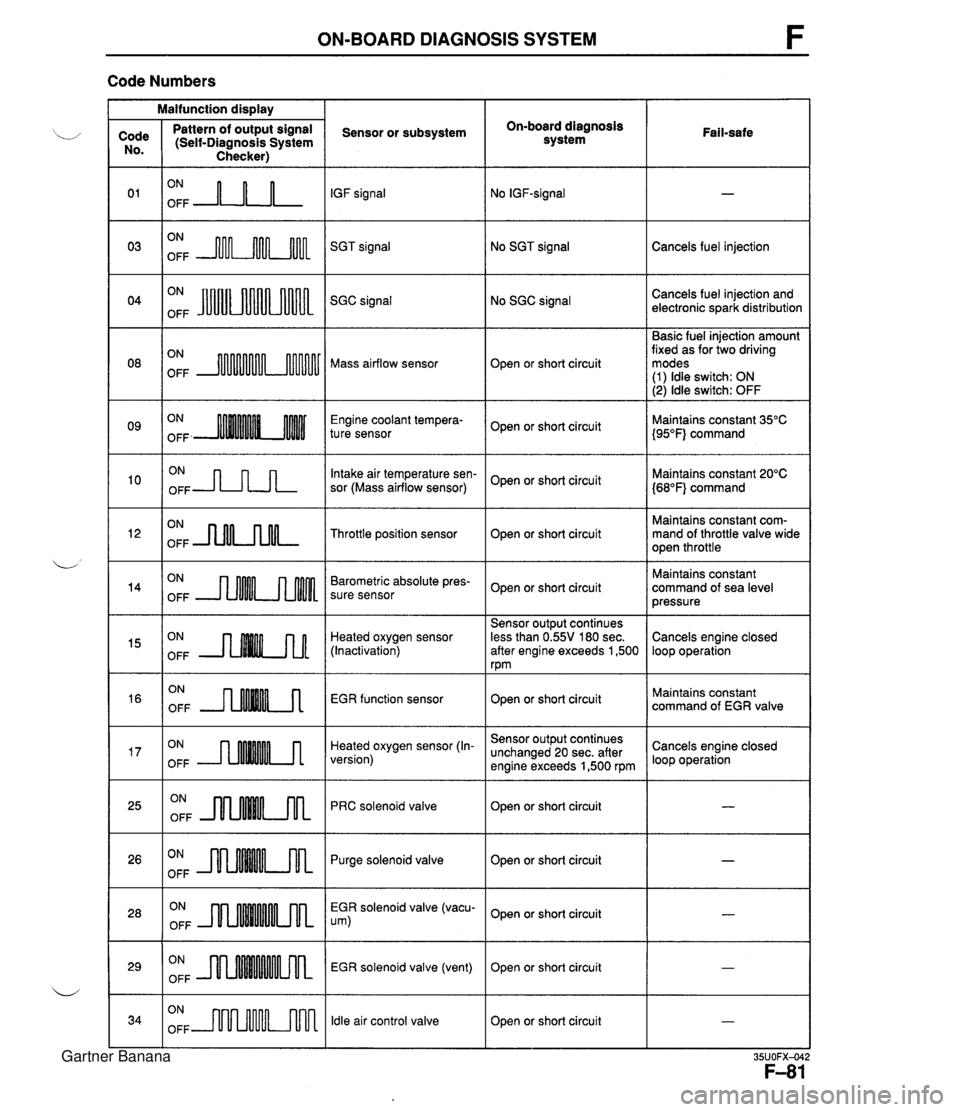
ON-BOARD DIAGNOSIS SYSTEM F Code Numbers Malfunction display On-board diagnosis system Code No. 0 1 03 Pattern of output signal (Self-Diagnosis System Checker) Sensor or subsystem IGF signal SGT signal Fail-safe ON OFF A-n-L ON OFF m No SGT signal ON OFF JuUu Cancels fuel injection No SGC signal Cancels fuel injection and electronic spark distribution SGC signal Basic fuel injection amount fixed as for two driving modes (1) ldle switch: ON (2) ldle switch: OFF ON OFF Mass airflow sensor Open or short circuit Engine coolant tempera- ture sensor ON OFF -JLnn Open or short circuit Intake air temperature sen- sor (Mass airflow sensor) Maintains constant 35°C {95"F} command Maintains constant 20°C {68"F} command Open or short circuit ON OFF -nNLnM- Maintains constant com- mand of throttle valve wide open throttle Throttle position sensor Open or short circuit ON OFF Barometric absolute pres- sure sensor Maintains constant command of sea level pressure Open or short circuit Heated oxygen sensor (Inactivation) EGR function sensor Sensor output continues less than 0.55V 180 sec. after engine exceeds 1,500 rpm Cancels engine closed loop operation ON OFF ON OFF --nMM.A ON OFF --rMMMA Open or short circuit Heated oxygen sensor (In- version) Maintains constant command of EGR valve ON OFF JlnMkm Sensor output continues unchanged 20 sec. after engine exceeds 1,500 rpm PRC solenoid valve Cancels engine closed loop operation Open or short circuit Open or short circuit I - ON OFF m Purge solenoid valve ON OFF EGR solenoid valve (vacu- um) ON OFF Open or short circuit EGR solenoid valve (vent) ldle air control valve - Open or short circuit ON OFF m Open or short circuit I - Gartner Banana
Page 235 of 1708
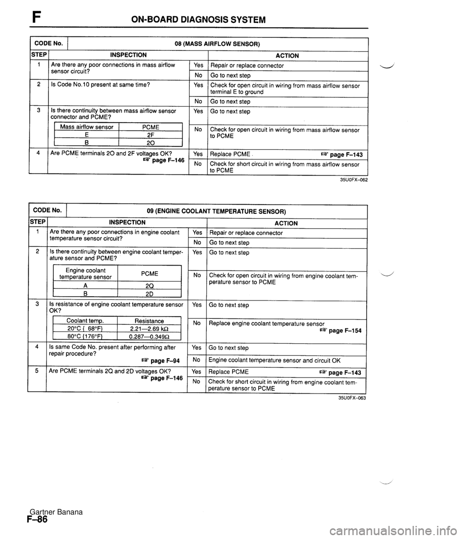
F ON-BOARD DIAGNOSIS SYSTEM CODE No. ACTION Yes I Repair or replace connector 08 (MASS AIRFLOW SENSOR) iTEP 1 No I Go to next step INSPECTION Are there any poor connections in mass airflow sensor circuit? Yes 2 Check for open circuit in wiring from mass airflow sensor terminal E to wound Is Code No.10 present at same time? No ( Go to next step 1 Is there continuity between mass airflow sensor connector and PCME? Yes Go to next step Mass airflow sensor E B I Yes I Replace PCME . us page F-143 PCME 2F 20 No Check for short circuit in wiring from mass airflow sensor to PCME Are PCME terminals 20 and 2F voltages OK? page F-146 Check for open circuit in wiring from mass airflow sensor to PCME CODE No. ACTION 09 (ENGINE COOLANT TEMPERATURE SENSOR) STEP 1 Repair or replace connector Go to next step INSPECTION Are there any poor connections in engine coolant temperature sensor circuit? Go to next step Yes - No 2 Engine coolant temperature sensor PCME Check for open circuit in wiring from engine coolant tem- perature sensor to PCME Is there continuity between engine coolant temper- ature sensor and PCME? 4 Is resistance of engine coolant temperature sensor 1 /om I yes Yes Go to next step Coolant temp. Resistance 1 I 20°C ( 68°F) 1 2.21-2.69 kR Replace engine coolant temperature sensor page F-154 Is same Code No. present after performing after repair procedure? page F-94 Go to next step Engine coolant temperature sensor and circuit OK Are PCME terminals 2Q and 2D voltages OK? page F-146 Re~lace PCME ~aae F-143 Check for short circuit in wiring from engine coolant tem- perature sensor to PCME Gartner Banana
Page 237 of 1708
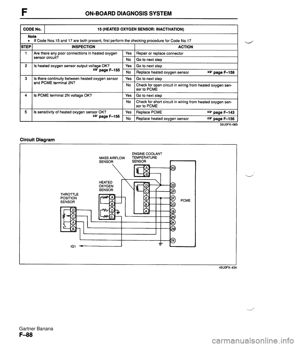
F ON-BOARD DIAGNOSIS SYSTEM CODE No. 15 (HEATED OXYGEN SENSOR: INACTIVATION) 111 Are there any poor connections in heated oxygen sensor circuit? Note a If Code Nos.15 and 17 are both present, first perform the checking procedure for Code No.17 STEP 1 INSPECTION I ACTION 2 3 Circuit Diagram I Yes No 4 5 ENGINE COOLANT MASS AIRFLOW TEMPERATURE SENSOR SENSOR ~ Repair or replace connector Go to next steD Is heated oxygen sensor output voltage OK? page F-155 Is there continuity between heated oxygen sensor and PCME terminal 2N? THROTTLE POSITION SENSOR 35UOFX-065 Is PCME terminal 2N voltage OK? Is sensitivity of heated oxygen sensor OK? * page F-156 PCME Yes No Yes No Go to next step Replace heated oxygen sensor r@ page F-156 Go to next step Check for open circuit in wiring from heated oxygen sen- sor to PCME Yes No Yes No Go to next step Check for short circuit in wiring from heated oxygen sen- sor to PCME Replace PCME aPi. page F-143 Replace heated oxygen sensor r@ page F-156 Gartner Banana
Page 254 of 1708
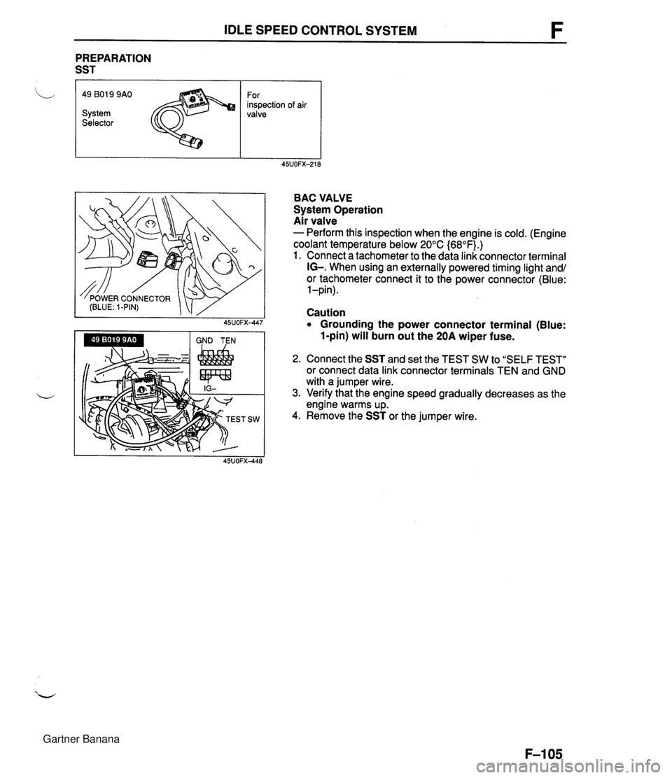
IDLE SPEED CONTROL SYSTEM PREPARATION SST I 'L 49 801 9 9AO For inspection of air System valve Selector BAC VALVE System Operation Air valve - Perform this inspection when the engine is cold. (Engine coolant temperature below 20°C {68OF).) 1. Connect a tachometer to the data link connector terminal IG-. When using an externally powered timing light and/ or tachometer connect it to the power connector (Blue: 1 -pin). Caution Grounding the power connector terminal (Blue: 1-pin) will burn out the 20A wiper fuse. 2. Connect the SST and set the TEST SW to "SELF TEST" or connect data link connector terminals TEN and GND with a jumper wire. 3. Verify that the engine speed gradually decreases as the engine warms up. 4. Remove the SST or the jumper wire. Gartner Banana
Page 271 of 1708

PRESSURE REGULATOR CONTROL SYSTEM PRESSURE REGULATOR CONTROL SYSTEM DATA LINK CONNECTOR - CLUTCH SWITCH (MT) (TEN TERMINAL) PARKINEUTRAL SWITCH (PCMT) (AT) THROTTLE POSITION SENSOR L 1 ,,,, INTAKE AIR TEMPERATURE 1 SENSOR (IN MASS AIRFLOW SENSOR) -;- ENGINE COOLANT TEMPERATURE SENSOR PRC SOLENOID VALVE CRANKSHAFT POSITION SENSOR PRESSURE REGULATOR PCME I Above 90°C {194OF} ( Above 70°C {158'F} I Throttle valve closed throttle position or no load condition I Approx. 150 1 I Operating condition Coolant temperature I Intake air temperature I Engine condition I I To prevent percolation of the fuel during hot restart idle, vacuum to the pressure regulator is momentarily cut, and the fuel injection pressure is increased to slightly more than 284 kPa (2.9 kgf/cm2, 41.2 psi}. Operating time (sec) Gartner Banana
Page 273 of 1708

F EXHAUST GAS RECIRCULATION (EGR) EXHAUST GAS RECIRCULATION (EGR) PREPARATION SST I 49 9200 162 Engine Signal Monitor 49 GO1 8 904 Sheet DESCRIPTION For inspection of EGR For inspection of EGR 49 GO1 8 903 For inspection of Adapter EGR harness / TO AIR CLEANER HOUSING I THROTTLE POSITION ENGINE COOLANT SENSOR SENSOR TEMPERATURE CRANKSHAFT SENSOR POSITION SENSOR EGR SOLENOID VALVE (VACUUM) EGR SOLENOID VALVE (VENT) / PCME I This ~~st~rn~recirculates a small amount of exhaust gas into the intake manifold to reduce the combus- tion temperature, and reduce the NOx emissions. This system consists of the EGR control valve, EGR function sensor, two solenoid valves, powertrain control module (engine) (PCME) and input devices. Gartner Banana
Page 274 of 1708
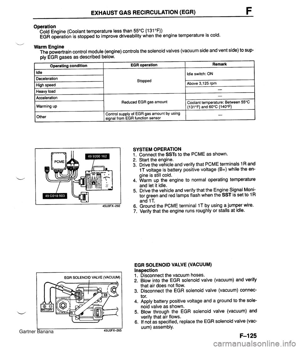
EXHAUST GAS RECIRCULATION (EGR) Operation Cold Engine (Coolant temperature less than 55°C (1 31 OF)) EGR operation is stopped to improve driveability when the engine temperature is cold. u Warm Engine The powertrain control module (engine) controls the solenoid valves (vacuum side and vent side) to sup- ply EGR gases as described below. Remark Operating condition Idle Deceleration High speed Heavy load EGR SOLENOID VALVE (VACUUM) I I EGR operation Acceleration Warming up Other SYSTEM OPERATION 1. Connect the SSTs to the PCME as shown. 2. Start the engine. 3. Drive the vehicle and verify that PCME terminals 1 R and 1 T voltage is battery positive voltage (B+) while the en- gine is still cold. 4. Warm up the engine to normal operating temperature and let it idle. 5. Drive the vehicle and verify that the Engine Signal Moni- tor green and red lamps flash when the SST is set to 1 R and 1 T. 6. Ground the PCME terminal IT by using a jumper wire. 7. Verify that the engine runs roughly or stalls at idle. Stopped EGR SOLENOID VALVE (VACUUM) Inspection 1. Disconnect the vacuum hoses. 2. Blow into the EGR solenoid valve (vacuum) and verify that air does not flow. 3. Disconnect the EGR solenoid valve (vacuum) connec- tor. 4. Apply battery positive voltage and a ground to the sole- noid valve as shown. 5. Blow through the EGR solenoid valve (vacuum) and verify that air flows. 6. If not as specified, replace the EGR solenoid valve (vac- uum) assembly. Idle switch: ON Above 3,125 rpm - Reduced EGR gas amount Control supply of EGR gas amount by using signal from EGR function sensor - Coolant temperature: Between 55OC (1 31 OF) and 60°C {140°F) - Gartner Banana
Page 280 of 1708

FUEL EVAPORATIVE SYSTEM FUEL EVAPORATIVE SYSTEM DESCRIPTION The fuel evaporative system consists of the fuel vapor valve, the two-way check valve, the charcoal can- ister, the purge solenoid valve, the powertrain control module (engine), and the input devices. The amount of evaporative fumes introduced into the engine and burned is controlled by the solenoid valve in relation to the engine's operating conditions. To maintain the best engine performance, the solenoid valve is controlled by the powertrab control module (engine). THROTTLE 1-1 POSITION SENSOR I1 I I (IDLE SWITCH) 7 BAROMETIC ABSOLUTE PRESSURE SENSOR PARWNEUTRAL SWITCH (AT) MASS AIRFLOW SENSOR CRANKSHAFT POSITION SENSOR (SGT-SIGNAL) n - DUTY - LOW HIGH (ENGINE) CHARCOAL PURGE SOLENOID VALVE CANISTER HEATED OXYGEN SENSOR ENGINE COOLANT POWERTRAIN TEMPERATURE SENSOR CONTROL MODULE CHECK VALVE # 11 FUEL VAPOR VALVE Operation The purge solenoid valve is controlled by duty signals from the powertrain control module (engine) to per- form purging of the charcoal canister. Purging is done when these conditions are met: i/ 1. After warm-up. 2. Driving in gear. 3. Accelerator pedal depressed (idle switch OFF). 4. Heated oxygen sensor functioning normally. Gartner Banana