washer fluid MAZDA MX-5 1994 Workshop Manual
[x] Cancel search | Manufacturer: MAZDA, Model Year: 1994, Model line: MX-5, Model: MAZDA MX-5 1994Pages: 1708, PDF Size: 82.34 MB
Page 7 of 1708

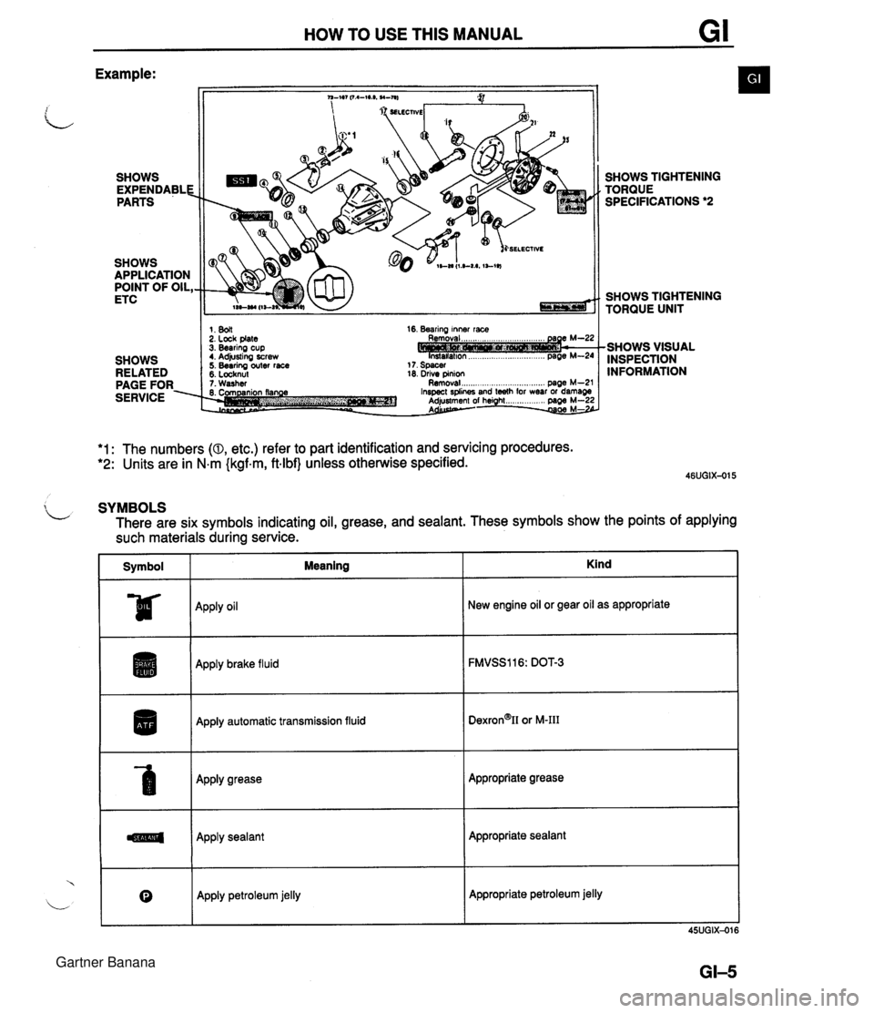
HOW TO USE THIS MANUAL Example: SHOWS EXPENDABLE PARTS SHOWS APPLICATION POINT OF OIL, ETC SHOWS RELATED PAGE FOR. SERVICE SELECTIVE 1. 8011 2. Lock plate 3. Bearing cup t. Adjusting screw 5. Bearing outer race 5. Locknul 16. Bearing inner race 18. drive pinion 1. Washer Removal ..................... .. .... page M-2' SHOWS TIGHTENING TORQUE SPECIFICATIONS *2 SHOWS TIGHTENING TORQUE UNIT -SHOWS VISUAL INSPECTION INFORMATION *1: The numbers (0, etc.) refer to part identification and servicing procedures. *2: Units are in N.m {kgf.m, ftlbf} unless otherwise specified. $ L SYMBOLS There are six symbols indicating oil, grease, and sealant. These symbols show the points of applying such materials during service. Symbol I Meaning ~pp~y oil Apply brake fluid I Apply automatic transmission fluid Apply grease Apply sealant Kind 0 New engine oil or gear oil as appropriate Apply petroleum jelly Appropriate grease Appropriate sealant Appropriate petroleum jelly Gartner Banana
Page 23 of 1708

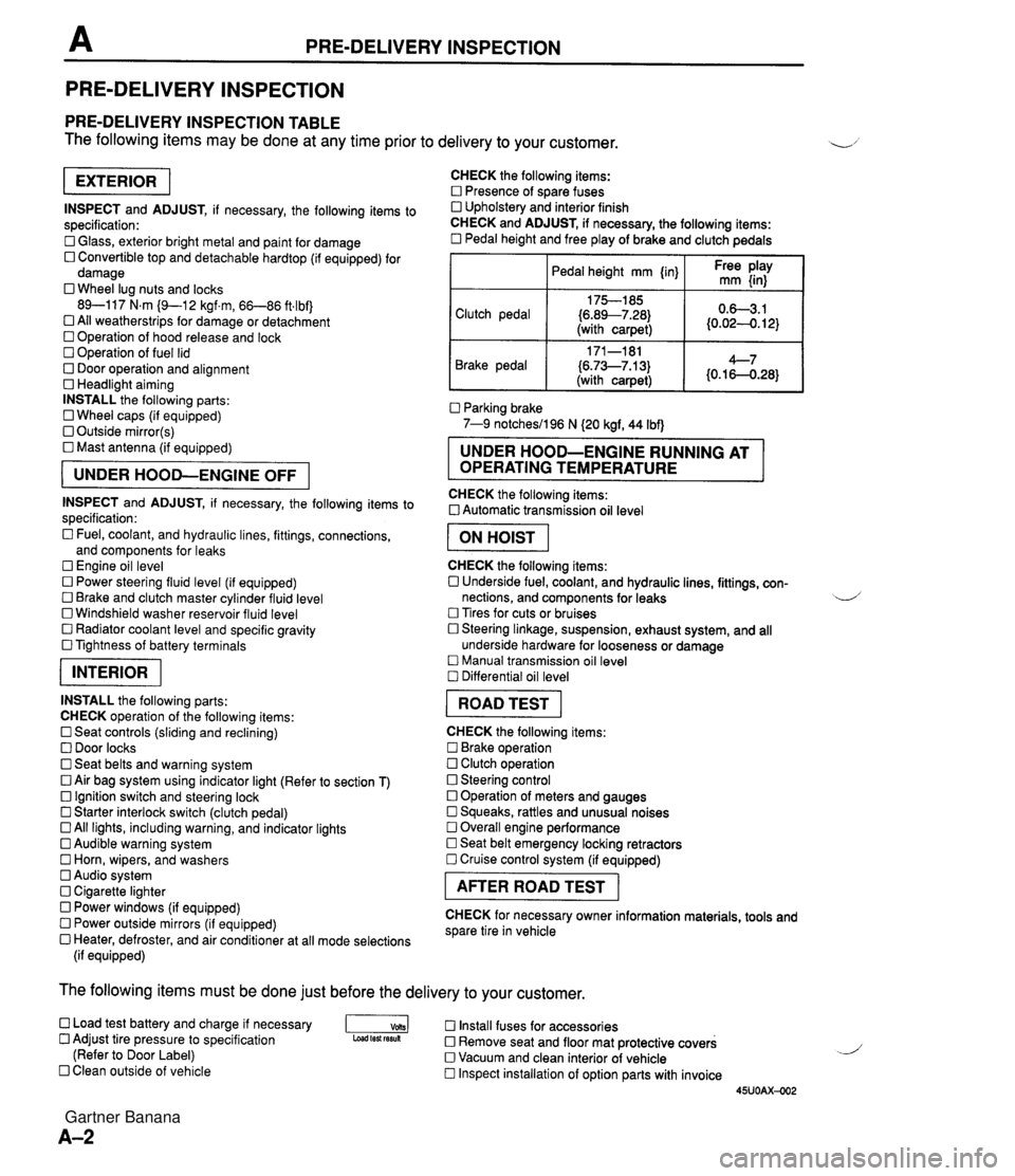
PRE-DELIVERY INSPECTION PRE-DELIVERY INSPECTION PRE-DELIVERY INSPECTION TABLE The following items may be done at any time prior to delivery to your customer. INSPECT and ADJUST, if necessary, the following items to specification: 0 Glass, exterior bright metal and paint for damage 0 Convertible top and detachable hardtop (if equipped) for damage 0 Wheel lug nuts and locks 89-117 N.m (9-1 2 kgf.m, 66-86 ft4bf) 0 All weatherstrips for damage or detachment Operation of hood release and lock Operation of fuel lid 0 Door operation and alignment Headlight aiming INSTALL the following parts: Wheel caps (if equipped) 0 Outside mirror(s) 0 Mast antenna (if equipped) UNDER HOOD-ENGINE OFF INSPECT and ADJUST, if necessary, the following items to specification : Fuel, coolant, and hydraulic lines, fittings, connections, and components for leaks Engine oil level 0 Power steering fluid level (if equipped) Brake and clutch master cylinder fluid level 0 Windshield washer reservoir fluid level 0 Radiator coolant level and specific gravity 0 Tightness of battery terminals pKiq INSTALL the following parts: CHECK operation of the following items: 0 Seat controls (sliding and reclining) 0 Door locks 0 Seat belts and warning system 0 Air bag system using indicator light (Refer to section T) Ignition switch and steering lock 0 Starter interlock switch (clutch pedal) All lights, including warning, and indicator lights 0 Audible warning system 0 Horn, wipers, and washers Audio system 0 Cigarette lighter Power windows (if equipped) 0 Power outside mirrors (if equipped) 0 Heater, defroster, and air conditioner at all mode selections (if equipped) CHECK the following items: Presence of spare fuses 0 Upholstery and interior finish CHECK and ADJUST, if necessary, the following items: 0 Pedal height and free play of brake and clutch pedals I Pedal height mm {in} I Ft: $iy I Clutch pedal {6.89--7.28) (with carpet) Parking brake 7-9 notchesil96 N (20 kgf, 44 Ibf) 0.63.1 (0.024. 12) Brake pedal RUNNING AT OPERATING TEMPERATURE CHECK the following items: 0 Automatic transmission oil level 171-181 (6.73--7.13) (with carpet) I ON HOIST I 4--7 {0.16-0.28} CHECK the following items: 0 Underside fuel, coolant, and hydraulic lines, fittings, con- nections, and components for leaks 4 Tires for cuts or bruises 0 Steering linkage, suspension, exhaust system, and all underside hardware for looseness or damage Manual transmission oil level Differential oil level I ROAD TEST I CHECK the following items: Brake operation Clutch operation 0 Steering control 0 Operation of meters and gauges Squeaks, rattles and unusual noises 0 Overall engine performance Seat belt emergency locking retractors 0 Cruise control system (if equipped) I AFTER ROAD TEST I CHECK for necessary owner information materials, tools and spare tire in vehicle The following items must be done just before the delivery to your customer. 0 Load test battery and charge if necessary -1 Install fuses for accessories Adjust tire pressure to specification Load test fesuk 0 Remove seat and floor mat protective covers (Refer to Door Label) 0 Vacuum and clean interior of vehicle Clean outside of vehicle Inspect installation of option parts with invoice 45UOAX-002 Gartner Banana
Page 676 of 1708

BRAKE SYSTEM P MASTER CYLINDER (STANDARD) Removal / Installation 1 lnspection 1. Remove in the order shown in the figure, referring to Removal Note. ,, 2. Install in the reverse order of removal, referring to Installation Note. 3. After installation, add brake fluid, bleed the brakes, and check for fluid leakaae. 1. Fluid level sensor connector 5. Proportioning bypass valve and bracket Inspection ................... page P-13 6. Master cylinder 2. Brake pipe Installation Note ............. page P-12 Removal Note ............... page P-12 Disassembly 1 Assembly I 3. Connector bolt Inspection ................. page P-18 4. Nut and washer Gartner Banana
Page 679 of 1708

BRAKE SYSTEM MASTER CYLINDER (ABS) Removal / Installation / lnspection 1. Remove in the order shown in the figure, referring to Removal Note. 2. Install in the reverse order of removal, referring to Installation Note. 3. After installation, add brake fluid, bleed air, and check for fluid leakage. Caution Brake fluid will damage painted surfaces. If it does get on a painted surface, wipe it off immedi- Fluid level sensor connector 5. Proportioning bypass valve and bracket Inspection ................... page P-17 6. Master cylinder Brake pipe Installation Note ............. page P-15 Removal Note ............... page P-15 Disassembly 1 Assembly 1 Connector bolt Inspection ................. page P-18 Nut and washer Gartner Banana
Page 884 of 1708

WARNING LIGHT AND SENDER UNIT T OHMMETER Washer Level Indicator lnspection 1. Disconnect the connector from the washer level sensor. 2. Jump terminal-wire L (harness side) to a body ground. 3. Start the engine and check that the WASHER indicator illuminates. 4. If there is no illumination, check the bulb, wiring harness, and sensor. Replace or repair as necessary. Washer Level Sensor lnspection 1. Connect the sensor connector (sensor side) to an ohm- meter. 2. Move the sensor float up and down. 3. Verify that there is continuity when the float is at the low- est point. BRAKE FLUID LEVEL SENSOR lnspection 1. Check for continuity of the sensor. 2. If continuity is not as specified, replace the level sensor. Float level Below MIN Above MIN BUCKLE SWITCt Continuity Yes No OHMMETER -1 PARKING BRAKE SWITCH lnspection 1. Disconnect the parking brake switch connector. 2. Check for continuity between the switch connector and ground. I Lever I Continuity I 3. If continuity is not as specified, adjust or replace the parking brake switch. (Refer to section P.) Pulled one notch Released BUCKLE SWITCH lnspection 1. Disconnect the buckle switch connector 2. Check for continuity of the switch. Yes No Seat belt I Continuity Seat belt buckled Seat belt unbuckled No Yes 3. If continuity is not as specified, replace the buckle switch. Gartner Banana