coolant MAZDA MX-5 1994 Repair Manual
[x] Cancel search | Manufacturer: MAZDA, Model Year: 1994, Model line: MX-5, Model: MAZDA MX-5 1994Pages: 1708, PDF Size: 82.34 MB
Page 199 of 1708
![MAZDA MX-5 1994 Repair Manual TROUBLESHOOTING GUIDE DESCRIPTION I : Engine unexpectedly stops running at idle when AIC, PIS, or EIL ON AX, PIS, headlight, blower fan and electric coolant fan OK 20 [TROUBLESHOOTING HINTS] O ldle sp MAZDA MX-5 1994 Repair Manual TROUBLESHOOTING GUIDE DESCRIPTION I : Engine unexpectedly stops running at idle when AIC, PIS, or EIL ON AX, PIS, headlight, blower fan and electric coolant fan OK 20 [TROUBLESHOOTING HINTS] O ldle sp](/img/28/57072/w960_57072-198.png)
TROUBLESHOOTING GUIDE DESCRIPTION I : Engine unexpectedly stops running at idle when AIC, PIS, or EIL ON AX, PIS, headlight, blower fan and electric coolant fan OK 20 [TROUBLESHOOTING HINTS] O ldle speed control malfunction No input signal from switch ldle speed misadjustment ldle air control valve stuck ENGINE STALLS AT IDLE - WHEN AIC, PIS, OR EIL ON INSPECTION Check if "00" is displayed on Self-Diagnosis Check- er with ignition switch ON * page F-79 SELECT SW A SYSTEM SELECT 1 Check switches for correct operation with Self- Diagnosis Checker Monitor Lamp and ignition switch ON tw page F-95 SELECT SW A Check if PCME terminal voltages are OK (IG, 1 P, 1 U, 2D,2Q and 2W) page F-146 Check for correct idle speed page F-77 ldle speed: 850 2 50 rpm (MT) 800 2 50 rpm (AT) GND TEN 1 AIR ADJUSTING SCREW CONNECT TERMINAL - Yes - No Yes - No Yes - No Yes - No Go to next step ACTION Diagnostic Trouble Code No. displayed Check for cause (Refer to specified check sequence) page F-81 "88" flashes Check PCME terminal 1 E voltage page F-145 Specification: Battery positive voltage (Ignition switch ON) 0 If OK, replace PCME page F-143 s If not OK, check wiring between PCME and Self-Diagno- sis Checker page F-7 Go to next step Lamp not ONlOFF with specified switch Check for cause (Refer to specified check sequence) page F-96 Lamp always ON Check wiring between PCME terminal 1 D and Self-Diag- nosis Checker IS page F-7 Go to next step Check for cause (Refer to "Check Point for Each Termi- nal") page F-148 Go to next step Adjust page F-77 Gartner Banana
Page 224 of 1708
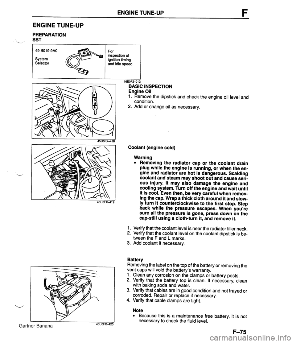
ENGINE TUNE-UP ENGINE TUNE-UP PREPARATION L" SST r I I 16EOF2-012 BASIC INSPECTION Engine Oil 1. Remove the dipstick and check the engine oil level and condition. 2. Add or change oil as necessary. 49 B019 9AO System Selector Coolant (engine cold) For inspection of ignition timing and idle speed Warning Removing the radiator cap or the coolant drain plug while the engine is running, or when the en- gine and radiator are hot is dangerous. Scalding coolant and steam may shoot out and cause seri- ous injury. It may also damage the engine and cooling system. Turn off the engine and wait until it is cool. Even then, be very careful when remov- ing the cap. Wrap a thick cloth around it and slow- ly turn it counterclockwise to the first stop. Step back while the pressure escapes. When you're sure all the pressure is gone, press down on the cap-still using a cloth-turn it, and remove it. 1. Verify that the coolant level is near the radiator filler neck. 2. Verify that the coolant level on the coolant dipstick is be- tween the F and L marks. 3. Add coolant if necessary. Battery Removing the label on the top of the battery or removing the vent caps will void the battery's warranty. 1. Clean any corrosion on the clamps or battery posts. 2. Verify that the battery top is clean. If necessary, clean with baking soda and water. 3. Verify that cables are in good condition and not frayed or corroded. Repair or replace if necessary. 4. Verify that cable clamps are tight. Note Because this is a maintenance free battery, it is not necessary to check the fluid level. Gartner Banana
Page 226 of 1708
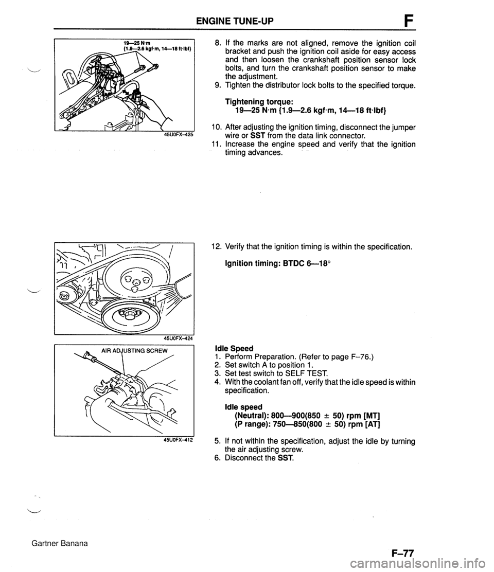
ENGINE TUNE-UP 8. If the marks are not aligned, remove the ignition coil bracket and push the ignition coil aside for easy access and then loosen the crankshaft position sensor lock bolts, and turn the crankshaft position sensor to make the adjustment. 9. Tighten the distributor lock bolts to the specified torque. Tightening torque: 19-25 N-m (1.9-2.6 kgfem, 14--18 ftqlbf) 10. After adjusting the ignition timing, disconnect the jumper wire or SST from the data link connector. 11. Increase the engine speed and verify that the ignition timing advances. 12. Verify that the ignition timing is within the specification. Ignition timing: BTDC 6-18' ldle Speed 1. Perform Preparation. (Refer to page F-76.) 2. Set switch A to position 1. 3. Set test switch to SELF TEST. 4. With the coolant fan off, verify that the idle speed is within specification. ldle speed (Neutral): 800-900(850 + 50) rpm [MT] (P range): 750--850(800 -c 50) rpm [AT] 5. If not within the specification, adjust the idle by turning the air adjusting screw. 6. Disconnect the SST. Gartner Banana
Page 230 of 1708
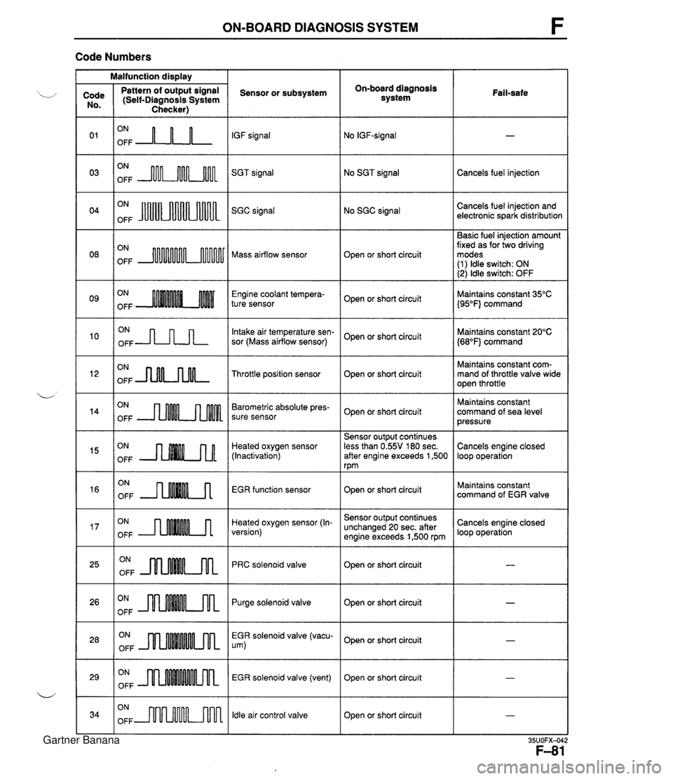
ON-BOARD DIAGNOSIS SYSTEM F Code Numbers Malfunction display On-board diagnosis system Code No. 0 1 03 Pattern of output signal (Self-Diagnosis System Checker) Sensor or subsystem IGF signal SGT signal Fail-safe ON OFF A-n-L ON OFF m No SGT signal ON OFF JuUu Cancels fuel injection No SGC signal Cancels fuel injection and electronic spark distribution SGC signal Basic fuel injection amount fixed as for two driving modes (1) ldle switch: ON (2) ldle switch: OFF ON OFF Mass airflow sensor Open or short circuit Engine coolant tempera- ture sensor ON OFF -JLnn Open or short circuit Intake air temperature sen- sor (Mass airflow sensor) Maintains constant 35°C {95"F} command Maintains constant 20°C {68"F} command Open or short circuit ON OFF -nNLnM- Maintains constant com- mand of throttle valve wide open throttle Throttle position sensor Open or short circuit ON OFF Barometric absolute pres- sure sensor Maintains constant command of sea level pressure Open or short circuit Heated oxygen sensor (Inactivation) EGR function sensor Sensor output continues less than 0.55V 180 sec. after engine exceeds 1,500 rpm Cancels engine closed loop operation ON OFF ON OFF --nMM.A ON OFF --rMMMA Open or short circuit Heated oxygen sensor (In- version) Maintains constant command of EGR valve ON OFF JlnMkm Sensor output continues unchanged 20 sec. after engine exceeds 1,500 rpm PRC solenoid valve Cancels engine closed loop operation Open or short circuit Open or short circuit I - ON OFF m Purge solenoid valve ON OFF EGR solenoid valve (vacu- um) ON OFF Open or short circuit EGR solenoid valve (vent) ldle air control valve - Open or short circuit ON OFF m Open or short circuit I - Gartner Banana
Page 235 of 1708
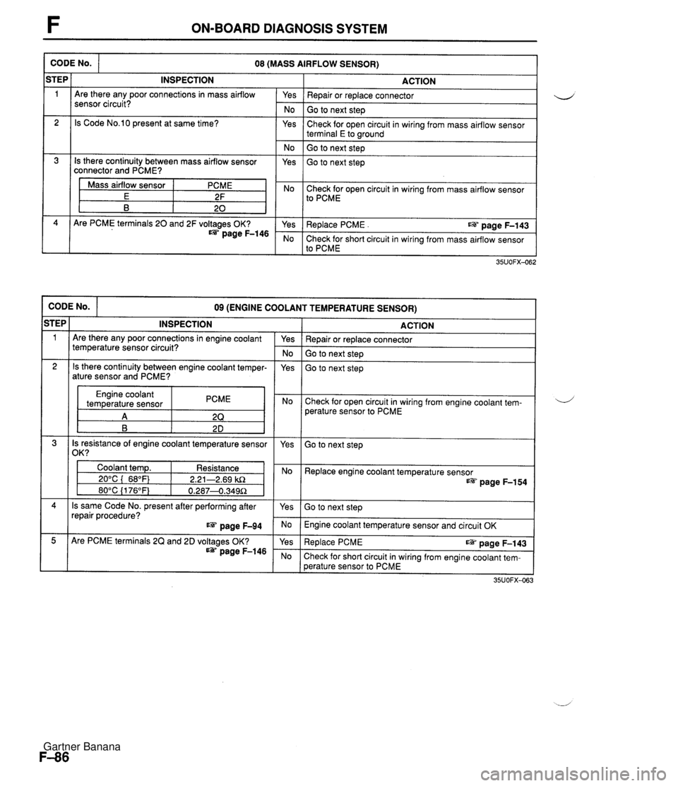
F ON-BOARD DIAGNOSIS SYSTEM CODE No. ACTION Yes I Repair or replace connector 08 (MASS AIRFLOW SENSOR) iTEP 1 No I Go to next step INSPECTION Are there any poor connections in mass airflow sensor circuit? Yes 2 Check for open circuit in wiring from mass airflow sensor terminal E to wound Is Code No.10 present at same time? No ( Go to next step 1 Is there continuity between mass airflow sensor connector and PCME? Yes Go to next step Mass airflow sensor E B I Yes I Replace PCME . us page F-143 PCME 2F 20 No Check for short circuit in wiring from mass airflow sensor to PCME Are PCME terminals 20 and 2F voltages OK? page F-146 Check for open circuit in wiring from mass airflow sensor to PCME CODE No. ACTION 09 (ENGINE COOLANT TEMPERATURE SENSOR) STEP 1 Repair or replace connector Go to next step INSPECTION Are there any poor connections in engine coolant temperature sensor circuit? Go to next step Yes - No 2 Engine coolant temperature sensor PCME Check for open circuit in wiring from engine coolant tem- perature sensor to PCME Is there continuity between engine coolant temper- ature sensor and PCME? 4 Is resistance of engine coolant temperature sensor 1 /om I yes Yes Go to next step Coolant temp. Resistance 1 I 20°C ( 68°F) 1 2.21-2.69 kR Replace engine coolant temperature sensor page F-154 Is same Code No. present after performing after repair procedure? page F-94 Go to next step Engine coolant temperature sensor and circuit OK Are PCME terminals 2Q and 2D voltages OK? page F-146 Re~lace PCME ~aae F-143 Check for short circuit in wiring from engine coolant tem- perature sensor to PCME Gartner Banana
Page 237 of 1708
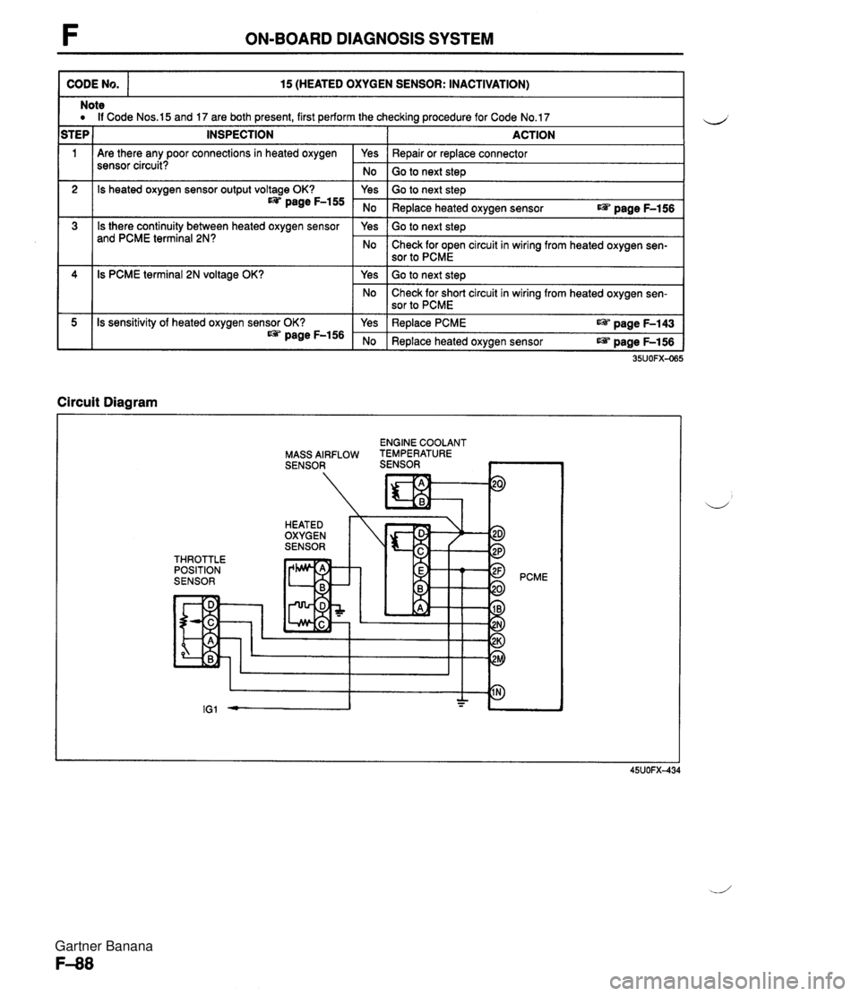
F ON-BOARD DIAGNOSIS SYSTEM CODE No. 15 (HEATED OXYGEN SENSOR: INACTIVATION) 111 Are there any poor connections in heated oxygen sensor circuit? Note a If Code Nos.15 and 17 are both present, first perform the checking procedure for Code No.17 STEP 1 INSPECTION I ACTION 2 3 Circuit Diagram I Yes No 4 5 ENGINE COOLANT MASS AIRFLOW TEMPERATURE SENSOR SENSOR ~ Repair or replace connector Go to next steD Is heated oxygen sensor output voltage OK? page F-155 Is there continuity between heated oxygen sensor and PCME terminal 2N? THROTTLE POSITION SENSOR 35UOFX-065 Is PCME terminal 2N voltage OK? Is sensitivity of heated oxygen sensor OK? * page F-156 PCME Yes No Yes No Go to next step Replace heated oxygen sensor r@ page F-156 Go to next step Check for open circuit in wiring from heated oxygen sen- sor to PCME Yes No Yes No Go to next step Check for short circuit in wiring from heated oxygen sen- sor to PCME Replace PCME aPi. page F-143 Replace heated oxygen sensor r@ page F-156 Gartner Banana
Page 247 of 1708
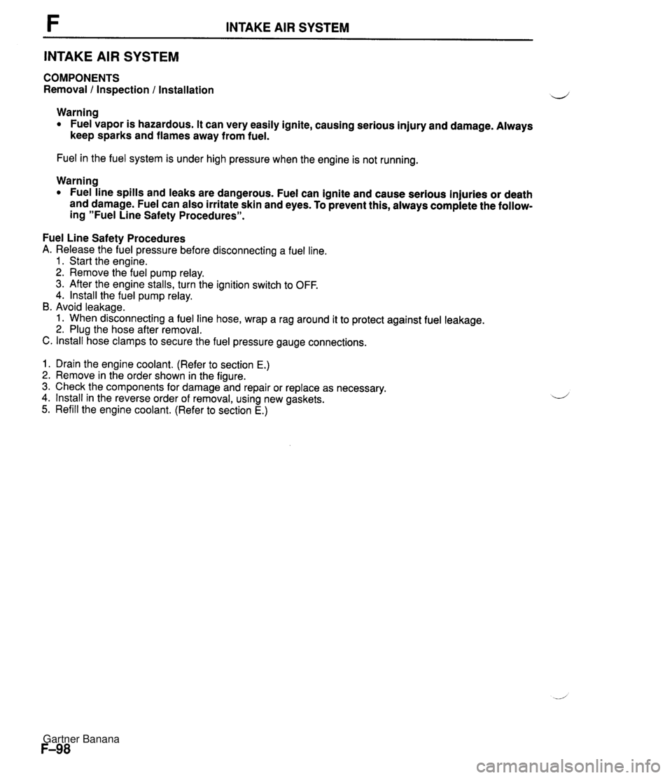
INTAKE AIR SYSTEM INTAKE AIR SYSTEM COMPONENTS Removal 1 Inspection l Installation Warning Fuel vapor is hazardous. It can very easily ignite, causing serious injury and damage. Always keep sparks and flames away from fuel. Fuel in the fuel system is under high pressure when the engine is not running. Warning Fuel line spills and leaks are dangerous. Fuel can ignite and cause serious injuries or death and damage. Fuel can also irritate skin and eyes. To prevent this, always complete the follow- ing "Fuel Line Safety Procedures". Fuel Line Safety Procedures A. Release the fuel pressure before disconnecting a fuel line. 1. Start the engine. 2. Remove the fuel pump relay. 3. After the engine stalls, turn the ignition switch to OFF. 4. lnstall the fuel pump relay. B. Avoid leakage. 1. When disconnecting a fuel line hose, wrap a rag around it to protect against fuel leakage. 2. Plug the hose after removal. C. lnstall hose clamps to secure the fuel pressure gauge connections. 1. Drain the engine coolant. (Refer to section E.) 2. Remove in the order shown in the figure. 3. Check the components for damage and repair or replace as necessary. 4. lnstall in the reverse order of removal, using new gaskets. 5. Refill the engine coolant. (Refer to section E.) Gartner Banana
Page 250 of 1708
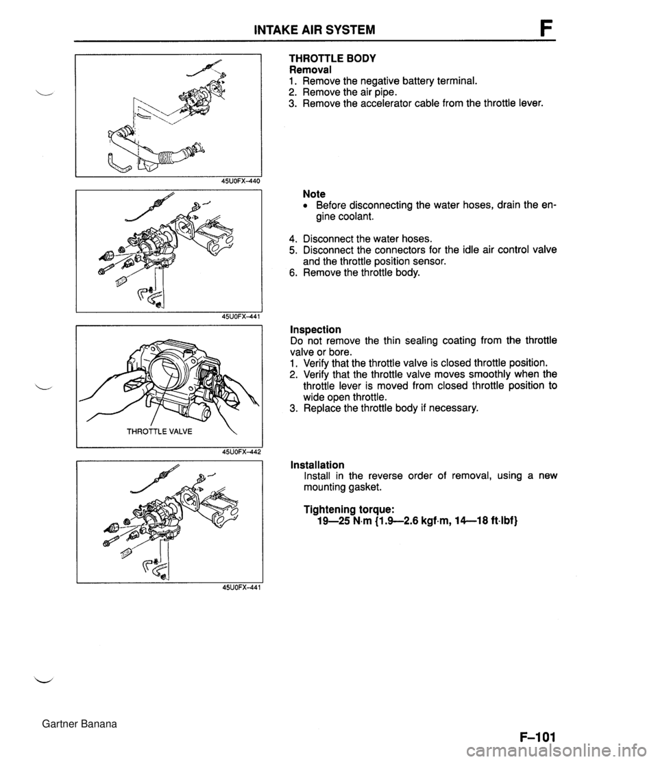
INTAKE AIR SYSTEM THROTTLE VALVE 45UOFX442 THROTTLE BODY Removal 1. Remove the negative battery terminal. 2. Remove the air pipe. 3. Remove the accelerator cable from the throttle lever. Note Before disconnecting the water hoses, drain the en- gine coolant. 4. Disconnect the water hoses. 5. Disconnect the connectors for the idle air control valve and the throttle position sensor. 6. Remove the throttle body. Inspection Do not remove the thin sealing coating from the throttle valve or bore. 1. Verify that the throttle valve is closed throttle position. 2. Verify that the throttle valve moves smoothly when the throttle lever is moved from closed throttle position to wide open throttle. 3. Replace the throttle body if necessary. Installation Install in the reverse order of removal, using a new mounting gasket. Tightening torque: 19-25 N.m (1.G2.6 kgf.m, 14--18 ftlbf) Gartner Banana
Page 253 of 1708
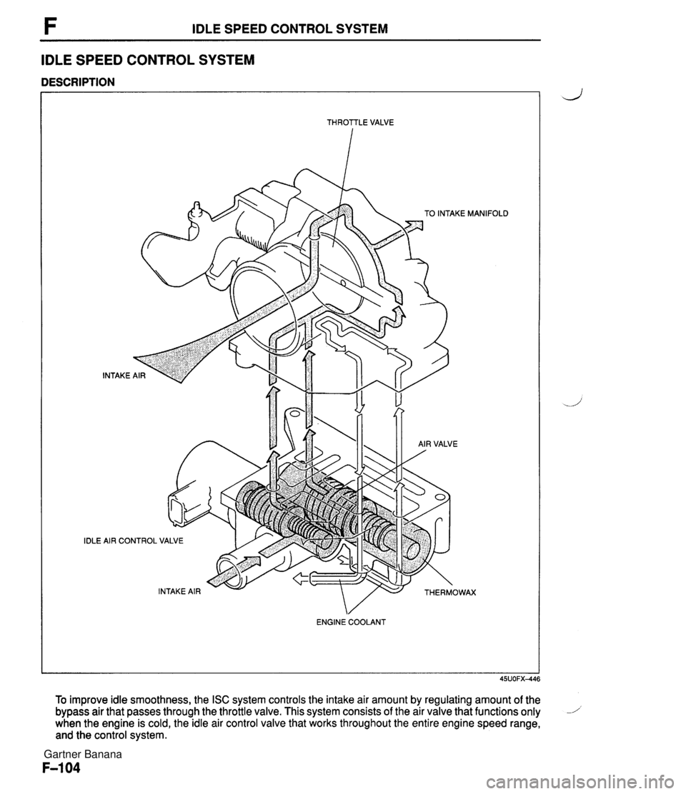
F IDLE SPEED CONTROL SYSTEM IDLE SPEED CONTROL SYSTEM DESCRIPTION - -- - THROTTLE VALVE IDLE TO INTAKE MANlF INTAKE i AIR CONTROL VALVE ENGINE COOLANT To improve idle smoothness, the ISC system controls the intake air amount by regulating amount of the bypass air that passes through the throttle valve. This system consists of the air valve that functions only 1 when the engine is cold, the idle air control valve that works throughout the entire engine speed range, and the control system. Gartner Banana
Page 254 of 1708
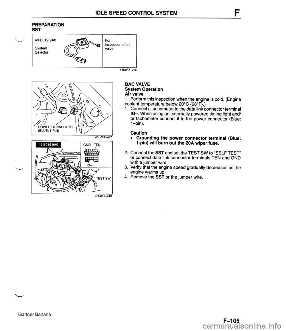
IDLE SPEED CONTROL SYSTEM PREPARATION SST I 'L 49 801 9 9AO For inspection of air System valve Selector BAC VALVE System Operation Air valve - Perform this inspection when the engine is cold. (Engine coolant temperature below 20°C {68OF).) 1. Connect a tachometer to the data link connector terminal IG-. When using an externally powered timing light and/ or tachometer connect it to the power connector (Blue: 1 -pin). Caution Grounding the power connector terminal (Blue: 1-pin) will burn out the 20A wiper fuse. 2. Connect the SST and set the TEST SW to "SELF TEST" or connect data link connector terminals TEN and GND with a jumper wire. 3. Verify that the engine speed gradually decreases as the engine warms up. 4. Remove the SST or the jumper wire. Gartner Banana