service MAZDA MX-5 1994 Workshop Manual
[x] Cancel search | Manufacturer: MAZDA, Model Year: 1994, Model line: MX-5, Model: MAZDA MX-5 1994Pages: 1708, PDF Size: 82.34 MB
Page 6 of 1708
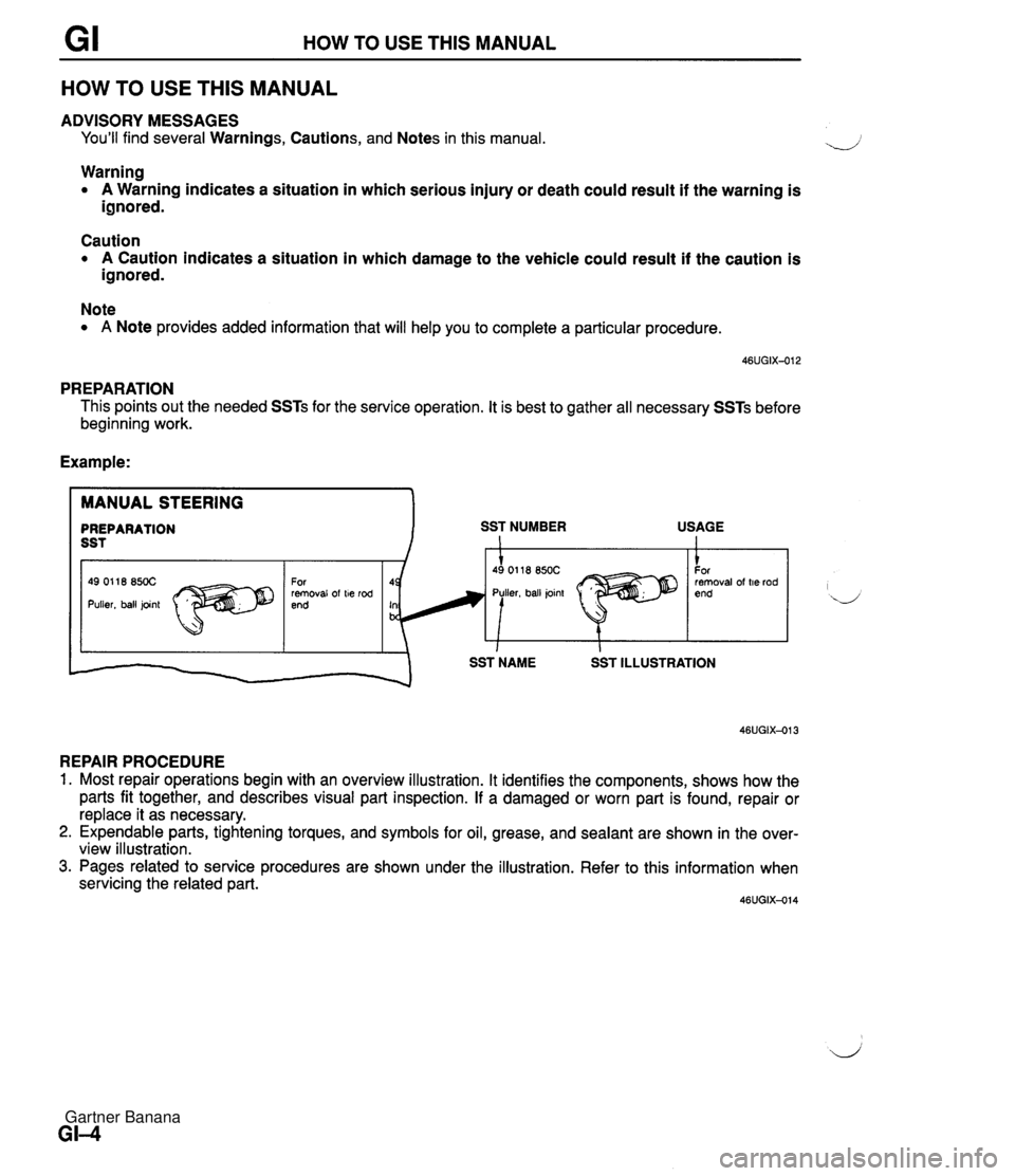
GI HOW TO USE THIS MANUAL HOW TO USE THlS MANUAL ADVISORY MESSAGES You'll find several Warnings, Cautions, and Notes in this manual. Warning A Warning indicates a situation in which serious injury or death could result if the warning is ignored. Caution A Caution indicates a situation in which damage to the vehicle could result if the caution is ignored. Note A Note provides added information that will help you to complete a particular procedure. PREPARATION This points out the needed SSTs for the service operation. It is best to gather all necessary SSTs before beginning work. Example: 46UGIX-013 REPAIR PROCEDURE MANUAL STEERING PREPARATION SST NUMBER USAGE SST 1 1 Most repair operations begin with an overview illustration. It identifies the components, shows how the parts fit together, and describes visual part inspection. If a damaged or worn part is found, repair or replace it as necessary. Expendable parts, tightening torques, and symbols for oil, grease, and sealant are shown in the over- view illustration. Pages related to service procedures are shown under the illustration. Refer to this information when servicing the related part. 46UGIX-014 I id' I SST NAME SST ILLUSTRATION For removal of t~e rod end 49 01 18 850C Puller, ball pnt 49 01 18 850C For removal of t~e rod end Gartner Banana
Page 7 of 1708
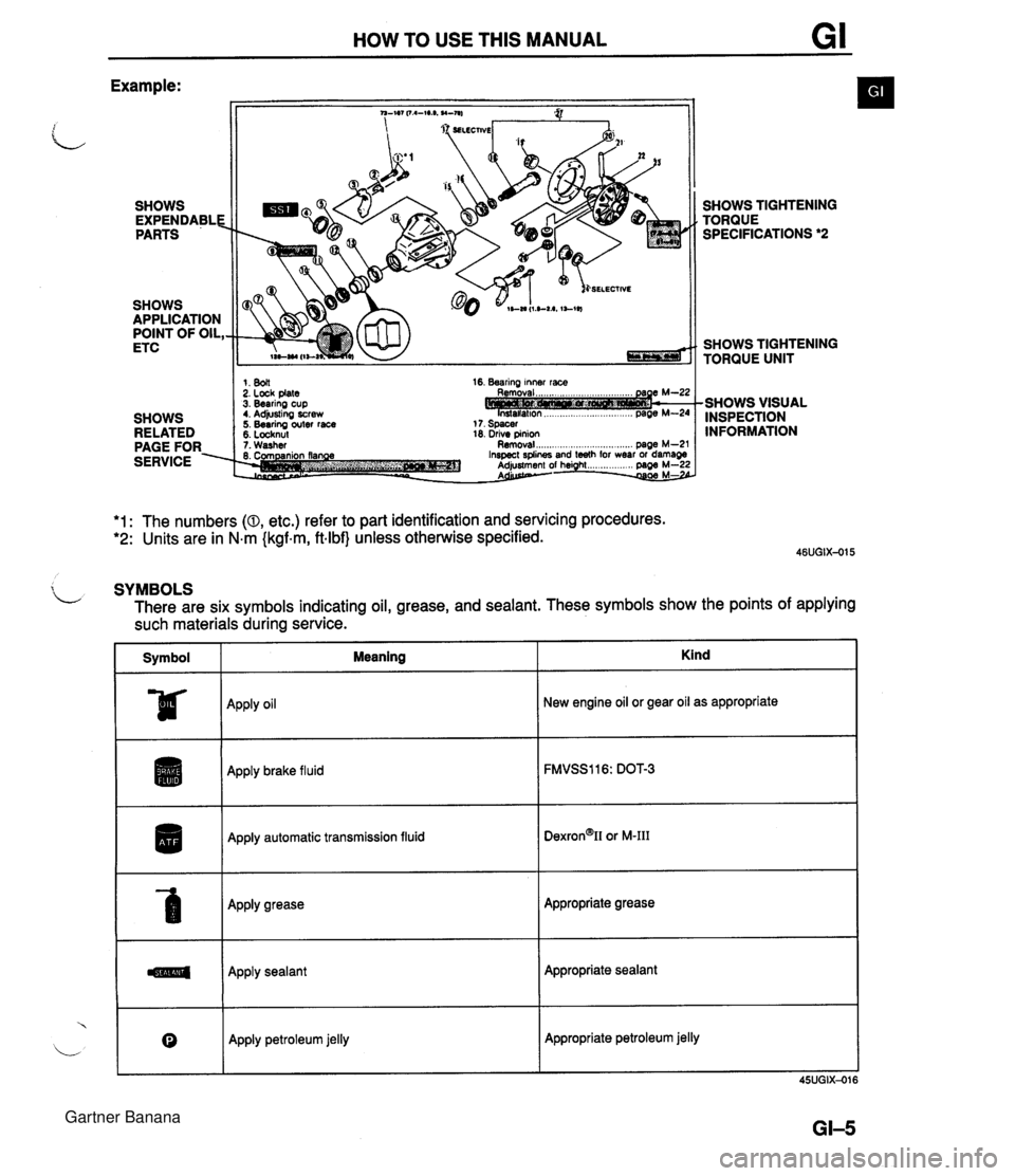
HOW TO USE THIS MANUAL Example: SHOWS EXPENDABLE PARTS SHOWS APPLICATION POINT OF OIL, ETC SHOWS RELATED PAGE FOR. SERVICE SELECTIVE 1. 8011 2. Lock plate 3. Bearing cup t. Adjusting screw 5. Bearing outer race 5. Locknul 16. Bearing inner race 18. drive pinion 1. Washer Removal ..................... .. .... page M-2' SHOWS TIGHTENING TORQUE SPECIFICATIONS *2 SHOWS TIGHTENING TORQUE UNIT -SHOWS VISUAL INSPECTION INFORMATION *1: The numbers (0, etc.) refer to part identification and servicing procedures. *2: Units are in N.m {kgf.m, ftlbf} unless otherwise specified. $ L SYMBOLS There are six symbols indicating oil, grease, and sealant. These symbols show the points of applying such materials during service. Symbol I Meaning ~pp~y oil Apply brake fluid I Apply automatic transmission fluid Apply grease Apply sealant Kind 0 New engine oil or gear oil as appropriate Apply petroleum jelly Appropriate grease Appropriate sealant Appropriate petroleum jelly Gartner Banana
Page 9 of 1708
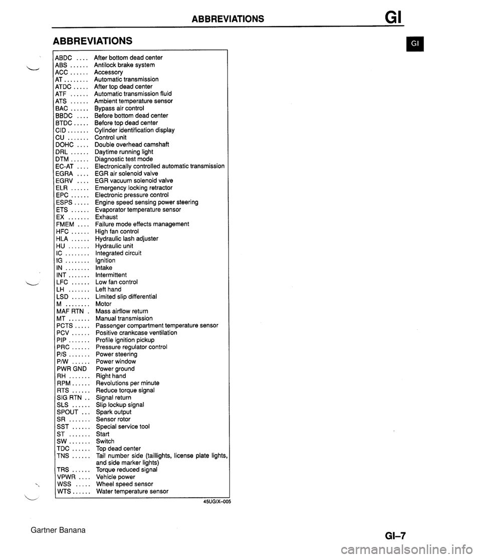
ABBREVIATIONS 4BDC .... 4BS ...... 4CC ...... 4T ........ 4TDC ..... 4TF ...... 4TS ...... 3AC ...... 3BDC .... 3TDC ..... :ID ....... 2U ....... IOHC .... IRL ...... ITM ...... IC-AT .... iGRA .... EGRV .... ELR ...... EPC ...... ESPS ..... ETS ...... EX ....... FMEM .... HFC ...... HLA ...... H U ....... IC ........ IG ........ IN ........ INT ....... LFC ...... LH ....... LSD ...... M ........ MAF RTN . MT ....... PCTS ..... PCV ...... PIP ....... PRC ...... PIS ....... PMI ...... PWR GND RH ....... RPM ...... RTS ...... SIG RTN . . SLS ...... ... SPOUT S R ....... SST ...... ST ....... SW ....... TDC ...... TNS ...... TRS ...... VPWR .... WSS ..... WTS...... After bottom dead center Antilock brake system Accessory Automatic transmission After top dead center Automatic transmission fluid Ambient temperature sensor Bypass air control Before bottom dead center Before top dead center Cylinder identification display Control unit Double overhead camshaft Daytime running light Diagnostic test mode Electronically controlled automatic transmission EGR air solenoid valve EGR vacuum solenoid valve Emergency locking retractor Electronic pressure control Engine speed sensing power steering Evaporator temperature sensor Exhaust Failure mode effects management High fan control Hydraulic lash adjuster Hydraulic unit Integrated circuit Ignition Intake Intermittent Low fan control Left hand Limited slip differential Motor Mass airflow return Manual transmission Passenger compartment temperature sensor Positive crankcase ventilation Profile ignition pickup Pressure regulator control Power steering Power window Power ground Right hand Revolutions per minute Reduce torque signal Signal return Slip lockup signal Spark output Sensor rotor Special service tool Start Switch Top dead center Tail number side (taillights, license plate lights and side marker lights) Torque reduced signal Vehicle power Wheel speed sensor Water temperature sensor Gartner Banana
Page 11 of 1708
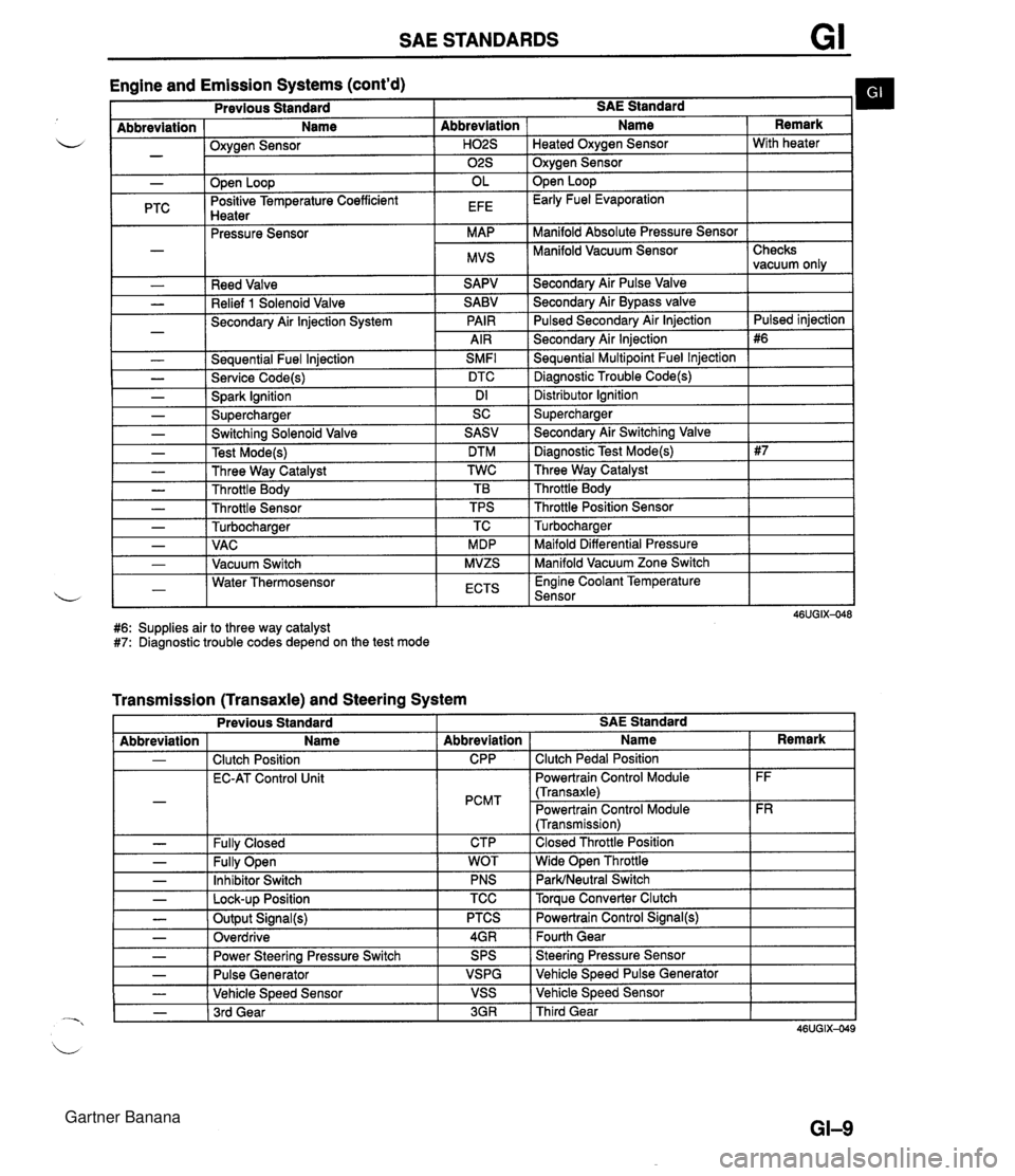
SAE STANDARDS Engine and Emission Systems (cont'd) I Previous Standard I SAE Standard b I - Abbreviation ( Name I Oxvaen Sensor - .w- - I I ." I 02s I Oxygen Sensor I - PTC Reed Valve Relief 1 Solenoid Valve Secondary Air lnjection System - Seauential Fuel lniection SMFl L - Service Code(s) DTC - Spark Ignition Dl - Supercharger SC Abbreviation I Name Open Loop Positive Temperature Coefficient Hnatar Secondarv Air Pulse Valve Remark . .--.-. Pressure Sensor Secondary Air Bypass valve Pulsed Secondarv Air lniection H02S I Heated Oxvaen Sensor I With heater OL EFE Secondary Air lnjection Sequential Multipoint Fuel lnjection Diagnostic Trouble Code(s) Open Loop Early Fuel Evaporation MAP MVS Distributor lgnition Supercharger Manifold Absolute Pressure Sensor Manifold Vacuum Sensor I - - - - - - Checks vacuum only Pulsed iniection - Switching Solenoid Valve Test Mode(s) Three Way Catalyst Throttle Body Throttle Sensor Turbocharaer .. Maifold Differential Pressure Manifold Vacuum Zone Switch , - I - 1 VAC I MDP 1-1 Water Thermosensor L - I Vacuum Switch I ECTS I Engine Coolant Temperature Sensor I SASV DTM TWC TB TPS TC MVZS #6: Supplies air to three way catalyst #7: Diagnostic trouble codes depend on the test mode - Secondary Air Switching Valve Diagnostic Test Mode(s) Three Way Catalyst Throttle Body Throttle Position Sensor Turbocharaer Transmission (Transaxle) and Steering System L - - Previous Standard I I I I Abbreviation - - - SAE Standard Fully Open Inhibitor Switch - I Lock-up Position - - Name Clutch Position EC-AT Control Unit Fullv Closed Abbreviation CPP PCMT CTP TCC I Torque Converter Clutch - - - WOT PNS Output Signal(s) Overdrive I Name Clutch Pedal Position Powertrain Control Module (Transaxle) Powertrain Control Module (Transmission) Closed Throttle Position Wide Open Throttle ParWNeutral Switch Power Steering Pressure Switch Pulse Generator Vehicle Speed Sensor - 1 3rd Gear Remark FF FR PTCS 4GR 3GR I Third Gear Powertrain Control Signal(@ Fourth Gear SPS VSPG VSS Steering Pressure Sensor Vehicle Speed Pulse Generator Vehicle Speed Sensor Gartner Banana
Page 17 of 1708
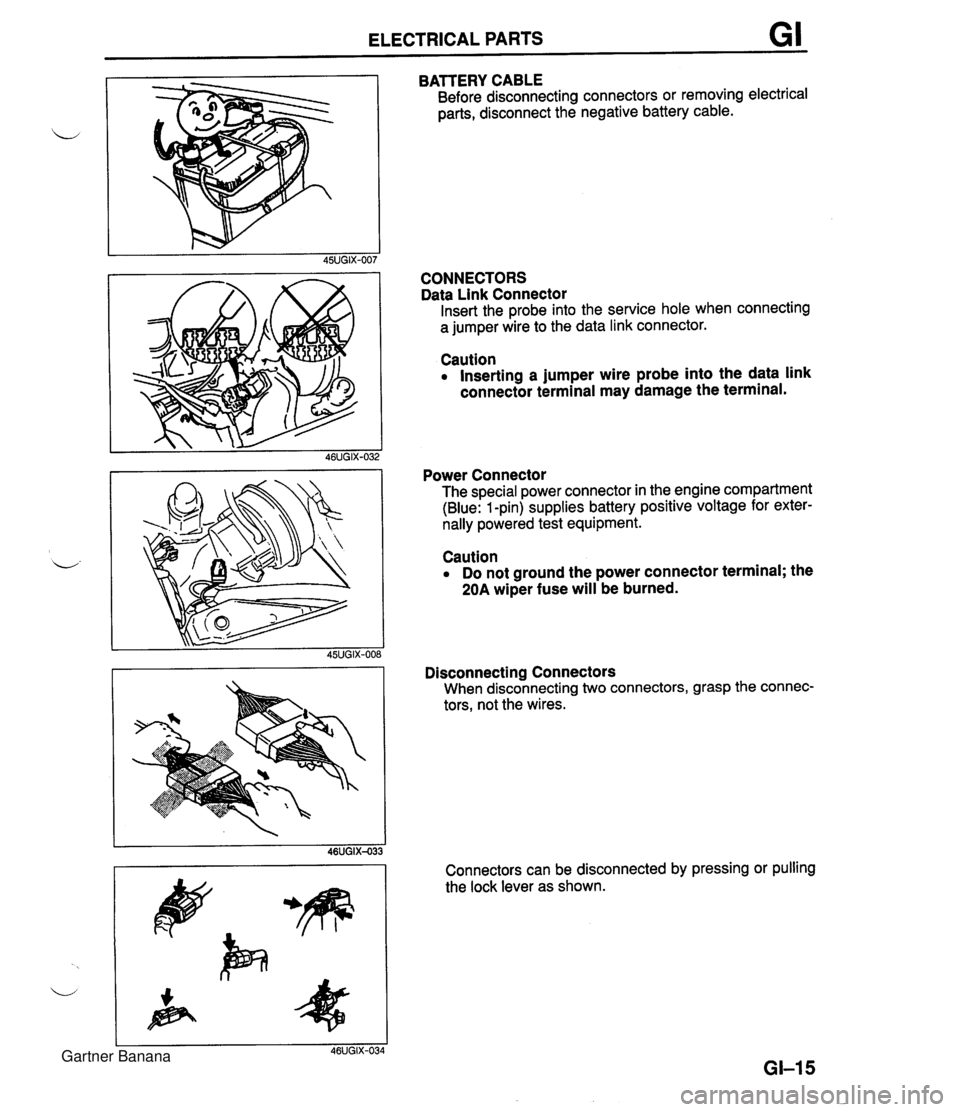
ELECTRICAL PARTS GI BATTERY CABLE Before disconnecting connectors or removing electrical parts, disconnect the negative battery cable. CONNECTORS Data Link Connector Insert the probe into the service hole when connecting a jumper wire to the data link connector. Caution Inserting a jumper wire probe into the data link connector terminal may damage the terminal. Power Connector The special power connector in the engine compartment (Blue: 1 -pin) supplies battery positive voltage for exter- nally powered test equipment. Caution Do not ground the power connector terminal; the 20A wiper fuse will be burned. Disconnecting Connectors When disconnecting two connectors, grasp the connec- tors, not the wires. Connectors can be disconnected by pressing or pulling the lock lever as shown. Gartner Banana
Page 26 of 1708
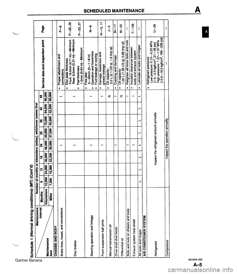
Schedule 1 (Normal driving conditions) (MT) (Cont'd) Maintenance 1 Number of months or kilometers {miles), whichever comes first I I 1 Months 1 6 18 124 130 136 142148 Service data and inspection point 36,000 1 48,000 1 60,000 1 72,000 1 84,000 1 96,000 Maintenance item I CHASSIS AND BODY Brake lines, hoses, and connections Disc plate thickness Front: 18.0mm (0.71 in)--Minimum I I 1 near: 8.0mm {o31 inFMnimum P-6 I Disc brakes I Pad thickness: I I I I I ~10mrn~0.04inMlinimum I Proper attachment and connections Steering operation and linkage I I I I I I I 0-3'0mm (0-1.1 8 in) Operation and looseness Fluid leakaae or oozina I I Front suspension ball joints I I Free play: I I I I I I I - - Manual transmission oil I I I I I , I Damage, looseness and I grease leakage Oil capacity: 2.0 L (2.1 US at. 1.8 Imp qtJ Ill I I I I I Cracking and damage I , I Oil capacity: I I I Differential oil I Drive shaft dust boots I Bolts and nuts on chassis and body I I I n I 1 .OO L {I .06 US qt, 0.88 Imp qt} Ill Exhaust system heat shield I I I I 1 Retiahten all loose bolts and nuts L All locks and hinges lLlLl - AIR CONDITIONER SYSTEM I L Refrigerant pressure Low pressure: 0.1 5-0.25 MPa {I -52.5 kgf/cm2, 21-36 psi) High pressure: 1.37-1 -57 MPa {I 4.0-1 6.0 kgf/cm2, 1 XI-228 psi] - L Corn~ressor I lnswct the o~eration annuallv Refrigerant L Inspect the refrigerant amount annually L I L " Insulator clearance between body and exhaust system Lubricate all locks and hinges F-128 - Gartner Banana
Page 28 of 1708
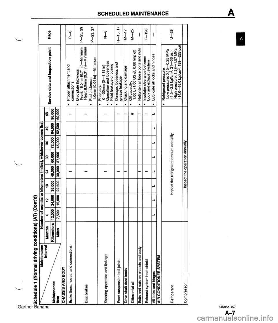
Schedule 1 (Normal driving conditions) (AT) (Cont'd) - .. .. Brake lines, hoses, and connections -- Front suspension ball joints Page I Disc brakes Steering operation and linkage I I 1 I I I I Drive shaft dust boots Ill CHASSIS AND BODY Service data and inspection point Maintenance Number of months or kilometers {miles), whichever comes first I I Differential oil I interval Months Maintenance Kilometers item Miles Exhaust system heat shield I 36 72,000 45,000 I I I I I I I I I 1 I I I I All locks and hinaes lLlLlLlLlLlLlL 6 12,000 7,500 Bolts and nuts on chassis and body - AIR CONDIIONER SYSTEM 42 84,000 52,500 I Ill 12 24,000 15,000 96,000 60,000 Proper attachment and connections Disc plate thickness Front: 18.0mm (0.71 in)-Minimum Rear: 8.0mm f0.31 in)--Minimum Pad thickness: 1 .Omm 10.04 inl-Minimum .-- Free play: C-30mm (0-1 .I 8 in) Operation and looseness Fluid leakage or oozing 18 36,000 22,500 Refrigerant Compressor Damage, looseness and arease leakaae Inspect the refrigerant amount annually Inspect the operation annually 24 48,000 30,000 30 60,000 37,500 Cracking and damage Oil capacity: 1 .OO L 11.06 US at. 0.88 Irn~ at} M-17 M-25 Retighten all loose bolts and nuts Insulator clearance between bodv and exhaust system Refrigerant pressure Low pressure: 0.1 5-0.25 MPa (1 .5-2.5 kgf/:, 21-36 psi) 1 LJ: High pressure: 1.37-1.57 MPa {I 4.0-1 6.0 kgf/cm2, 194--228 psi) - F-128 Lubricate all locks and hinges - Gartner Banana
Page 31 of 1708

2 (Unique driving conditions) (MT) (Cont'd) Number of months or kilometers miles), whichever comes first 24 28 32 36 40 44 48 48 56 64 72 80 88 96 Service data and inspection point Page Maintenance interval Maintenance item .# CHASSIS AND BODY Proper attachment and connections Brake lines, hoses, and connections IIII Disc brakes I Steering operation and linkage Disc plate thickness Front: 18.0mm (0.71 inkMinimum Rear: 8.0mm I0.31 in)--Minimum Pad thickness: 1 .Omm 10.04 inbMinimum Free play: O-30mm {0-1.18 in) Operation and looseness Fluid leakage or oozing Front suspension ball joints 1111 Damage, looseness and arease leakaae I I I I Drive shaft dust boots Cracking and damage Manual transmission oil Oil capacity: 2.0 L (2.1 US at, 1.8 I~D at1 Differential oil Oil capacity: 1 .OO L(1.06 US qt, 0.88 Imp qt} Retighten all loose bolts and nuts I I I Bolts and nuts on chassis and body Exhaust system heat shield Insulator clearance between bodv and exhaust svstem I I I I All locks and hinges ILlLlLlL Lubricate all locks and hinges - I AIR CONDITIONER SYSTEM ~p - ~-~p- Refrigerant Inspect the refrigerant amount annually Refrigerant pressure Low pressure: 0.1 5-0.25 MPa {I S-2.5 kgf/cm2, 21 -36 psi} High pressure: 1.37-1 57 MPa (1 4.0-1 6.0 kgf/cm2, 194-228 psi) Comoressor I lnsoect the ooeration annuallv I I - Gartner Banana
Page 32 of 1708
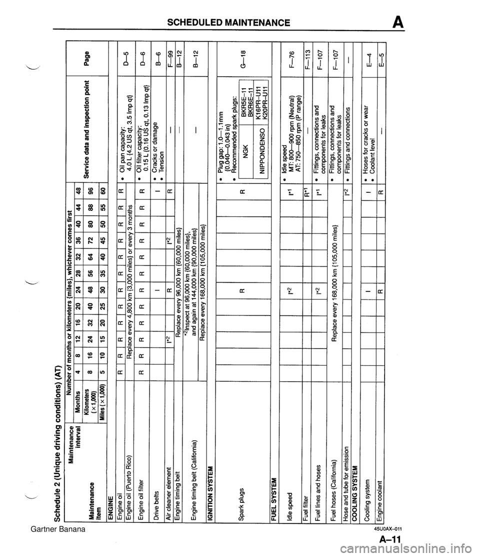
Schedule 2 (Unique driving conditions) (AT) Maintenance interval Maintenance item ENGINE Engine oil I R I R I R I R I R I R I R I R I R I R I R I R Engine oil filter Drive belts Number of months or kilometers {miles}, whichever comes first eoilpancapacity: 4.0 L {4.2 US qt, 3.5 Imp qt} Engine oil (Puerto Rico) I I IGNITION SYSTEM Service data and inspection point Months Kilometers (x 1,m) Miles (x 1,000) D-5 Replace every 4,800 km (3,000 miles) or every 3 months I I I I I I I I - - Engine timing belt (California) Spark plugs Page - - Air cleaner element I I FUEL SYSTEM 4 8 5 I F-99 8-1 2 -. . . '21nspect at 96,000 km {60,000 miles}, and again at 144,000 km {90,000 miles) Replace every 168,000 km (1 05,000 miles) - - R*' - 1'1 l Oilfiltercapacity: 0.15 L (0.16 US qt, 0.13 Imp qt} l Cracks or damage l Tension I R 1 Ie2 1 Engine timing belt ~ --- - - l Plug gap: 1 .&I -1 mm (0.040-4.043 in) l Recommended dark ~luas: 8 16 10 D-6 B-6 Replace every 96,000 km (60,000 miles) Idle speed Fuel filter Fuel lines and hoses NGK , BKRGE-11 BKR5E-I 1 12 24 15 IRI I*2 lt2 l Idle speed MT: 800-900 rpm (Neutral) 1 F-76 AT: 75M0 rpm (P range) 16 32 20 I!*'2 1 20 40 25 24 48 30 - Fittings, connections and com~onents for leaks 36 72 45 F-113 F-1 07 Fuel hoses (California) Hose and tube for emission 28 56 35 Cooling system Engine coolant 32 64 40 COOLING SYSTEM Replace every 168,000 km {I 05,000 miles} 1 1*2 48 96 60 40 80 50 I R 44 88 55 l Fittings, connections and components for leaks Fittings and connections F-1 07 - I R l Hoses for cracks or wear l Coolant level - E4 E-5 Gartner Banana
Page 33 of 1708

I Brake lines. hoses, and connections Ill Schedule 2 (Unique driving conditions) (AT) (Cont'd) Disc brakes Steering operation and linkage I Front suspension ball joints 111 Page I Drive shaft dust boots I I I CHASSIS AND BODY Service data and inspection point Maintenance Number of months or kilometers {miles}, whichever comes first I Differential oil 111 I Bolts and nuts on chassis and body 111 48 96 60 I Exhaust system heat shield Ill interval Months Kilometers Maintenance (x1,OOO) Miles(x1,OOO) All locks and hinges AIR CONDIVONER SYSTEM 12 24 15 4 8 5 Disc plate thickness Front: 18.0mm (0.71 in)-Minimum Rear: 8.0mm i0.31 in)-Minimum Pad thickness: 1 .Omm (0.04 in)--Minimum Free play: 0-30mm {O-1 .I 8 in} Operation and looseness Fluid leakage or oozing 16 32 20 8 16 10 P--6 I l Oil capacity: I I I I 1 I 1.00 L 11-06 US at. 0.88 lm~ at I M-25 l Proper attachment and connections I I I I I I I I 7, .' , Ill I 1 I I Retighten all loose bolts and nuts I - 20 40 25 l Damage, looseness and grease leakage Cracking and damage Insulator clearance between I I I I I1Iob odv and exhaust svstem 28 56 35 24 48 30 L 1 L I L I L 1 L 1 L 1 Lubricatealllocksandhinges I - Refrigerant 32 64 40 Inspect the refrigerant amount annually 36 72 45 l Refrigerant pressure Low pressure: 0.1 5-0.25 MPa (1.5-2.5 kgf/cm2, 21-36 psi} High pressure: 1.37-1 57 MPa {I 4.0-1 6.0 kgfld, 19%-228 psi] - I 40 80 50 Compressor 44 88 55 Inspect the operation annually Gartner Banana