audio MAZDA MX-5 1994 Workshop Manual
[x] Cancel search | Manufacturer: MAZDA, Model Year: 1994, Model line: MX-5, Model: MAZDA MX-5 1994Pages: 1708, PDF Size: 82.34 MB
Page 3 of 1708

GENERAL INFORMATION SAFETY INFORMATION ...................... GI- 2 LUBRICANTS .............................. GI- 2 JACKING POSITIONS ...................... GI- 2 SAFETY STAND POSITIONS ................ GI- 2 VEHICLE LIFT POSITIONS .................. GI- 3 DYNAMOMETER ........................... GI- 3 COMPRESSED AIR ........................ GI- 3 HOW TO USE THIS MANUAL ................. GI- 4 ADVISORY MESSAGES .................... GI- 4 PREPARATION ............................ GI- 4 REPAIR PROCEDURE ...................... GI- 4 SYMBOLS ................................. GI- 5 IDENTIFICATION NUMBER LOCATIONS ....... GI- 6 UNITS ...................................... GI- 6 ABBREVIATIONS ............................ GI- 7 SAE STANDARDS ........................... GI- 8 FUNDAMENTAL PROCEDURES ............... GI-11 PROTECTION OF THE VEHICLE ............ GI-11 PREPARATION OF TOOLS AND MEASURING EQUIPMENT ............................. GI-11 SPECIAL TOOLS ........................... GI-11 REMOVALOF PARTS ...................... GI-11 DISASSEMBLY ............................ GI-11 REASSEMBLY ............................. GI-1 2 ADJUSTMENTS ............................ GI-13 RUBBER PARTS AND TUBING .............. GI-13 HOSE CLAMPS ............................ GC13 TORQUE FORMULAS ...................... GI-13 VISE ...................................... GI-13 ELECTRICAL TROUBLESHOOTING TOOLS ... GI-14 TEST LIGHT ............................... GI-14 JUMPER WIRE ............................ GC14 VOLTMETER .............................. GI-14 OHMMETER ............................... GI-14 ELECTRICAL PARTS ......................... GI-1 4 BATTERY ................................. GI-1 4 BATTERY CABLE .......................... GI-1 5 CONNECTORS ............................ GI-15 TERMINALS ............................... GI-16 SENSORS. SWITCHES. AND RELAYS ....... GI-17 WIRING HARNESS ......................... GI-17 FUSE ..................................... GI-17 INSTALLATION OF MOBILE TWO-WAY RADIO SYSTEM ................................... GI-18 AUDIO ANTITHEFT SYSTEM ................. GI-18 TOWING .................................... GI-19 45UGIX-001 Gartner Banana
Page 20 of 1708

G I INSTALLATION OF MOBILE TWO-WAY RADIO SYSTEMIAUDIO ANTITHEFT SYSTEM INSTALLATION OF MOBILE TWO-WAY RADIO SYSTEM If a mobile two-way radio system is installed improperly or if a high-powered type is used, the CIS and other systems may be affected. L-.) When the vehicle is to be equipped with a mobile two-way radio, observe the following precautions: 1. lnstall the antenna at the farthest point from control units. 2. Install the antenna feeder as far as possible from the control unit harnesses (at least 30 cm (11.8 in)). 3. Ensure that the antenna and feeder are properly adjusted. 4. Do not install a hiah-h owe red mobile two-wav radio svstem. FEEDER W!RE CONTROL UNIT HARNESS AT LEAST 30 cm (11.8 in) 46UGIX-043 AUDIO ANTITHEFT SYSTEM An audio with an antitheft function is optionally available. Before removing the negative battery terminal or discon- necting the audio power source, obtain the code number and deactivate the audio antitheft system. (Refer to section T.) Gartner Banana
Page 23 of 1708

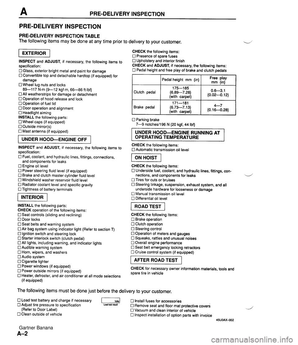
PRE-DELIVERY INSPECTION PRE-DELIVERY INSPECTION PRE-DELIVERY INSPECTION TABLE The following items may be done at any time prior to delivery to your customer. INSPECT and ADJUST, if necessary, the following items to specification: 0 Glass, exterior bright metal and paint for damage 0 Convertible top and detachable hardtop (if equipped) for damage 0 Wheel lug nuts and locks 89-117 N.m (9-1 2 kgf.m, 66-86 ft4bf) 0 All weatherstrips for damage or detachment Operation of hood release and lock Operation of fuel lid 0 Door operation and alignment Headlight aiming INSTALL the following parts: Wheel caps (if equipped) 0 Outside mirror(s) 0 Mast antenna (if equipped) UNDER HOOD-ENGINE OFF INSPECT and ADJUST, if necessary, the following items to specification : Fuel, coolant, and hydraulic lines, fittings, connections, and components for leaks Engine oil level 0 Power steering fluid level (if equipped) Brake and clutch master cylinder fluid level 0 Windshield washer reservoir fluid level 0 Radiator coolant level and specific gravity 0 Tightness of battery terminals pKiq INSTALL the following parts: CHECK operation of the following items: 0 Seat controls (sliding and reclining) 0 Door locks 0 Seat belts and warning system 0 Air bag system using indicator light (Refer to section T) Ignition switch and steering lock 0 Starter interlock switch (clutch pedal) All lights, including warning, and indicator lights 0 Audible warning system 0 Horn, wipers, and washers Audio system 0 Cigarette lighter Power windows (if equipped) 0 Power outside mirrors (if equipped) 0 Heater, defroster, and air conditioner at all mode selections (if equipped) CHECK the following items: Presence of spare fuses 0 Upholstery and interior finish CHECK and ADJUST, if necessary, the following items: 0 Pedal height and free play of brake and clutch pedals I Pedal height mm {in} I Ft: $iy I Clutch pedal {6.89--7.28) (with carpet) Parking brake 7-9 notchesil96 N (20 kgf, 44 Ibf) 0.63.1 (0.024. 12) Brake pedal RUNNING AT OPERATING TEMPERATURE CHECK the following items: 0 Automatic transmission oil level 171-181 (6.73--7.13) (with carpet) I ON HOIST I 4--7 {0.16-0.28} CHECK the following items: 0 Underside fuel, coolant, and hydraulic lines, fittings, con- nections, and components for leaks 4 Tires for cuts or bruises 0 Steering linkage, suspension, exhaust system, and all underside hardware for looseness or damage Manual transmission oil level Differential oil level I ROAD TEST I CHECK the following items: Brake operation Clutch operation 0 Steering control 0 Operation of meters and gauges Squeaks, rattles and unusual noises 0 Overall engine performance Seat belt emergency locking retractors 0 Cruise control system (if equipped) I AFTER ROAD TEST I CHECK for necessary owner information materials, tools and spare tire in vehicle The following items must be done just before the delivery to your customer. 0 Load test battery and charge if necessary -1 Install fuses for accessories Adjust tire pressure to specification Load test fesuk 0 Remove seat and floor mat protective covers (Refer to Door Label) 0 Vacuum and clean interior of vehicle Clean outside of vehicle Inspect installation of option parts with invoice 45UOAX-002 Gartner Banana
Page 38 of 1708

Before beginning any service procedure. refer to section T of this manual for air bag system service warnings and audio antitheft system alarm conditions . ENGINE INDEX ............................. B- 2 OUTLINE .......................... B- 3 SPECIFICATIONS ................ B- 3 TROUBLESHOOTING GUIDE ........ B- 3 ENGINE TUNE-UP .................. 8- 5 PREPARATION ................... B- 5 ENGINE OIL ..................... B- 5 ENGINE COOLANT ............... B- 5 DRIVE BELT ..................... 8- 6 HLA TROUBLESHOOTING GUIDE . 8- 8 IGNITION TIMING. IDLE SPEED .... B- 8 COMPRESSION .................... 8-10 INSPECTION ..................... B-10 ON-VEHICLE MAINTENANCE ....... B-11 PREPARATION ................... B-11 TIMING BELT ..................... 8-12 CYLINDER HEAD GASKET ........ B-16 H LA ............................. 8-20 FRONT OIL SEAL ................. 8-24 REAR OIL SEAL .................. 8-26 REMOVAL ......................... 8-28 PROCEDURE .................... B-28 ENGINE STAND MOUNTING ......... 8-32 PREPARATION ................... 8-32 PROCEDURE .................... B-33 DISASSEMBLY ..................... B-35 PREPARATION ................... 8-35 AUXILIARY PARTS ............... 8-36 TIMING BELT ..................... 8-37 CYLINDER HEAD ................. 8-39 CYLINDER BLOCK (EXTERNAL PARTS) ............. 8-42 CYLINDER BLOCK .............. (INTERNAL PARTS) 8-44 .............. INSPECTION I REPAIR 8-47 ................... PREPARATION 8-47 ................. CYLINDER HEAD 8-47 .............. VALVE MECHANISM 8-48 ...................... CAMSHAFT B-51 HLA ............................. 8-53 ............... CYLINDER BLOCK B-53 .......................... OIL JET B-54 PISTON. PISTON RING. AND ..................... PISTON PIN 8-55 CONNECTING ROD .............. B-56 ................... CRANKSHAFT 8-57 BEARING ........................ 8-57 TIMING BELT ..................... 8-58 TENSIONER. IDLER .............. 8-58 TENSIONER SPRING ............. 8-58 PULLEY ......................... 8-58 ........................ ASSEMBLY 8-59 ................... PREPARATION 8-59 CYLINDER BLOCK (INTERNAL PARTS) .............. B-60 CYLINDER BLOCK (EXTERNAL PARTS) ............. B-65 CYLINDER HEAD ................. B-69 TIMING BELT ..................... 8-73 ............... AUXILIARY PARTS 8-77 ..... ENGINE STAND DISMOUNTING 8-81 .................... PROCEDURE 8-81 INSTALLATION ..................... 8-83 .................... PROCEDURE 843 45UOBX-001 Gartner Banana
Page 124 of 1708

Before beginning any service procedure. refer to section T of this manual for air bag system service warnings and audio antitheft system alarm conditions . LUBRICATION SYSTEM INDEX ....................................... D- 2 ..................................... OUTLINE D- 3 ........................... SPECIFICATIONS D- 3 TROUBLESHOOTING GUIDE .................. D- 3 OIL PRESSURE .............................. D- 4 PREPARATION ............................. D- 4 INSPECTION ............................... D- 4 ENGINE OIL .................................. D- 5 INSPECTION ............................... D- 5 REPLACEMENT ............................ D- 5 OIL FILTER ................................... D- 6 REPLACEMENT ............................ D- 6 OIL COOLER ................................. D- 7 REMOVAL / INSTALLATION .................. D- 7 OIL PAN ..................................... D- 8 REMOVAL / INSTALLATION .................. D- 8 OIL PUMP .................................... D-11 DISASSEMBLY / ASSEMBLY ................. D-11 INSPECTION ............................... D-12 45UODX401 Gartner Banana
Page 137 of 1708

- . - . Before beginning any service procedure, refer to section T of this manual for air bag system service warnings and audio antitheft system alarm conditions . COOLING SYSTEM INDEX ....................................... E- 2 OUTLINE ..................................... E- 3 SPECIFICATIONS ........................... E- 3 TROUBLESHOOTING GUIDE .................. E- 3 ENGINE COOLANT ........................... E- 4 PREPARATION ............................. E- 4 INSPECTION ............................... E- 4 REPLACEMENT ............................ E- 5 REFILLING ................................. E- 6 .............................. RADIATOR CAP E- 7 ............................. PREPARATION E- 7 INSPECTION ............................... E- 7 RADIATOR ................................... E- 8 REMOVAL I INSTALLATION .................. E- 8 INSPECTION ............................... E- 8 THERMOSTAT ................................ E- 9 REMOVAL I INSTALLATION .................. E- 9 INSPECTION ............................... E- 9 WATER PUMP ................................ E-10 REMOVAL / INSTALLATION .................. E-10 COOLANT FAN MOTOR ....................... E-12 INSPECTION ............................... E-12 REPLACEMENT ............................ E-12 ........................ COOLANT FAN RELAY E-13 ............................... INSPECTION E-13 45UOEX-001 Gartner Banana
Page 150 of 1708

Before beginning any service procedure. refer to section T of this manual for air bag system service warnings and audio antitheft system alarm conditions . FUEL AND EMISSION CONTROL SYSTEMS INDEX ............................ F- 2 ......................... OUTLINE F- 5 .............. SYSTEM DIAGRAM F- 5 VACUUM HOSE ROUTING DIAGRAM ...................... F- 6 WIRING DIAGRAM ............... F- 7 SPECIFICATIONS ............... F- 8 COMPONENT DESCRIPTIONS ... F- 9 ....... TROUBLESHOOTING GUIDE F- 11 ENGINE CONTROL OPERATION CHART ........................ F- 11 RELATIONSHIP CHART .......... F- 12 USING THIS SECTION ........... F- 13 DIAGNOSTIC INDEX ............. F- 15 SYMPTOM TROUBLESHOOTING . F- 17 PREPARATION ................... F- 75 ............. BASIC INSPECTION F- 75 .................. ADJUSTMENT F- 76 ON-BOARD DIAGNOSIS SYSTEM . . F- 78 DESCRIPTION .................. F- 78 PREPARATION .................. F- 79 DIAGNOSTIC TROUBLE CODE NUMBER ...................... F- 79 ... SWITCH MONITOR FUNCTION F- 95 INTAKE AIR SYSTEM .............. F- 98 COMPONENTS .................. F- 98 SYSTEM OPERATION ............ F-100 THROTTLE BODY ............... F-101 INTAKE MANIFOLD .............. F-102 ACCELERATOR PEDAL AND CABLE ........................ F-103 IDLE SPEED CONTROL SYSTEM ... F-104 DESCRI PTlON .................. F-104 PREPARATION .................. F-105 BAC VALVE ..................... F-105 IDLE AIR CONTROL VALVE ....... F-106 FUEL SYSTEM .................... F-107 DESCRIPTION .................. F-107 PREPARATION .................. F-108 SYSTEM OPERATION ............ F-109 FUEL TANK ..................... F-111 FUEL FILTER .................... F-113 FUEL PUMP .................... F-114 FUEL PUMP RELAY .............. F-117 PRESSURE REGULATOR ........ F-118 FUEL INJECTOR ................ F-119 PRESSURE REGULATOR CONTROL SYSTEM ......................... F-122 PRC SOLENOID VALVE .......... F-123 EXHAUST GAS RECIRCULATION (EGR) ........................... F-124 PREPARATION .................. F-124 .................. DESCRIPTION F-124 SYSTEM OPERATION F-125 ............ EGR SOLENOID VALVE (VACUUM) F-125 EGR SOLENOID VALVE (VENT) ... F-126 ......... EGR FUNCTION SENSOR F-126 ........... EGR CONTROL VALVE F-127 ................ EXHAUST SYSTEM F-128 .................. COMPONENTS F-128 OUTLINE OF EMISSION CONTROL ......................... SYSTEM F-129 ............. STRUCTURAL VIEW F-129 POSITIVE CRANKCASE VENTILATION ................... (PCV) SYSTEM F-130 ' DESCRIPTION .................. F-I ..................... PCV VALVE F-1 ..... FUEL EVAPORATIVE SYSTEM F- .................. DESCRIPTION F- ....... PURGE SOLENOID VALVE F- ........ TWO-WAY CHECK VALVE F- ...... THREE-WAY CHECK VALVE F- ............. FUEL VAPOR VALVE F- .......... CHARCOAL CANISTER F- CATALYTIC CONVERTER SYSTEM . F- .................. DESCRIPTION F- .......... THREE-WAY CATALYST F- AIC CUT-OFF CONTROL SYSTEM . . F- .................. DESCRIPTION F- ........... SYSTEM INSPECTION F- ...................... A/c RELAY F-1 36 ..... DECHOKE CONTROL SYSTEM F-137 .................. DESCRIPTION F-137 ......... COOLANT FAN CONTROL F-138 ....................... OUTLINE F-138 .................. COOLANT FAN F-139 ............... CONDENSER FAN F-139 ........... SYSTEM INSPECTION F-140 ........... COOLANT FAN RELAY F-140 ........ CONDENSER FAN RELAY F-140 ............... CONTROL SYSTEM F-141 .................. PREPARATION F-141 ............. STRUCTURAL VIEW F-142 POWERTRAIN CONTROL MODULE .............. (ENGINE) (PCME) F-143 ........ MASS AIRFLOW SENSOR F-152 CRANKSHAFT POSITION SENSOR F-153 ENGINE COOLANT TEMPERATURE ...................... SENSOR F-154 THROTTLE POSITION SENSOR . . F-154 HEATED OXYGEN SENSOR ...... F-156 MAIN RELAY .................... F-157 ............... CLUTCH SWITCH F-157 NEUTRAL SWITCH .............. F-157 STEERING PRESSURE SENSOR . F-158 45UOFX-001 Gartner Banana
Page 308 of 1708

Before beginning any service procedure. refer to section T of this manual for air bag system service warnings and audio antitheft system alarm conditions . ENGINE ELECTRICAL SYSTEM INDEX ....................................... G- 2 OUTLINE ..................................... G- 3 SPECIFICATIONS ........................... G- 3 TROUBLESHOOTING GUIDE .................. G- 4 CHARGING SYSTEM .......................... G- 6 PREPARATION ............................. G- 6 CIRCUIT DIAGRAM ......................... G- 6 TROUBLESHOOTING ....................... G- 7 BATTERY .................................. G- 8 ALTERNATOR .............................. G-10 DRIVE BELT ................................ G-13 IGNITION SYSTEM ............................ G-15 PREPARATION ............................. G-15 CIRCUIT DIAGRAM ......................... G-15 TROUBLESHOOTING ....................... G-16 IGNITION TIMING ........................... G-17 SPARK PLUG ............................... G-18 IGNITION COIL ............................. G-19 IGNITER ................................... G-19 HIGH-TENSION LEAD ....................... G-20 STARTING SYSTEM ........................... G-21 CIRCUIT DIAGRAM ......................... G-21 TROUBLESHOOTING ....................... G-21 STARTER .................................. G-22 STARTER INTERLOCK SWITCH (MT) ......... G-28 45UOGX401 Gartner Banana
Page 310 of 1708

OUTLINE OUTLINE SPECIFICATIONS (i.e. powertrain control module (engine), audio, etc.) *2 With System Selector (49 B019 9AO) test switch at SELF TEST. - Engine Item Starter Ignition system Cylinder Arrangement Battery BP DOHC MT I AT 12, Negative ground S46A24L(S) (32 Ah) Maintenance-free 20.0 A.C. I REAR Voltage V Type and capacity (5-hour rate) 12-65 -. 1 2-70 Drive belt deflection mm {in} Dark current" m A Transistorized (built-in voltage regulator) 14.3-1 4.9 21.5 I0.846) 8 (0.31 1 Ignition timing** BTDC ("CA)lrpm U Alternator 'I Dark current is the constant flow of current while the ignition switch is OFF. 45UoGX-003 New Used 101850 Ignition coil Spark plug FRONT 55-7.0 (0.22-0.27) 6.0-7.5 (0.2H.29) 101800 TY pe Primary coil winding n Secondary coil winding kR Type Plug gap mm {in) Firing order Type Output V-A Regulator type Regulated voltage V TY pe Output V-kW Molded (with igniter) - 8.7-1 2.9 (20°C (68°F)) NGK : BKR5E-11 BKR6E-11 (Standard ... MT) NIPPONDENSO : K16PR-U11 K20PR-U11 (Standard ... MT, AT) 1 .O-1.1 IO.040-0.043) 1-3-4--2 Brush length mm {in) Direct 124.95 17.0 i0.67) 11.5 I0.45) Brush length mm {in} Standard Minimum Coaxial reduction 12-1.4 17.5 i0.69) 12.0 i0.47) Standard Minimum Electronic spark advance (ESA) Powertrain control module (engine) controls spark advance Type Spark advance control Gartner Banana
Page 315 of 1708

CHARGING SYSTEM 1. Disconnect the battery cables from the battery. 2. Connect a voltmeter to the battery. BATTERY Warning Hydrogen gas is produced during normal battery d operation. A battery-related explosion can cause serious injury. Keep all flames (including ciga- rettes), heat, and sparks away from the top and surrounding area of open battery cells. Caution To prevent damage to electrical components or the battery, turn all accessories off and stop the engine before performing maintenance or re- charging the battery. Caution Obtain the code number and deactivate the audio anti-theft system before disconnecting the bat- tery. (Refer to section T.) Inspection Caution When disconnecting the battery, remove the neg- ative cable first and install it last to prevent dam- age to electrical components or the battery. Gartner Banana