brake rotor MAZDA MX-5 1994 Workshop Manual
[x] Cancel search | Manufacturer: MAZDA, Model Year: 1994, Model line: MX-5, Model: MAZDA MX-5 1994Pages: 1708, PDF Size: 82.34 MB
Page 9 of 1708

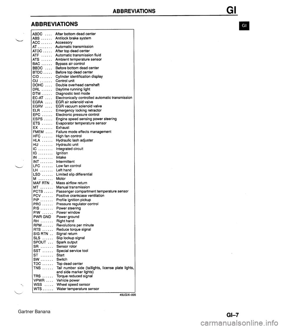
ABBREVIATIONS 4BDC .... 4BS ...... 4CC ...... 4T ........ 4TDC ..... 4TF ...... 4TS ...... 3AC ...... 3BDC .... 3TDC ..... :ID ....... 2U ....... IOHC .... IRL ...... ITM ...... IC-AT .... iGRA .... EGRV .... ELR ...... EPC ...... ESPS ..... ETS ...... EX ....... FMEM .... HFC ...... HLA ...... H U ....... IC ........ IG ........ IN ........ INT ....... LFC ...... LH ....... LSD ...... M ........ MAF RTN . MT ....... PCTS ..... PCV ...... PIP ....... PRC ...... PIS ....... PMI ...... PWR GND RH ....... RPM ...... RTS ...... SIG RTN . . SLS ...... ... SPOUT S R ....... SST ...... ST ....... SW ....... TDC ...... TNS ...... TRS ...... VPWR .... WSS ..... WTS...... After bottom dead center Antilock brake system Accessory Automatic transmission After top dead center Automatic transmission fluid Ambient temperature sensor Bypass air control Before bottom dead center Before top dead center Cylinder identification display Control unit Double overhead camshaft Daytime running light Diagnostic test mode Electronically controlled automatic transmission EGR air solenoid valve EGR vacuum solenoid valve Emergency locking retractor Electronic pressure control Engine speed sensing power steering Evaporator temperature sensor Exhaust Failure mode effects management High fan control Hydraulic lash adjuster Hydraulic unit Integrated circuit Ignition Intake Intermittent Low fan control Left hand Limited slip differential Motor Mass airflow return Manual transmission Passenger compartment temperature sensor Positive crankcase ventilation Profile ignition pickup Pressure regulator control Power steering Power window Power ground Right hand Revolutions per minute Reduce torque signal Signal return Slip lockup signal Spark output Sensor rotor Special service tool Start Switch Top dead center Tail number side (taillights, license plate lights and side marker lights) Torque reduced signal Vehicle power Wheel speed sensor Water temperature sensor Gartner Banana
Page 666 of 1708

Before beginning any service procedure. refer to section T of this manual for air bag system service warnings and audio antitheft system alarm conditions . BRAKING SYSTEM INDEX ....................................... P- 2 OUTLINE ..................................... P- 4 SPEClFlCATlONS ........................... P- 4 BRAKE SYSTEM ............................. P- 5 PREPARATION ............................. P- 5 TROUBLESHOOTING GUIDE ................ P- 6 AIR BLEEDING ............................. P- 7 BRAKE HYDRAULIC LINE ................... P- 7 BRAKE FLUID .............................. P- 8 ............................. BRAKE PEDAL P- 9 MASTER CYLINDER (STANDARD) ............ P-11 MASTER CYLINDER (ABS) .................. P-14 POWER BRAKE UNIT ....................... P-20 PROPORTIONING BYPASS VALVE ........... P-23 FRONT BRAKE (DISC) ...................... P-25 CALIPER ................................... P-28 REAR BRAKE (DISC) ........................ P-29 CALIPER ................................... P-32 PARKING BRAKE SYSTEM .................... P-34 TROUBLESHOOTING GUIDE ................ P-34 PARKING BRAKE LEVER .................... P-34 PARKING BRAKE CABLE .................... P-36 ANTILOCK BRAKE SYSTEM (ABS) ............ P-37 DESCRIPTION .............................. P-37 PREPARATION ............................. P-37 TROUBLESHOOTING GUIDE ................ P-38 CIRCUIT DIAGRAM ......................... P-52 HYDRAULIC UNIT ........................... P-53 ........................ ABS CONTROL UNIT P-55 RELAYS .................................... P-56 ABS WHEEL SPEED SENSOR (FRONT) ....... P-58 ABS SENSOR ROTOR (FRONT) .............. P-59 ABS WHEEL SPEED SENSOR (REAR) ........ P-60 ABS SENSOR ROTOR (REAR) ............... P-61 25UOPX-001 Gartner Banana
Page 668 of 1708

INDEX P ANTILOCK BRAKE SYSTEM (ABS) 1. Hydraulic unit 5. ABS sensor rotor (front) Removal / Installation ......... page P-53 Removal / Ins~ection / ................. Disassembly / Assembly ...... page P-54 Installation page P-59 2. ABS control unit 6. ABS wheel-speed sensor (rear) Removal I Installation ......... page P-55 Removal 1 Inspection I ................. 3. Relays Installation page P-60 Removal / Inspection / 7. ABS sensor rotor (rear) ......... ................. w Installation page P-56 Removal / Inspection page P-61 .................. 4. ABS wheel-speed sensor (front) Installation page P-62 Removal / Inspection / ................. Installation page P-58 Gartner Banana
Page 702 of 1708

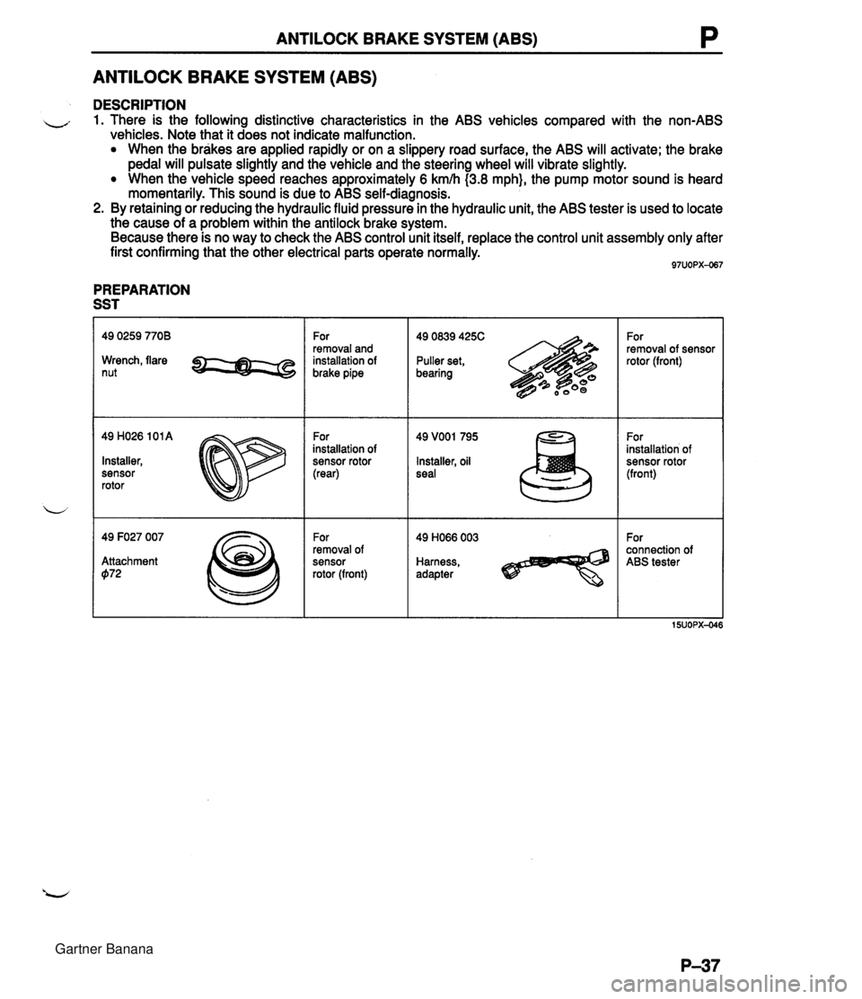
ANTILOCK BRAKE SYSTEM (ABS) P ANTILOCK BRAKE SYSTEM (ABS) DESCRIPTION - 1. There is the following distinctive characteristics in the ABS vehicles compared with the non-ABS vehicles. Note that it does not indicate malfunction. When the brakes are applied rapidly or on a slippery road surface, the ABS will activate; the brake pedal will pulsate slightly and the vehicle and the steering wheel will vibrate slightly. When the vehicle speed reaches approximately 6 kmh (3.8 mph}, the pump motor sound is heard momentarily. This sound is due to ABS self-diagnosis. 2. By retaining or reducing the hydraulic fluid pressure in the hydraulic unit, the ABS tester is used to locate the cause of a problem within the antilock brake system. Because there is no way to check the ABS control unit itself, replace the control unit assembly only after first confirming that the other electrical parts operate normally. PREPARATION SST Wrench, flare nut 49 H026 101 A Installer, sensor rotor 49 F027 007 Attachment 072 For removal and installation of brake pipe For installation of sensor rotor (rear) For removal of sensor rotor (front) 49 0839 425C Puller set, bearing Installer, oil seal Harness, adapter For removal of sensor rotor (front) For installation of sensor rotor (front) For connection of ABS tester Gartner Banana
Page 716 of 1708

ANTILOCK BRAKE SYSTEM (ABS) P ABS CONTROL UNIT 35-PIN CONNECTOR OHMMETER 15UOPX-OI Check rotor Check the rotor for missing or damaged teeth and replace as necessary. Check alternator Refer to section G. Check wheel-speed sensor Caution To prevent damage to the terminals, create a probe by wrapping a thin wire around the tester lead before inserting. 1. Using an ohmmeter, check for continuity at the control unit connector terminals. 0----0: Indicates continuity Right front Left rear Right rear 2. If the continuity is not as specified, check the wiring har- ness (Wheel-speed sensor - Control unit). 3. If the continuity is OK, check voltage between 1K and 1 G, 10 and 1 Q, 1 U and 1 F, and 1 L and 1 P while rotating the wheel one rotation per second by hand. 4. If voltage is not approximately 50 mV--60 mV, the wheel-speed sensor is faulty. 5. If voltage is approximately 50 mV-60 mV, the control unit is faulty. 1L Check hydraulics Verify that all brake fluid connections are tight and that no fluid is leaking. IP 1Q Left front 0--0 Check hydraulic unit wiring 1. Verify that the hydraulic unit connectors are properly secured. 2. Verify that the valve relay and motor relay are properly secured. IG 1K 0-4 1U 10 S-0 IF 0-4 Gartner Banana
Page 724 of 1708

ANTILOCK BRAKE SYSTEM (ABS) P ABS SENSOR ROTOR (FRONT) Removal l Inspection / lnstallation 1. Inspect the ABS sensor rotor for missing and damaged teeth. Note The sensor rotor does not need to be removed unless you are replacing it. 2. Remove in the order shown in the figure, referring to Removal Note. 3. Install in the reverse order of removal, referring to lnstallation Note. 25UOPX-03 1. Wheel hub 2. ABS sensor rotor .......... Removal / Installation section M Removal Note ................... below Installation Note ................. below Removal note ABS sensor rotor Remove the sensor rotor from the wheel hub with the SST. lnstallation note ABS sensor rotor Press a new sensor rotor onto the wheel hub with the SST. Gartner Banana
Page 726 of 1708

ANTILOCK BRAKE SYSTEM (ABS) P ABS SENSOR ROTOR (REAR) Removal / Inspection 1. Inspect the ABS sensor rotor for missing and damaged teeth. Note The sensor rotor does not need to be removed unless you are replacing it. 2. Remove in the order shown in the figure, referring to Removal Note. 25uopx-o: 1. Drive shaft 2. Sensor rotor Removal . :. . . . . . . . . . . . . . . . . . . section M Removal Note . . . . . . . . . . . . . . . . . . . below 3. Boot band and boot Removal note Sensor rotor Tap the sensor rotor off the drive shaft with a chisel. Gartner Banana
Page 727 of 1708

P ANTILOCK BRAKE SYSTEM (ABS) -.A 1. Sensor rotor 3. Drive shaft ................... ................. Installation Note below Installation section M 2. Boot and boot band ................... Installation section M lnstallation note ABS sensor rotor Set a new sensor rotor on the drive shaft and press it on with the SST. Gartner Banana
Page 1132 of 1708

SPECIAL TOOLS ST STEERING SYSTEM (CON' r TOOL NUMBER & DESCRIPTION PRIORITY ILLUSTRATION TOOL NUMBER & DESCRIPTION PRIORITY ILLUSTRATION Handle Remover, oil seal & bearing 49 DO32 303 Attachment 49 01 18 850C Puller, ball joint 49 H032 301 Wrench Attachment, preload measuring BRAKING SYSTEM TOOL NUMBER & DESCRIPTION PRIORITY ILLUSTRATION ILLUSTRATION Expand tool, disc brake 49 F043 001 Adjust gauge Wrench, socket A 49 0208 701 A Air out tool, boot Lock tool, turning A 49 8043 001 Adjust gauge 49 U043 OAO A Gauge set, oil wessure Installer, sensor rotor A Gartner Banana