height adjustment MAZDA MX-5 1994 Workshop Manual
[x] Cancel search | Manufacturer: MAZDA, Model Year: 1994, Model line: MX-5, Model: MAZDA MX-5 1994Pages: 1708, PDF Size: 82.34 MB
Page 340 of 1708

CLUTCHPEDAL H Minimum disengagement height: 68mm (2.68 in) (With carpet) CLUTCHPEDAL ADJUSTMENT Height lnspection 1. Measure the distance from the upper surface of the ped- al pad to the carpet. Pedal height: 175--185mm (6.89-7.28 in) (With carpet) 2. If necessary, adjust the height. Adjustment 1. Disconnect the clutch switch connector. 2. Loosen locknut @ and turn clutch switch @I until the height is correct. I 3. Tighten locknut @. Tightening torque: l3.Cl7.6 N-m (1 4Gl8O kgf-cm, 122-1 56 in-IM) 4. After adjustment, inspect the free play. Free Play lnspection 1. Depress the clutch pedal by hand until clutch resistance is felt. Free play: 0.6-3.lmm (0.02-0.12 in) Total free play: S13mm (0.20-0.51 in) 2. If necessary, adjust the free play. Adjustment 1. Loosen locknut 0 and turn push rod 03 until free play is correct. 2. Verify that the disengagement height as measured from the upper surface of the pedal pad to the carpet is correct when the pedal is fully depressed. 3. Tighten locknut 0. Tightening torque: 11 .&l6.6 N.m (120-1 70 kgtcm, 105--147 in.lbf} 4. After adjustment, inspect the height. Gartner Banana
Page 608 of 1708
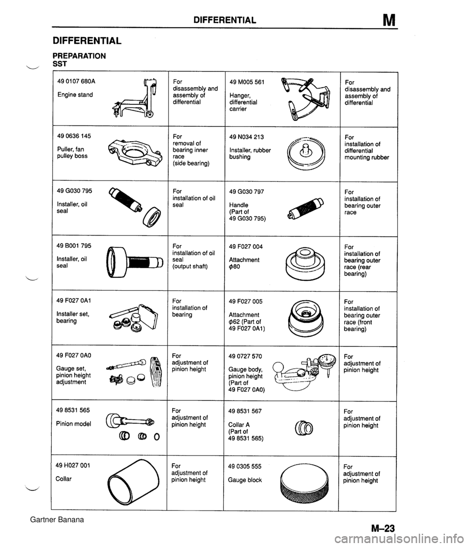
DIFFERENTIAL M DIFFERENTIAL PREPARATION u SST 49 01 07 680A Engine stand For disassembly and assembly of differential 49 MOO5 561 Hanger, differential carrier For disassembly and assembly of differential For removal of bearing inner race (side bearing) 49 NO34 21 3 Installer, rubber bushing For installation of differential mounting rubber - --.. - Puller, fan pulley boss 49 GO30 795 Installer, oil seal For installation of oil seal For installation of bearing outer race Handle (Part of 49 GO30 795) 49 BOO1 795 Installer, oil seal For installation of oil seal (output shaft) 49 F027 004 Attachment $80 For installation of bearing outer race (rear bearing) 49 F027 OAl For installation of bearing 49 F027 005 Attachment $I62 (Part of 49 F027 OAl ) For installation of bearing outer race (front bearing) Installer set, bearing 49 F027 OAO Gauge set, pinion height adjustment 49 0727 570 Gauge body, pinion height (Part of For adjustment of pinion height For adjustment of pinion height 49 F027 OAO) For adjustment of pinion height For adjustment of oinion height Pinion model @==@ Collar A (Part of 49 8531 565) For adjustment of oinion height adjustment of )inion height Gauge block Gartner Banana
Page 626 of 1708
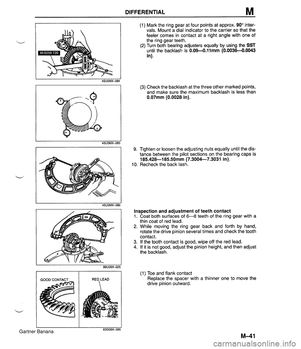
DIFFERENTIAL M (1) Mark the ring gear at four points at approx. 90" inter- vals. Mount a dial indicator to the carrier so that the feeler comes in contact at a right angle with one of the ring gear teeth. (2) Turn both bearing adjusters equally by using the SST until the backlash is 0.09-0.11mm {0.0036-€).0043 in). (3) Check the backlash at the three other marked points, and make sure the maximum backlash is less than 0.07mm (0.0028 in). 9. Tighten or loosen the adjusting nuts equally until the dis- tance between the pilot sections on the bearing caps is 185.428-1 85SOmm (7.3004--7.3031 in). 10. Recheck the back lash. Inspection and adjustment of teeth contact 1. Coat both surfaces of 6-8 teeth of the ring gear with a thin coat of red lead. 2. While moving the ring gear back and forth by hand, rotate the drive pinion several times and check the tooth contact. 3. If the tooth contact is good, wipe off the red lead. 4. If it is not good, adjust the pinion height, and then adjust the backlash. (1) Toe and flank contact Replace the spacer with a thinner one to move the drive pinion outward. Gartner Banana
Page 674 of 1708
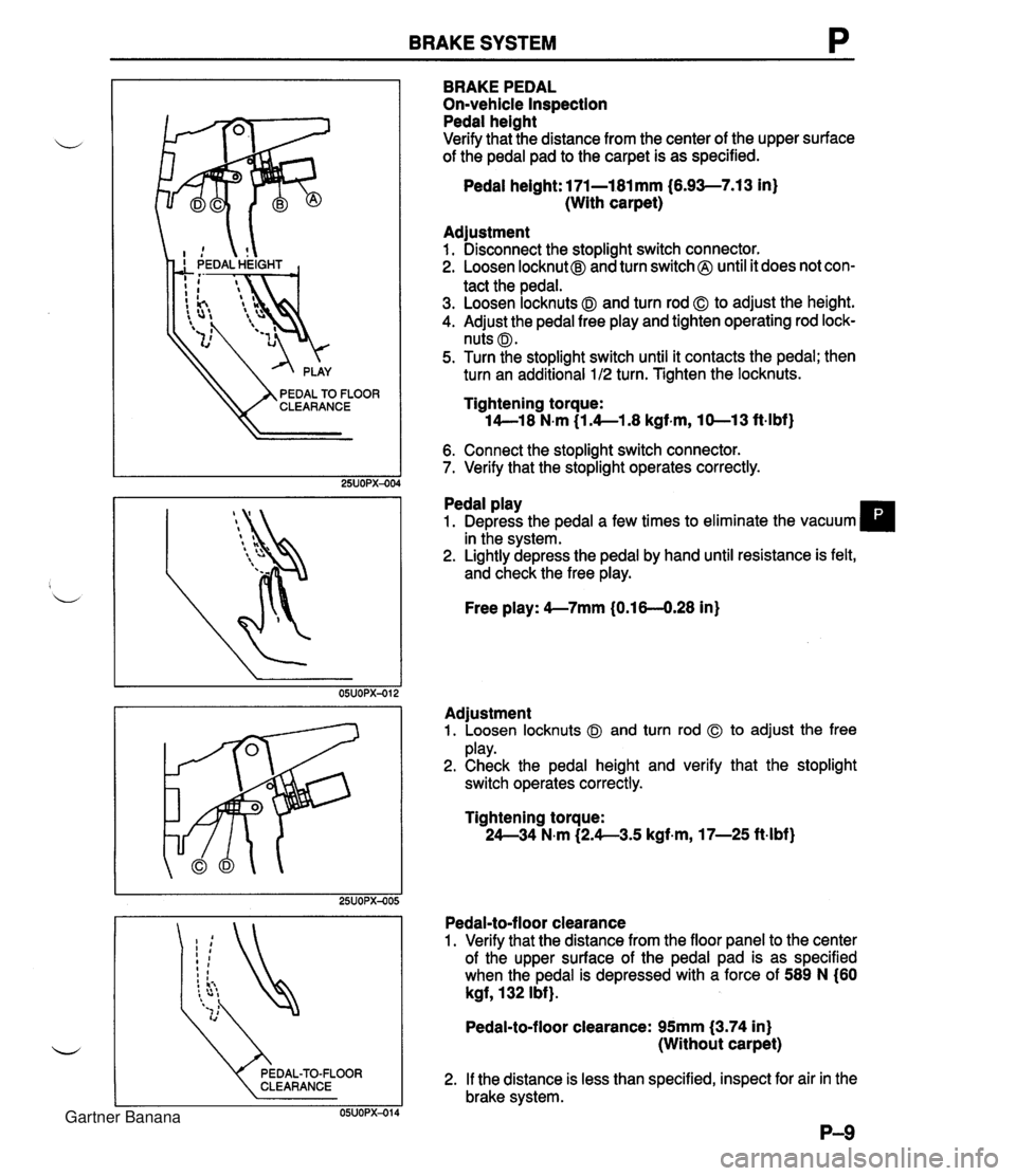
BRAKE SYSTEM P CLEARANCE BRAKE PEDAL On-vehicle Inspection Pedal height Verify that the distance from the center of the upper surface of the pedal pad to the carpet is as specified. Pedal height: l7l-l8l mm (6.93-7.13 in} (With carpet) Adjustment 1. Disconnect the stoplight switch connector. 2. Loosen locknut@ and turn switch @ until it does not con- tact the pedal. 3. Loosen locknuts @I and turn rod 0 to adjust the height. 4. Adjust the pedal free play and tighten operating rod lock- nuts @I. 5. Turn the stoplight switch until it contacts the pedal; then turn an additional 1 /2 turn. Tighten the locknuts. Tightening torque: 14--18 N.m (1.4--1.8 kgf-m, 10-13 ft-lbf) 6. Connect the stoplight switch connector. 7. Verify that the stoplight operates correctly. Pedal play 1. Depress the pedal a few times to eliminate the vacuum in the system. 2. Lightly depress the pedal by hand until resistance is felt, and check the free play. Free play: 4--7mm (0.16-4.28 in) Adjustment 1. Loosen locknuts @I and turn rod to adjust the free play. 2. Check the pedal height and verify that the stoplight switch operates correctly. Tightening torque: 24--34 N.m (2.4--3.5 kgf-m, 17-25 ft-lbf} Pedal-to-floor clearance 1. Verify that the distance from the floor panel to the center of the upper surface of the pedal pad is as specified when the pedal is depressed with a force of 589 N (60 kgf, 132 Ibf}. Pedal-to-floor clearance: 95mm (3.74 in} (Without carpet) 2. If the distance is less than specified, inspect for air in the brake system. Gartner Banana
Page 681 of 1708
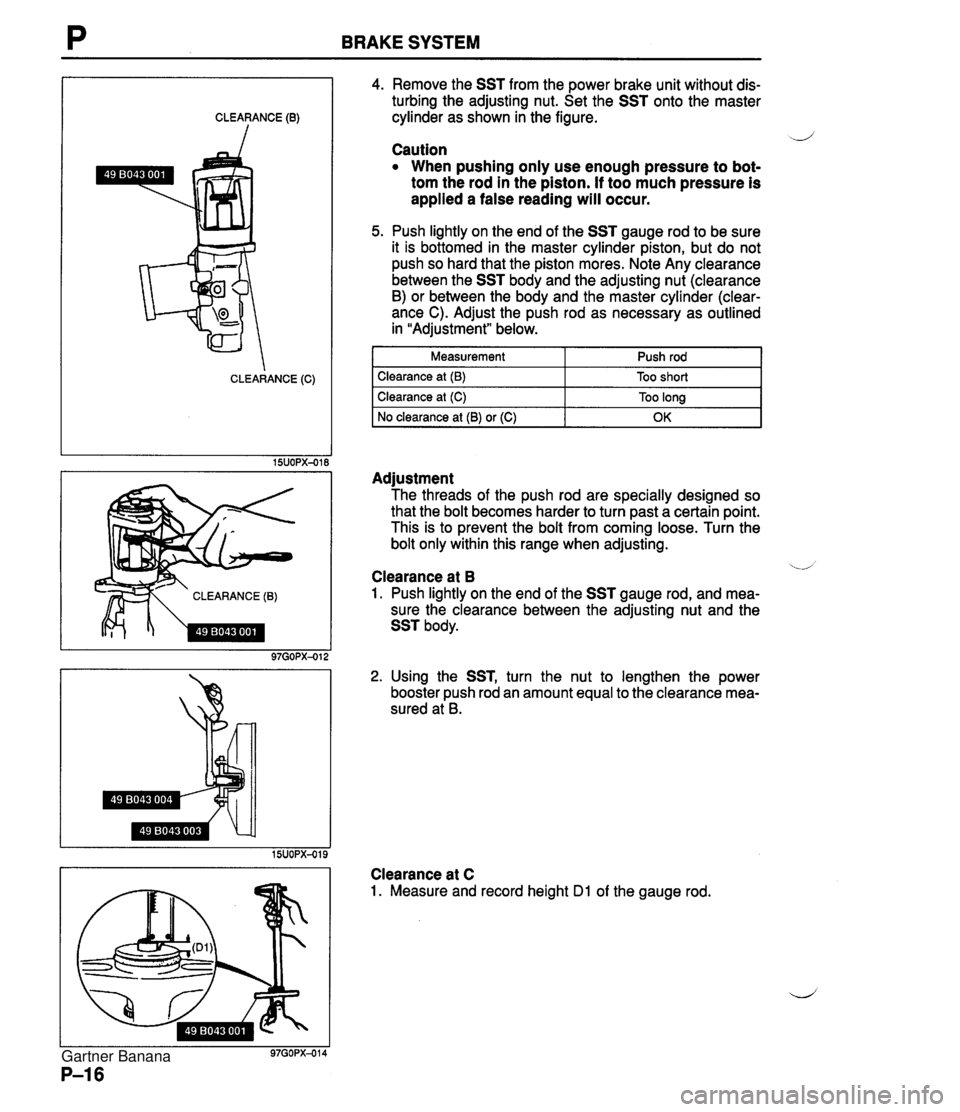
BRAKE SYSTEM CLEARANCE (0) CLEARANCE (C) CLEARANCE (B) 4. Remove the SST from the power brake unit without dis- turbing the adjusting nut. Set the SST onto the master cylinder as shown in the figure. -J Caution When pushing only use enough pressure to bot- tom the rod in the piston. If too much pressure is applied a false reading will occur. 5. Push lightly on the end of the SST gauge rod to be sure it is bottomed in the master cylinder piston, but do not push so hard that the piston mores. Note Any clearance between the SST body and the adjusting nut (clearance B) or between the body and the master cylinder (clear- ance C). Adjust the push rod as necessary as outlined in "Adjustment" below. I Measurement 1 Push rod I I Clearance at (B) I Too short I Adjustment The threads of the push rod are specially designed so that the bolt becomes harder to turn past a certain point. This is to prevent the bolt from coming loose. Turn the bolt only within this range when adjusting. Clearance at (C) No clearance at (B) or (C) '.A Clearance at B 1. Push lightly on the end of the SST gauge rod, and mea- sure the clearance between the adjusting nut and the SST body. Too long OK 2. Using the SST, turn the nut to lengthen the power booster push rod an amount equal to the clearance mea- sured at B. Clearance at C 1. Measure and record height Dl of the gauge rod. Gartner Banana
Page 738 of 1708
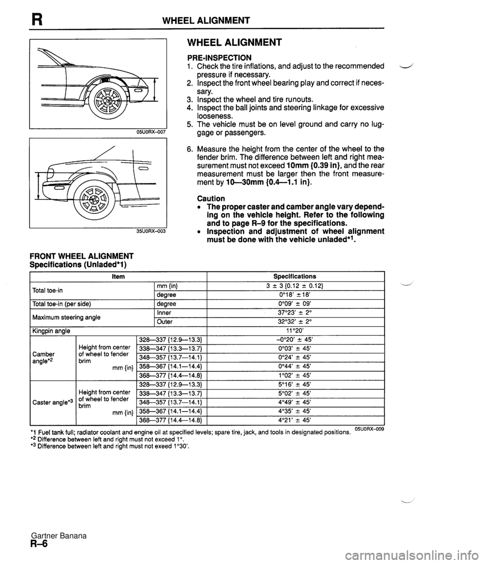
WHEEL ALIGNMENT WHEEL ALIGNMENT FRONT WHEEL ALIGNMENT Specifications (Unladed*l) PRE-INSPECTION 1. Check the tire inflations, and adjust to the recommended d pressure if necessary. 2. lnspect the front wheel bearing play and correct if neces- sary. 3. lnspect the wheel and tire runouts. 4. Inspect the ball joints and steering linkage for excessive looseness. 5. The vehicle must be on level ground and carry no lug- gage or passengers. 6. Measure the height from the center of the wheel to the fender brim. The difference between left and right mea- surement must not exceed 10mm (0.39 in), and the rear measurement must be larger then the front measure- ment by 10-30mm (0.4--1.1 in). Caution The proper caster and camber angle vary depend- ing on the vehicle height. Refer to the following and to page R-9 for the specifications. Inspection and adjustment of wheel alignment must be done with the vehicle unladed*'. . . I Y -- t~otal toe-in l~er side) I 1 dearee 0'09' + 09' I Total toe-in 3 2 3 I0.12 2 0.12) 0'1 8' 2 18' mm (in) dearee Maximum steering angle U - Inner Outer 11 '20' -0°20' 2 45' 0'03' ? 45' 0'24' 2 45' 0°44' -+ 45' 1'02' -+ 45' 5'1 6' ? 45' 5O02' -+ 45' 4O49' 2 45' 4'35' -+ 45' 4'21 ' -+ 45' I Kingpin angle 37"23' -+ 2" 32O32' 2 2" '1 Fuel tank full; radiator coolant and engine oil at specified levels; spare tire, jack, and tools in designated positions. OSUORX-009 ** Difference between left and right must not exceed lo. '3 Difference between left and right must not exeed 1'30'. 328-337 {I 2.9-1 3.3) 338-347 {I 3.3-1 3.7) 340-357 I13.7-14.1) 358-367 {I 4.1-14.4) 36&377 {I 4.4--14.8) 328-337 {I 2.9--13.3) 338-347 {I 3.3-1 3.7) 348-357 113.7-14.1) 358-367 {I 4.1-14.4) 368-377 {I 4.4--14.8) Camber angleg2 Caster angle*3 Height from center Of wheel to fender brim mm {in) Height from center Of wheel to fender brim mm (in) Gartner Banana
Page 800 of 1708

s WINDSHIELD WIPER AND WASHER I mm (in) 05UOSX459 I MOLDING EDGE ' C~NTER mm (in) 05UOSx-060 CONNECTOR SHAFT Adjustment Arm height Set the arm height as shown. Washer nozzle Insert a needle or similar object into the nozzle hole and move the nozzle to adjust the spray direction. Installation Note Wiper arm and blade Clean the wiper arm connector shafts with a wire brush before installing the wiper warms. Gartner Banana
Page 836 of 1708

CONVERTIBLE TOP 26. Install the retainers to the link assembly, aligning the retainer marks with the retainer mounting screws. 27. Install the weatherstri~s to the link assemblv. 28. Install the convertible'to~ to the bodv. (~ef& to paae S-67.) PROTECTOR ADJUSTING NUT WINDSHIELD HEADER CONVERTIBLE TOP I Adjustment Top latch assembly 1. Lift the protector away from the top latch assembly ad- justing nut. 2. Turn the adjusting nut clockwise to decrease clearance A and height B; turn the nut counterclockwise to increase them. 3. Secure the adjusting nut with the protector. Gartner Banana
Page 840 of 1708

DETACHABLE HARDTOP PROTECTOR ADJUSTING NUT DETACHABLE HARDTOl WINDSHIELD HEADER I @ 1 5 r 2 (0.2 f 0.08) @ 1 0 r 2 (0 * 0.08) mm (in) 45UOSX-11 f Adjustment Top latch assembly 1. Lift the protector away from the top latch assembly ad- justing nut. d 2. Turn the adjusting nut clockwise to decrease clearance A and height B; turn the nut counterclockwise to increase them. 3. Secure the adjusting nut with the protector. I I Side latch assembly 1. Lift the protector away from the side latch assembly ad- justing nut. 2. Turn the adjusting nut clockwise to tighten the striker and side latch assembly engagement; turn the nut counter- clockwise to loosen the engagement. - 3. Secure the adjusting nut with the protector. ADJUSTING NUT 45UOSX-117 Rear deck latch assembly 1. Remove the screw and open the latch cover. 2. Loosen the plate mounting bolts. 3. Install the detachable hardtop to the body. 4. Move the plate right, left, fore, or aft until it is tight. 5. Tighten the plate mounting bolts. Tightening torque: 18-26 N.m (1.8-2.7 kgfsm, 14--19 ft-lbf) 6. Close the latch cover and install the screw. Gartner Banana
Page 901 of 1708

T LIGHTING SYSTEM Stoplight Switch Adjustment 1. Adjust the brake pedal height. (Refer to section P.) 2. Disconnect the stoplight switch connector. 4 3. Loosen the stoplight switch locknut. 4. Turn the stoplight switch until it contacts the pedal arm. Turn an additional 112 turn. 5. Tighten the locknut. Locknut tightening torque: 14-18 N.m (1.4-1.8 kgf-m, 120-156 in-lbf) I I I Brake pedal depress I 0 0 1 I Inspection Stoplight switch 1. Disconnect the stoplight switch connector. 2. Check for continuity between terminals of the switch. lnspection condition 3. If not as specified, replace the stoplight switch. Terminal A I B I Brake pedal released I m : Continuity Gartner Banana