tow MAZDA MX-5 1994 Workshop Manual
[x] Cancel search | Manufacturer: MAZDA, Model Year: 1994, Model line: MX-5, Model: MAZDA MX-5 1994Pages: 1708, PDF Size: 82.34 MB
Page 3 of 1708
GENERAL INFORMATION SAFETY INFORMATION ...................... GI- 2 LUBRICANTS .............................. GI- 2 JACKING POSITIONS ...................... GI- 2 SAFETY STAND POSITIONS ................ GI- 2 VEHICLE LIFT POSITIONS .................. GI- 3 DYNAMOMETER ........................... GI- 3 COMPRESSED AIR ........................ GI- 3 HOW TO USE THIS MANUAL ................. GI- 4 ADVISORY MESSAGES .................... GI- 4 PREPARATION ............................ GI- 4 REPAIR PROCEDURE ...................... GI- 4 SYMBOLS ................................. GI- 5 IDENTIFICATION NUMBER LOCATIONS ....... GI- 6 UNITS ...................................... GI- 6 ABBREVIATIONS ............................ GI- 7 SAE STANDARDS ........................... GI- 8 FUNDAMENTAL PROCEDURES ............... GI-11 PROTECTION OF THE VEHICLE ............ GI-11 PREPARATION OF TOOLS AND MEASURING EQUIPMENT ............................. GI-11 SPECIAL TOOLS ........................... GI-11 REMOVALOF PARTS ...................... GI-11 DISASSEMBLY ............................ GI-11 REASSEMBLY ............................. GI-1 2 ADJUSTMENTS ............................ GI-13 RUBBER PARTS AND TUBING .............. GI-13 HOSE CLAMPS ............................ GC13 TORQUE FORMULAS ...................... GI-13 VISE ...................................... GI-13 ELECTRICAL TROUBLESHOOTING TOOLS ... GI-14 TEST LIGHT ............................... GI-14 JUMPER WIRE ............................ GC14 VOLTMETER .............................. GI-14 OHMMETER ............................... GI-14 ELECTRICAL PARTS ......................... GI-1 4 BATTERY ................................. GI-1 4 BATTERY CABLE .......................... GI-1 5 CONNECTORS ............................ GI-15 TERMINALS ............................... GI-16 SENSORS. SWITCHES. AND RELAYS ....... GI-17 WIRING HARNESS ......................... GI-17 FUSE ..................................... GI-17 INSTALLATION OF MOBILE TWO-WAY RADIO SYSTEM ................................... GI-18 AUDIO ANTITHEFT SYSTEM ................. GI-18 TOWING .................................... GI-19 45UGIX-001 Gartner Banana
Page 21 of 1708
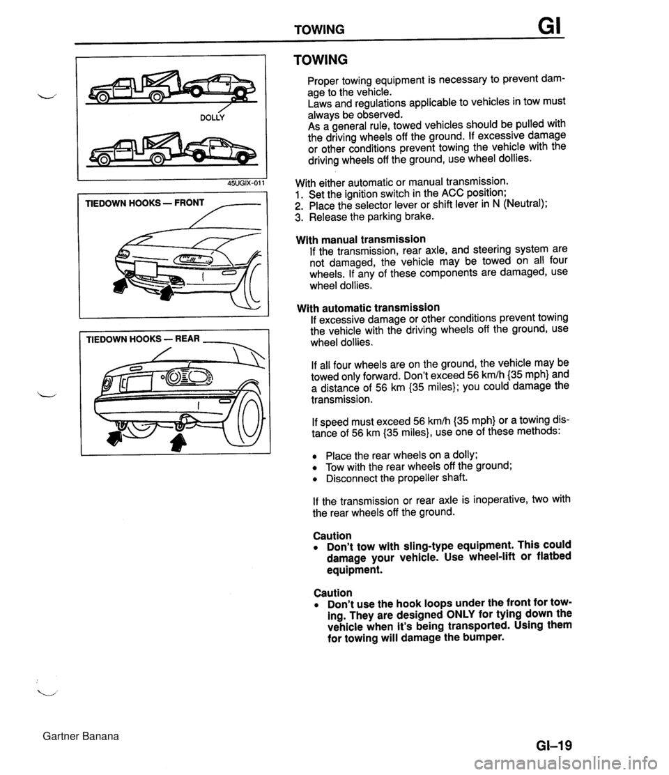
TOWING TIEDOWN HOOKS - FRONT /-- TIEDOWN HOOKS - REAR - TOWING Proper towing equipment is necessary to prevent dam- age to the vehicle. Laws and regulations applicable to vehicles in tow must always be observed. As a general rule, towed vehicles should be pulled with the driving wheels off the ground. If excessive damage or other conditions prevent towing the vehicle with the driving wheels off the ground, use wheel dollies. With either automatic or manual transmission. 1. Set the ignition switch in the ACC position; 2. Place the selector lever or shift lever in N (Neutral); 3. Release the parking brake. With manual transmission If the transmission, rear axle, and steering system are not damaged, the vehicle may be towed on all four wheels. If any of these components are damaged, use wheel dollies. With automatic transmission If excessive damage or other conditions prevent towing the vehicle with the driving wheels off the ground, use wheel dollies. If all four wheels are on the ground, the vehicle may be towed only forward. Don't exceed 56 kmlh {35 mph} and a distance of 56 km (35 miles); you could damage the transmission. If speed must exceed 56 kmlh (35 mph} or a towing dis- tance of 56 km (35 miles}, use one of these methods: Place the rear wheels on a dolly; Tow with the rear wheels off the ground; Disconnect the propeller shaft. If the transmission or rear axle is inoperative, two with the rear wheels off the ground. Caution Don't tow with sling-type equipment. This could damage your vehicle. Use wheel-lift or flatbed equipment. Caution Don't use the hook loops under the front for tow- ing. They are designed ONLY for tying down the vehicle when it's being transported. Using them for towing will damage the bumper. GI-I 9 Gartner Banana
Page 103 of 1708
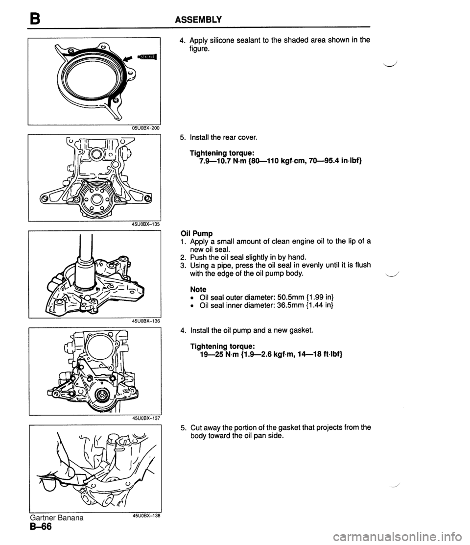
ASSEMBLY 4. Apply silicone sealant to the shaded area shown in the figure. 5. Install the rear cover Tightening torque: 7.9-1 0.7 N.m (80-1 10 kgfem, 70-95.4 in-lbf) Oil Pump 1. Apply a small amount of clean engine oil to the lip of a new oil seal. 2. Push the oil seal slightly in by hand. 3. Using a pipe, press the oil seal in evenly until it is flush with the edge of the oil pump body. U' Note Oil seal outer diameter: 50.5mm (1.99 in} Oil seal inner diameter: 36.5mm (1.44 in) 4. Install the oil pump and a new gasket. Tightening torque: 19-25 N.m (1 -9-2.6 kgf-m, 14--18 ft-lbf) 5. Cut away the portion of the gasket that projects from the body toward the oil pan side. Gartner Banana
Page 107 of 1708
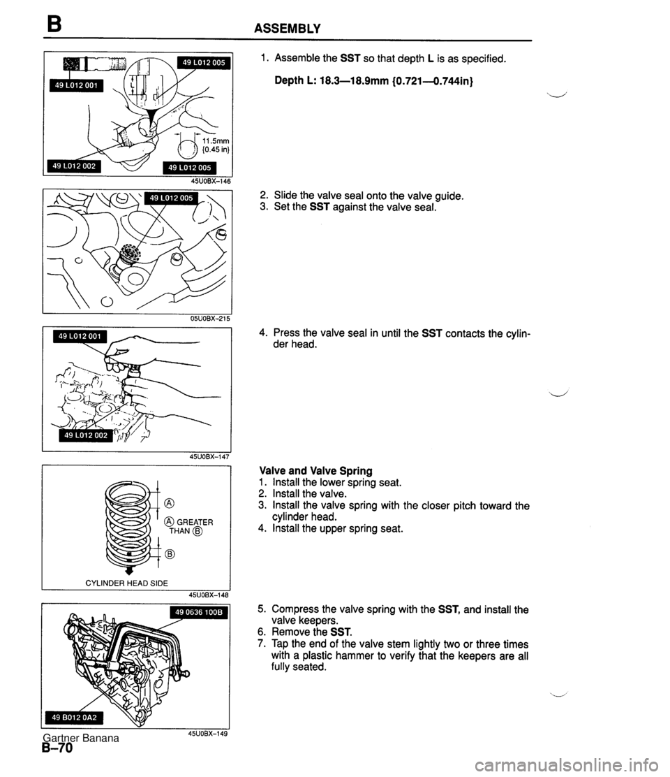
B ASSEMBLY @ @ GREATER THAN @ @ 1. Assemble the SST so that depth L is as specified. Depth L: 18.3-18.9mm (0.721-0.744in) 2. Slide the valve seal onto the valve guide. 3. Set the SST against the valve seal. 4. Press the valve seal in until the SST contacts the cylin- der head. Valve and Valve Spring 1. lnstall the lower spring seat. 2. Install the valve. 3. lnstall the valve spring with the closer pitch toward the cylinder head. 4. lnstall the upper spring seat. 5. Compress the valve spring with the SST, and install the valve keepers. 6. Remove the SST. 7. Tap the end of the valve stem lightly two or three times with a plastic hammer to verify that the keepers are all fully seated. Gartner Banana
Page 145 of 1708
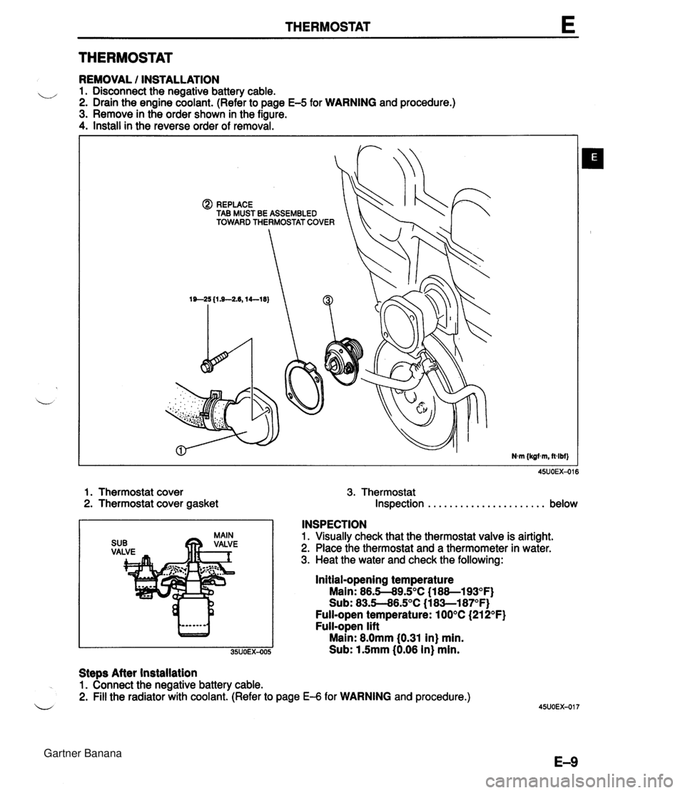
THERMOSTAT E THERMOSTAT REMOVAL / INSTALLATION u 1. Disconnect the negative battery cable. 2. Drain the engine coolant. (Refer to page E-5 for WARNING and procedure.) 3. Remove in the order shown in the figure. 4. Install in the reverse order of removal. @) REPLACE TAB MUST BE ASSEMBLED TOWARD THERMOSTAT COVER 1. Thermostat cover 3. Thermostat 2. Thermostat cover gasket Inspection . . . . . . . . . . . . . . . . . . . . . . below INSPECTION 1. Visually check that the thermostat valve is airtight. 2. Place the thermostat and a thermometer in water. 3. Heat the water and check the following: Initial-opening temperature Main: 86.5-89.S°C (1 88--193OF) Sub: 83.5--86.S°C (1 8Sl87OF) Full-open temperature: 100°C (21 2°F) Full-open lift Main: 8.0mm 10.31 in) min. Sub: 1.5mm (0.06 in) min. Steps After installation 1. Connect the negative battery cable. 2. Fill the radiator with coolant. (Refer to page €4 for WARNING and procedure.) u Gartner Banana
Page 390 of 1708
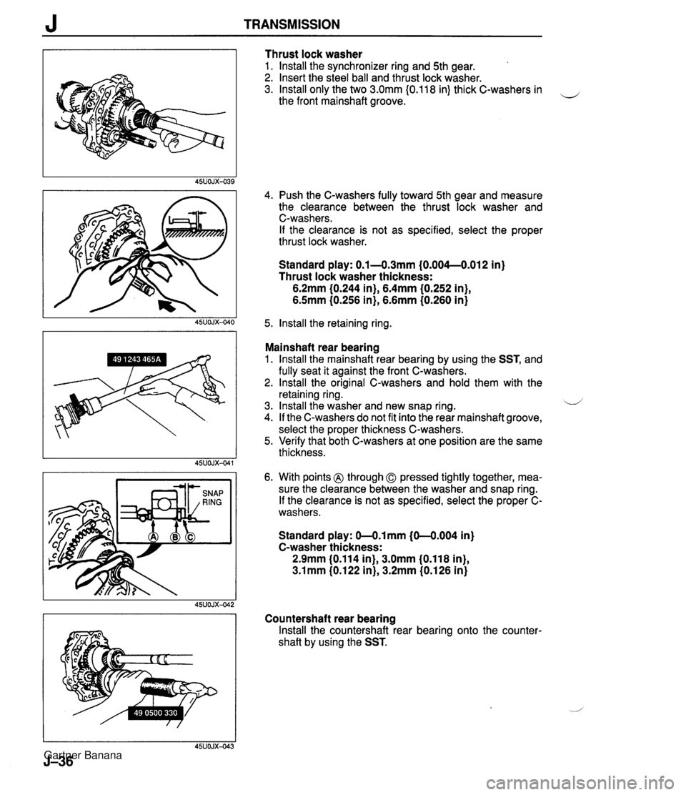
J TRANSMISSION Thrust lock washer 1. lnstall the synchronizer ring and 5th gear. 2. Insert the steel ball and thrust lock washer. 3. lnstall only the two 3.0mm I0.118 in) thick C-washers in the front mainshaft groove. 4. Push the C-washers fully toward 5th gear and measure the clearance between the thrust lock washer and C-washers. If the clearance is not as specified, select the proper thrust lock washer. Standard play: 0.1 -4.3mm {O.OO4--O.Ol2 in) Thrust lock washer thickness: 6.2mm (0.244 in), 6.4mm (0.252 in}, 6.5mm (0.256 in), 6.6mm (0.260 in} 5. lnstall the retaining ring. Mainshaft rear bearing 1. lnstall the rnainshaft rear bearing by using the SST, and fully seat it against the front C-washers. 2. lnstall the original C-washers and hold them with the retaining ring. 3. lnstall the washer and new snap ring. u 4. If the C-washers do not fit into the rear mainshaft groove, select the proper thickness C-washers. 5. Verify that both C-washers at one position are the same thickness. 6. With points @ through 0 pressed tightly together, mea- sure the clearance between the washer and snap ring. If the clearance is not as specified, select the proper C- washers. Standard play: 0-0.lmm (0-4.004 in) C-washer thickness: 2.9mm (0.114 in), 3.0mm (0,118 in), 3.1 mm (0.1 22 in), 3.2mm (0.1 26 in) Countershaft rear bearing lnstall the countershaft rear bearing onto the counter- shaft by using the SST. Gartner Banana
Page 466 of 1708
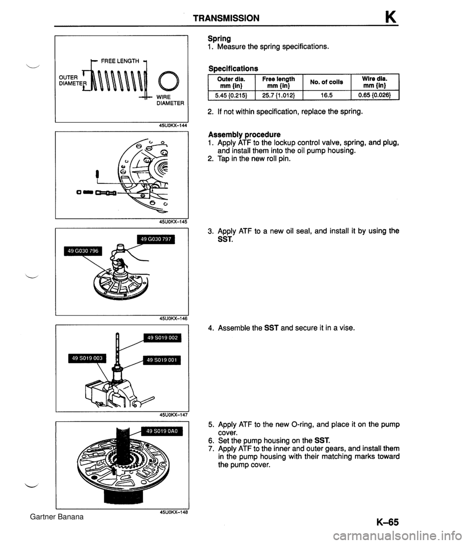
TRANSMISSION K WIRE DIAMETER Spring 1. Measure the spring specifications. Soecifications I Outer dia. I Free Ienpth I cO1ls I :Ired$ mm {in) mm {in) I 2. If not within specification, replace the spring. Assembly procedure 1. Apply ATF to the lockup control valve, spring, and plug, and install them into the oil pump housing. 2. Tap in the new roll pin. 3. Apply ATF to a new oil seal, and install it by using the SST. 4. Assemble the SST and secure it in a vise. 5. Apply ATF to the new O-ring, and place it on the pump cover. 6. Set the pump housing on the SST. 7. Apply ATF to the inner and outer gears, and install them in the pump housing with their matching marks toward the pump cover. Gartner Banana
Page 471 of 1708
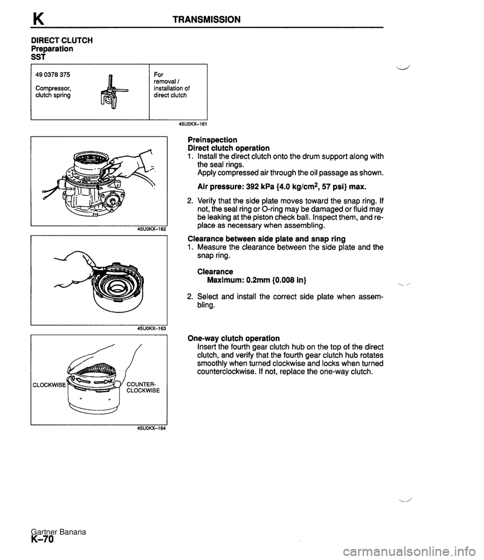
K TRANSMISSION DIRECT CLUTCH Preparation SST CLOCKWISE 49 0378 375 Compressor, clutch spring Preinspection Direct clutch operation 1. Install the direct clutch onto the drum support along with the seal rings. Apply compressed air through the oil passage as shown. For removal 1 installation of direct clutch Air pressure: 392 kPa (4.0 kgtcm*, 57 psi) max. 2. Verify that the side plate moves toward the snap ring. If not, the seal ring or O-ring may be damaged or fluid may be leaking at the piston check ball. Inspect them, and re- place as necessary when assembling. Clearance between side plate and snap ring 1. Measure the clearance between the side plate and the snap ring. Clearance Maximum: 0.2mm (0.008 in) i -, 2. Select and install the correct side plate when assern- bling. One-way clutch operation Insert the fourth gear clutch hub on the top of the direct clutch, and verify that the fourth gear clutch hub rotates smoothly when turned clockwise and locks when turned counterclockwise. If not, replace the one-way clutch. Gartner Banana
Page 475 of 1708
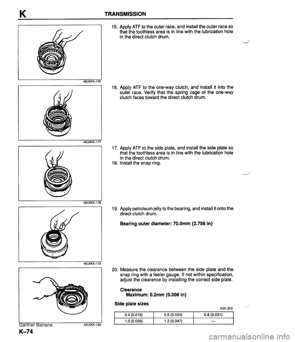
TRANSMISSION 15. Apply ATF to the outer race, and install the outer race so that the toothless area is in line with the lubrication hole in the direct clutch drum. d 16. Apply ATF to the one-way clutch, and install it into the outer race. Verify that the spring cage of the one-way clutch faces toward the direct clutch drum. 17. Apply ATF to the side plate, and install the side plate so that the toothless area is in line with the lubrication hole in the direct clutch drum. 18. Install the snap ring. 19. Apply petroleum jelly to the bearing, and install it onto the direct clutch drum. Bearing outer diameter: 70.0mm (2.756 in) 20. Measure the clearance between the side plate and the snap ring with a feeler gauge. If not within specification, adjust the clearance by installing the correct side plate. Clearance Maximum: 0.2mm (0.008 in) Side plate sizes mm {in) - Gartner Banana
Page 487 of 1708
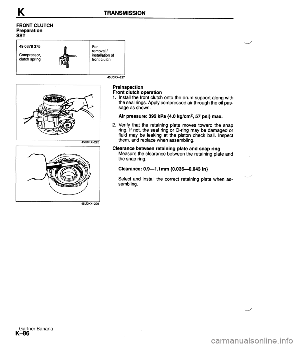
K TRANSMISSION FRONT CLUTCH Preparation SST Preinspection Front clutch operation 1. Install the front clutch onto the drum support along with the seal rings. Apply compressed air through the oil pas- sage as shown. 49 0378 375 Compressor, clutch spring Air pressure: 392 kPa (4.0 kglcm*, 57 psi} max. For removal / installation of front clutch 2. Verify that the retaining plate moves toward the snap ring. If not, the seal ring or O-ring may be damaged or fluid may be leaking at the piston check ball. Inspect them, and replace when assembling. Clearance between retaining plate and snap ring Measure the clearance between the retaining plate and the snap ring. Clearance: 0.9--1 .l mm (0.036-0.043 in} .--- Select and install the correct retaining plate when as- sembling. Gartner Banana