inflation pressure MAZDA MX-5 1994 Workshop Manual
[x] Cancel search | Manufacturer: MAZDA, Model Year: 1994, Model line: MX-5, Model: MAZDA MX-5 1994Pages: 1708, PDF Size: 82.34 MB
Page 731 of 1708

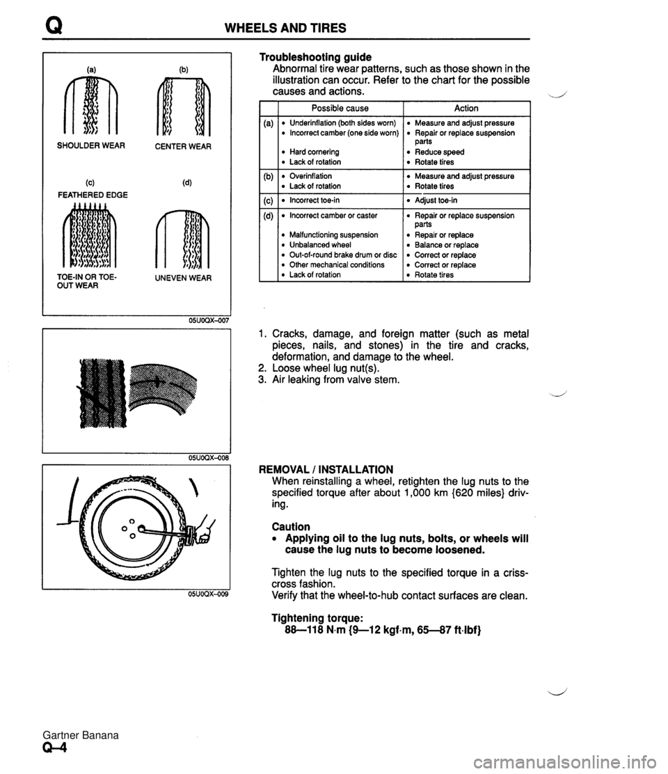
WHEELS AND TIRES SHOULDER WEAR CENTER WEAR (c) (4 FEATHERED EDGE TOE-IN OR TOE- UNEVEN WEAR OUT WEAR Troubleshooting guide Abnormal tire wear patterns, such as those shown in the illustration can occur. Refer to the chart for the possible causes and actions. d' Possible cause I Action I I Underinflation (both sides worn) I Measure and adjust pressure Overinflation Measure and adjust pressure Lack of rotation Rotate tires I Incorrect camber (one side worn) Hard cornering Lack of rotation Incorrect toe-in I Adjust toe-in I Repair or replace suspension parts Reduce speed Rotate tires 1. Cracks, damage, and foreign matter (such as metal pieces, nails, and stones) in the tire and cracks, deformation, and damage to the wheel. 2. Loose wheel lug nut(s). 3. Air leaking from valve stem. Incorrect camber or caster Malfunctioning suspension Unbalanced wheel Out-of-round brake drum or disc Other mechanical conditions Lack of rotation REMOVAL / INSTALLATION When reinstalling a wheel, retighten the lug nuts to the specified torque after about 1,000 km (620 miles} driv- ing. Repair or replace suspension parts Repair or replace Balance or replace Correct or replace Correct or replace Rotate tires Caution Applying oil to the lug nuts, bolts, or wheels will cause the lug nuts to become loosened. Tighten the lug nuts to the specified torque in a criss- cross fashion. Verify that the wheel-to-hub contact surfaces are clean. Tightening torque: 88-11 8 N.m (9-1 2 kgf.m, 65--87 ft-lbf) Gartner Banana
Page 738 of 1708

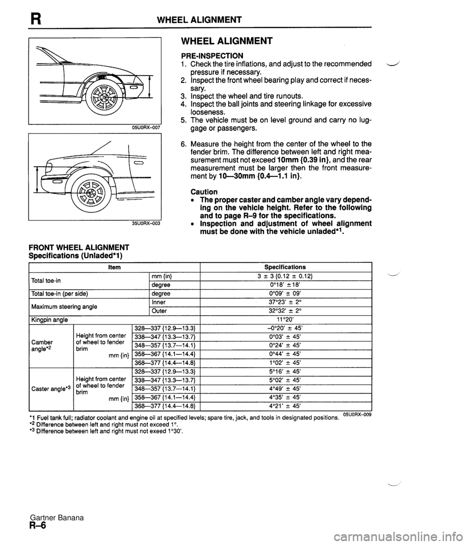
WHEEL ALIGNMENT WHEEL ALIGNMENT FRONT WHEEL ALIGNMENT Specifications (Unladed*l) PRE-INSPECTION 1. Check the tire inflations, and adjust to the recommended d pressure if necessary. 2. lnspect the front wheel bearing play and correct if neces- sary. 3. lnspect the wheel and tire runouts. 4. Inspect the ball joints and steering linkage for excessive looseness. 5. The vehicle must be on level ground and carry no lug- gage or passengers. 6. Measure the height from the center of the wheel to the fender brim. The difference between left and right mea- surement must not exceed 10mm (0.39 in), and the rear measurement must be larger then the front measure- ment by 10-30mm (0.4--1.1 in). Caution The proper caster and camber angle vary depend- ing on the vehicle height. Refer to the following and to page R-9 for the specifications. Inspection and adjustment of wheel alignment must be done with the vehicle unladed*'. . . I Y -- t~otal toe-in l~er side) I 1 dearee 0'09' + 09' I Total toe-in 3 2 3 I0.12 2 0.12) 0'1 8' 2 18' mm (in) dearee Maximum steering angle U - Inner Outer 11 '20' -0°20' 2 45' 0'03' ? 45' 0'24' 2 45' 0°44' -+ 45' 1'02' -+ 45' 5'1 6' ? 45' 5O02' -+ 45' 4O49' 2 45' 4'35' -+ 45' 4'21 ' -+ 45' I Kingpin angle 37"23' -+ 2" 32O32' 2 2" '1 Fuel tank full; radiator coolant and engine oil at specified levels; spare tire, jack, and tools in designated positions. OSUORX-009 ** Difference between left and right must not exceed lo. '3 Difference between left and right must not exeed 1'30'. 328-337 {I 2.9-1 3.3) 338-347 {I 3.3-1 3.7) 340-357 I13.7-14.1) 358-367 {I 4.1-14.4) 36&377 {I 4.4--14.8) 328-337 {I 2.9--13.3) 338-347 {I 3.3-1 3.7) 348-357 113.7-14.1) 358-367 {I 4.1-14.4) 368-377 {I 4.4--14.8) Camber angleg2 Caster angle*3 Height from center Of wheel to fender brim mm {in) Height from center Of wheel to fender brim mm (in) Gartner Banana