radiator MAZDA MX-5 1994 Workshop Manual
[x] Cancel search | Manufacturer: MAZDA, Model Year: 1994, Model line: MX-5, Model: MAZDA MX-5 1994Pages: 1708, PDF Size: 82.34 MB
Page 23 of 1708

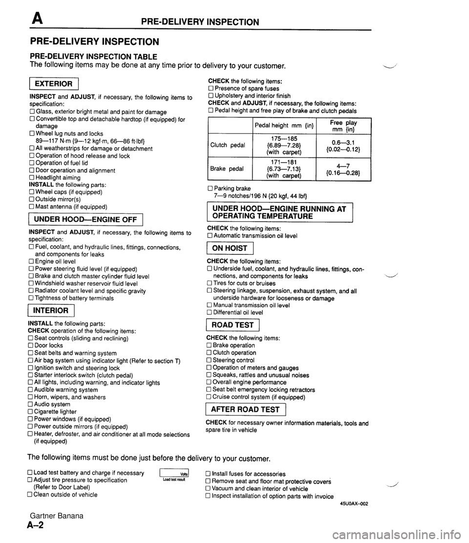
PRE-DELIVERY INSPECTION PRE-DELIVERY INSPECTION PRE-DELIVERY INSPECTION TABLE The following items may be done at any time prior to delivery to your customer. INSPECT and ADJUST, if necessary, the following items to specification: 0 Glass, exterior bright metal and paint for damage 0 Convertible top and detachable hardtop (if equipped) for damage 0 Wheel lug nuts and locks 89-117 N.m (9-1 2 kgf.m, 66-86 ft4bf) 0 All weatherstrips for damage or detachment Operation of hood release and lock Operation of fuel lid 0 Door operation and alignment Headlight aiming INSTALL the following parts: Wheel caps (if equipped) 0 Outside mirror(s) 0 Mast antenna (if equipped) UNDER HOOD-ENGINE OFF INSPECT and ADJUST, if necessary, the following items to specification : Fuel, coolant, and hydraulic lines, fittings, connections, and components for leaks Engine oil level 0 Power steering fluid level (if equipped) Brake and clutch master cylinder fluid level 0 Windshield washer reservoir fluid level 0 Radiator coolant level and specific gravity 0 Tightness of battery terminals pKiq INSTALL the following parts: CHECK operation of the following items: 0 Seat controls (sliding and reclining) 0 Door locks 0 Seat belts and warning system 0 Air bag system using indicator light (Refer to section T) Ignition switch and steering lock 0 Starter interlock switch (clutch pedal) All lights, including warning, and indicator lights 0 Audible warning system 0 Horn, wipers, and washers Audio system 0 Cigarette lighter Power windows (if equipped) 0 Power outside mirrors (if equipped) 0 Heater, defroster, and air conditioner at all mode selections (if equipped) CHECK the following items: Presence of spare fuses 0 Upholstery and interior finish CHECK and ADJUST, if necessary, the following items: 0 Pedal height and free play of brake and clutch pedals I Pedal height mm {in} I Ft: $iy I Clutch pedal {6.89--7.28) (with carpet) Parking brake 7-9 notchesil96 N (20 kgf, 44 Ibf) 0.63.1 (0.024. 12) Brake pedal RUNNING AT OPERATING TEMPERATURE CHECK the following items: 0 Automatic transmission oil level 171-181 (6.73--7.13) (with carpet) I ON HOIST I 4--7 {0.16-0.28} CHECK the following items: 0 Underside fuel, coolant, and hydraulic lines, fittings, con- nections, and components for leaks 4 Tires for cuts or bruises 0 Steering linkage, suspension, exhaust system, and all underside hardware for looseness or damage Manual transmission oil level Differential oil level I ROAD TEST I CHECK the following items: Brake operation Clutch operation 0 Steering control 0 Operation of meters and gauges Squeaks, rattles and unusual noises 0 Overall engine performance Seat belt emergency locking retractors 0 Cruise control system (if equipped) I AFTER ROAD TEST I CHECK for necessary owner information materials, tools and spare tire in vehicle The following items must be done just before the delivery to your customer. 0 Load test battery and charge if necessary -1 Install fuses for accessories Adjust tire pressure to specification Load test fesuk 0 Remove seat and floor mat protective covers (Refer to Door Label) 0 Vacuum and clean interior of vehicle Clean outside of vehicle Inspect installation of option parts with invoice 45UOAX-002 Gartner Banana
Page 42 of 1708

ENGINE TUNE-UP ENGINE TUNE-UP PREPARATION SST I 49 9200 020 Tension gauge, V-ribbed belt For inspection of ignition timing and idle speed For inspection of drive belt tension ENGINE OIL 49 801 9 9AO System selector Warning Continuous exposure with USED engine oil has caused skin cancer in laboratory mice. Protect your skin by washing with soap and water im- mediately after this work. Inspection 1. Be sure the vehicle is on level ground. 2. Warm up the engine to normal operating temperature and stop it. 3. Wait for five minutes. 4. Remove the dipstick and check the oil level and condi- tion. 5. Add or replace oil if necessary. Note The distance between the L and F marks on the dip- stick represents 0.8 L (0.85 US qt, 0.70 Imp qt}. ENGINE COOLANT Inspection Coolant level (engine cold) Warning Removing the radiator cap or the coolant filler cap while the engine is running, or when the engine and radiator are hot is dangerous. Scalding cool- ant and steam can shoot out and cause serious in- jury. It can also damage the engine and cooling system. Turn off the engine and wait until it is cool. Even then, be very careful when removing the cap. Wrap a thick cloth around it and slowly turn it counterclockwise to the first stop. Step back while the pressure escapes. When you're sure all the pressure is gone, press down on the cap-still using a cloth - turn it, and remove it. 1. Verify that the coolant level is near the radiator filler neck. 2. Verify that the coolant level in the coolant reservoir is be- tween the FULL and LOW marks. 3. Add coolant if necessary. Gartner Banana
Page 43 of 1708

ENGINE TUNE-UP V-RIBBED BELT PIS or PIS + A/C EQUIPPED AIC EQUIPPED IDLER Coolant quality 1. Verify that there is no buildup of rust or scale around the radiator cap or radiator filler neck. 2. Verify that the coolant is free of oil. d 3. Replace the coolant if necessary. DRIVE BELT Inspection 1. Remove the air intake pipe. 2. Check the drive belts for wear, cracks, and fraying. Re- place if necessary. 3. Verify that the drive belts are correctly mounted on the pulleys. 4. Check the drive belt deflection when the engine is cold, or at least 30 minutes after the engine has stopped. Ap- ply moderate pressure 98 N (10 kgf, 22 Ibf) midway be- tween the specified pulleys. Deflection rnrn {in) Drive belt New' Used Limit Alternator 5.5-7.0 6.0-7.5 m.22-0.27) (0.24-0.29) 8.0 (0.31) t" NC 8.0-9.0 9'0-'0.0 11.5 {0.45} {0.32-0.35) {0.36-0.39) A belt that has been on a running engine for less than five minutes. 5. If the deflection is not within specification, adjust it. 6. Install the air intake pipe. Drive belt tension check Belt tension can be checked in place of belt deflection. Check the drive belt tension when the engine is cold, or at least 30 minutes after the engine has stopped. Using the SST, check the belt tension between any two pulleys. Gartner Banana
Page 49 of 1708

B ON-VEHICLE MAINTENANCE TIMING BELT Removal / lnstallation 1. Disconnect the negative battery cable. 2. Drain the engine coolant. 3. Remove the under cover. 4. Remove in the order shown in the figure, referring to Removal Note. 5. Install in the reverse order of removal, referring to lnstallation Note. (80-110 kgfmn, 7.9-10.7 Nm 13-17 Nm (125-175 kgfcm, 109-151 In4bf) Nm (kgfm, ft4bf) 45UOBX425 1. Air intake pipe 12. Spark plug 2. Upper radiator hose Removal / Installation ......... section G 3. Water hoses (Connected to thermostat 13. PCV valve housing) 14. Cylinder head cover 4. PIS andlor A/C drive belt 15. Upper timing belt cover Removal 1 Installation ....... page B- 6 16. Middle timing belt cover 5. Alternator drive belt 17. Lower timing belt cover Removal / Installation ....... page 5 6 18. Timing belt 6. Water pump pulley Removal Note ............. page B-13 7. Plate Installation Note ........... page B-14 8. Crankshaft pulley Inspection ................. page 8-58 9. Pulley lock bolt 19. Tensioner, tensioner spring Removal Note ............. page B-13 Installation Note ........... page B-14 /' Installation Note ........... page 51 5 Inspection ................. page 558 10. Pulley boss 20. Idler 11. Ignition coil and high-tension lead Inspection ................. page 8-58 Gartner Banana
Page 52 of 1708

ON-VEHICLE MAINTENANCE B Stem After Installation 10. Loosen the tensioner lock bolt to apply spring tension to the timing belt. 11. Tighten the tensioner lock bolt. Tightening torque: 38-51 N-m (3.8-5.3 kgf.m, 28--38 ftlbf) 12. Install the pulley boss and pulley lock bolt. 13. Turn the crankshaft 2 and 116 turns clockwise and verify that the timing marks are correctly aligned. 14. Measure the timing belt deflection by applying moderate pressure 98 N (10 kgf, 22 Ibf) midway between the cam- shaft pulleys. If the deflection is not correct, repeat from Step 10 above. Deflection: 9.0-11.5mm (0.36-4.45 in) at 98 N (10 kgf, 22 Ibf) Pulley lock bolt Hold the crankshaft with the SST and tighten the pulley lock bolt. Tightening torque: 157-166 N.m (16-17 kgf.m, 116-122 ftlbf) 1. till the radiator with specified amount and type of engine coolant. (Refer to section E.) 2. Connect the negative battery cable. 3. Start the engine and check, and if necessary, adjust the ignition timing. Gartner Banana
Page 56 of 1708

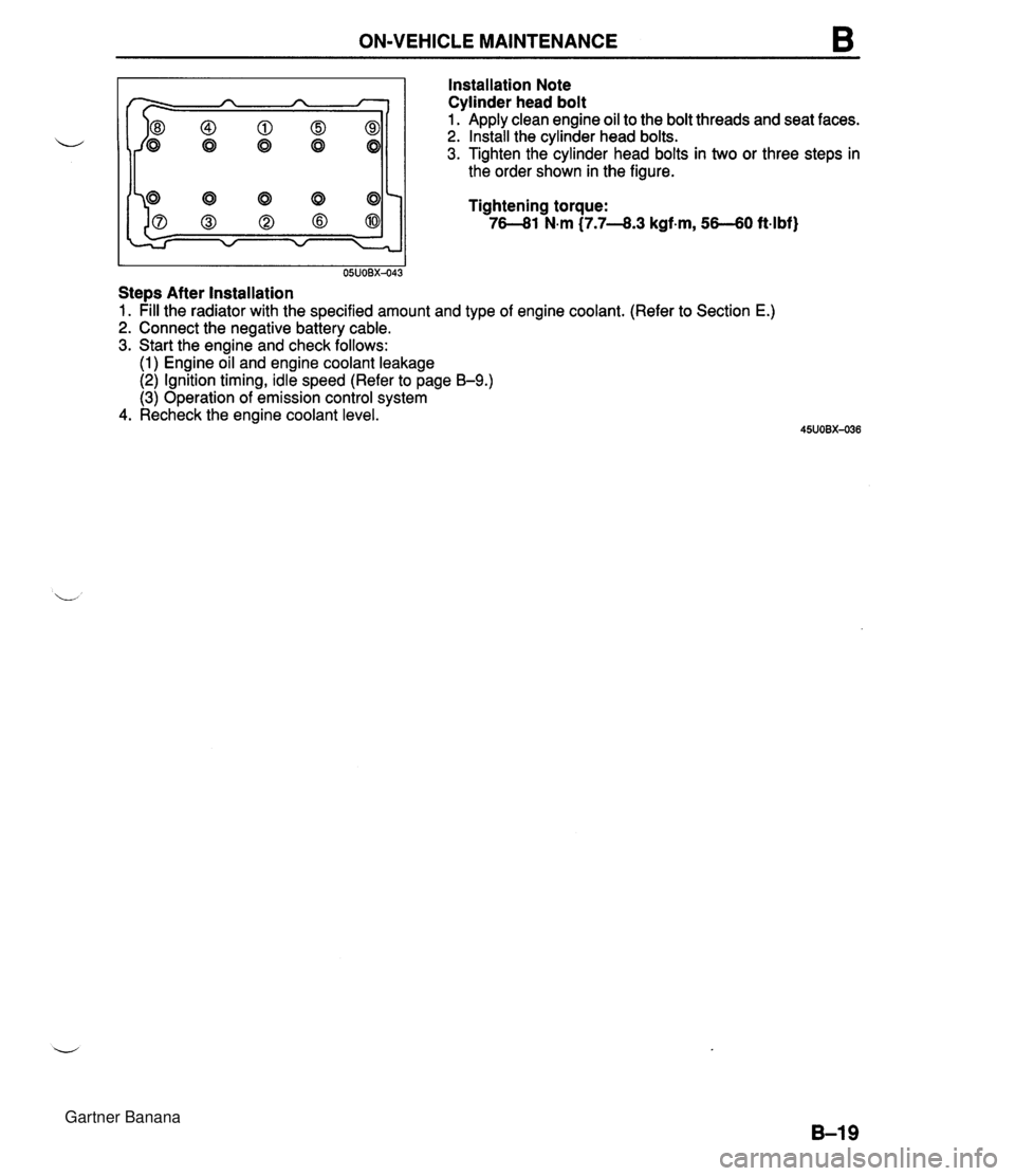
ON-VEHICLE MAINTENANCE B Installation Note Cylinder head bolt I I 05UOBX-043 Stem After Installation Apply clean engine oil to the bolt threads and seat faces. Install the cylinder head bolts. Tighten the cylinder head bolts in two or three steps in the order shown in the figure. Tightening torque: 76-81 N.m (7.7-8.3 kgf-m, 56-60 ft4bf) 1. pill the radiator with the specified amount and type of engine coolant. (Refer to Section E.) 2. Connect the negative battery cable. 3. Start the engine and check follows: (1) Engine oil and engine coolant leakage (2) Ignition timing, idle speed (Refer to page B-9.) (3) Operation of emission control system 4. Recheck the engine coolant level. Gartner Banana
Page 60 of 1708

ON-VEHICLE MAINTENANCE B I I 35UOBX-020 Stem After Installation 3. Install the camshaft pulley lock bolts. 4. Hold the camshaft with a wrench at the cast hexagon. 5. Tighten the camshaft pulley lock bolt. Tightening torque: 50-60 Nm C5.0-6.2 kgfm, 3744 ft4bf) 1. pill the radiator with the specified amount and type of engine coolant. (Refer 2. Connect the negative battery cable. 3. Start the engine and check follows: (1) Engine coolant leakage (2) Ignition timing (Refer to page 59.) 4. Recheck the engine coolant levels. to section E.) Gartner Banana
Page 65 of 1708

B REMOVAL REMOVAL Caution Fuel line spills and leaks are dangerous. Fuel can ignite and cause serious injuries or death -d and damage. Fuel can also irritate skin and eyes. To prevent this, always complete the "Fuel Line safety Procedures" on section F. PROCEDURE 1. Disconnect the negative battery cable. 2. Drain the engine coolant. (Refer to section E.) 3. Remove the transmission. 4. Remove in the order shown in the figure, referring to Removal Note. Step 1 1. Air cleaner housing assembly 2. Accelerator cable 3. Radiator hose 4. Oil cooler hose 5. Coolant reservoir hose 6. Fan connector 7. Radiator and fan assembly 8. PIS andlor A/C drive belt ................ Removal 9. Alternator drive belt .................. Removal page B- 6 10. PIS oil pump (If equipped) ............. Removal Note page 529 11. AIC compressor (If equipped) Removal Note ............. page 529 1 page B- 6 Gartner Banana
Page 123 of 1708

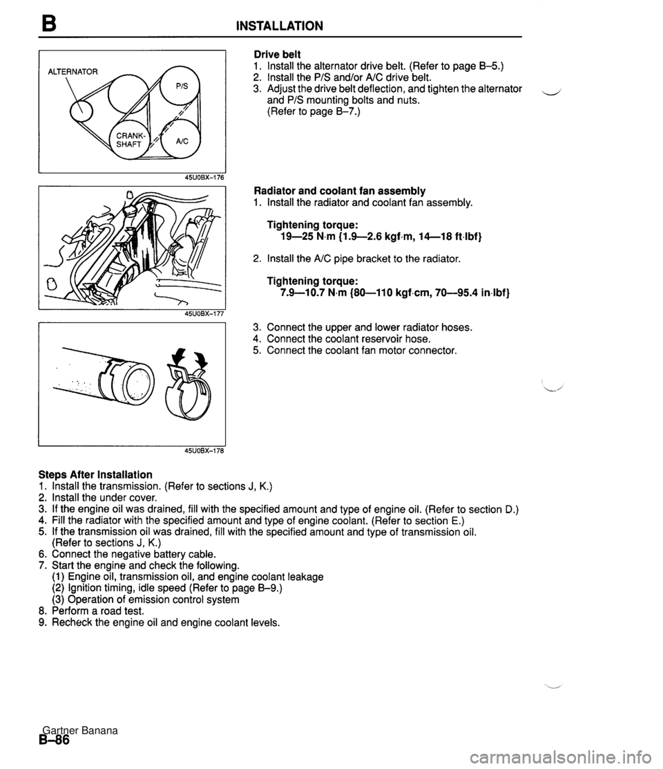
B INSTALLATION ALTERNATOR Drive belt 1. lnstall the alternator drive belt. (Refer to page B-5.) 2. lnstall the PIS and/or AIC drive belt. 3. Adjust the drive belt deflection, and tighten the alternator - and PIS mounting bolts and nuts. (Refer to page 8-7.) Radiator and coolant fan assembly 1. lnstall the radiator and coolant fan assembly. Tightening torque: 19-25 N.m (1.9-2.6 kgf.m, 14--18 ft4bf) 2. lnstall the AIC pipe bracket to the radiator Tightening torque: 7.9-10.7 N.m (80-110 kgf.cm, 70-95.4 in4bf) 3. Connect the upper and lower radiator hoses. 4. Connect the coolant reservoir hose. 5. Connect the coolant fan motor connector. Steps After Installation 1. lhstall the transmission. (Refer to sections J, K.) 2. lnstall the under cover. 3. If the engine oil was drained, fill with the specified amount and type of engine oil. (Refer to section D.) 4. Fill the radiator with the specified amount and type of engine coolant. (Refer to section E.) 5. If the transmission oil was drained, fill with the specified amount and type of transmission oil. (Refer to sections J, K.) 6. Connect the negative battery cable. 7. Start the engine and check the following. (1) Engine oil, transmission oil, and engine coolant leakage (2) Ignition timing, idle speed (Refer to page 59.) (3) Operation of emission control system 8. Perform a road test. 9. Recheck the engine oil and engine coolant levels. Gartner Banana
Page 137 of 1708

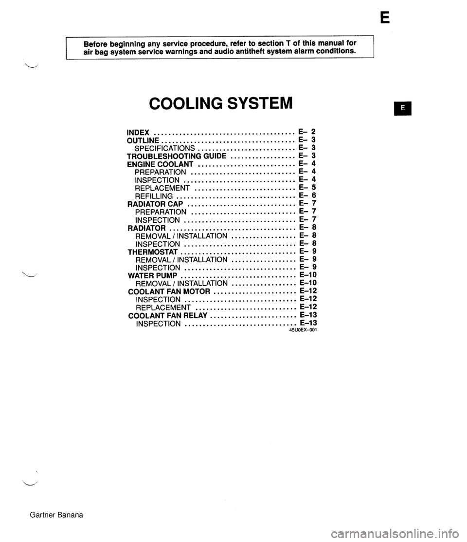
- . - . Before beginning any service procedure, refer to section T of this manual for air bag system service warnings and audio antitheft system alarm conditions . COOLING SYSTEM INDEX ....................................... E- 2 OUTLINE ..................................... E- 3 SPECIFICATIONS ........................... E- 3 TROUBLESHOOTING GUIDE .................. E- 3 ENGINE COOLANT ........................... E- 4 PREPARATION ............................. E- 4 INSPECTION ............................... E- 4 REPLACEMENT ............................ E- 5 REFILLING ................................. E- 6 .............................. RADIATOR CAP E- 7 ............................. PREPARATION E- 7 INSPECTION ............................... E- 7 RADIATOR ................................... E- 8 REMOVAL I INSTALLATION .................. E- 8 INSPECTION ............................... E- 8 THERMOSTAT ................................ E- 9 REMOVAL I INSTALLATION .................. E- 9 INSPECTION ............................... E- 9 WATER PUMP ................................ E-10 REMOVAL / INSTALLATION .................. E-10 COOLANT FAN MOTOR ....................... E-12 INSPECTION ............................... E-12 REPLACEMENT ............................ E-12 ........................ COOLANT FAN RELAY E-13 ............................... INSPECTION E-13 45UOEX-001 Gartner Banana