brake sensor MAZDA MX-5 1997 Factory Repair Manual
[x] Cancel search | Manufacturer: MAZDA, Model Year: 1997, Model line: MX-5, Model: MAZDA MX-5 1997Pages: 514, PDF Size: 17.89 MB
Page 22 of 514
ANTI-LOCK BRAKE SYSTEM
1997 BRAKES Mazda - Anti-Lock
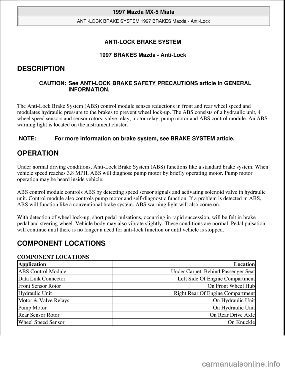
DESCRIPTION
The Anti-Lock Brake System (ABS) control module senses reductions in front and rear wheel speed and
modulates hydraulic pressure to the brakes to prevent wheel lock-up. The ABS consists of a hydraulic unit, 4
wheel speed sensors and sensor rotors, valve relay, motor relay, pump motor and ABS control module. An ABS
warning light is located on the instrument cluster.
OPERATION
Under normal driving conditions, Anti-Lock Brake System (ABS) functions like a standard brake system. When
vehicle speed reaches 3.8 MPH, ABS will diagnose pump motor by briefly operating motor. Pump motor
operation may be heard inside vehicle.
ABS control module controls ABS by detecting speed sensor signals and activating solenoid valve in hydraulic
unit. Control module also controls pump motor and self-diagnostic function. If a problem is detected in ABS,
ABS will function like a conventional brake system. ABS warning light will also come on.
With detection of wheel lock-up, short pedal pulsations, occurring in rapid succession, will be felt in brake
pedal and steering wheel. Vehicle body may also vibrate slightly. These conditions are normal. Pedal pulsation
will continue until there is no longer a need for anti-lock function or until vehicle is stopped.
COMPONENT LOCATIONS
COMPONENT LOCATIONS CAUTION: See ANTI
-LOCK BRAKE SAFETY PRECAUTIONS article in GENERAL
INFORMATION.
NOTE: For more information on brake system, see BRAKE SYSTEM article.
ApplicationLocation
ABS Control ModuleUnder Carpet, Behind Passenger Seat
Data Link ConnectorLeft Side Of Engine Compartment
Front Sensor RotorOn Front Wheel Hub
Hydraulic UnitRight Rear Of Engine Compartment
Motor & Valve RelaysOn Hydraulic Unit
Pump MotorOn Hydraulic Unit
Rear Sensor RotorOn Rear Drive Axle
Wheel Speed SensorOn Knuckle
1997 Mazda MX-5 Miata
ANTI-LOCK BRAKE SYSTEM 1997 BRAKES Mazda - Anti-Lock
1997 Mazda MX-5 Miata
ANTI-LOCK BRAKE SYSTEM 1997 BRAKES Mazda - Anti-Lock
Microsoft
Sunday, July 05, 2009 1:48:48 PMPage 1 © 2005 Mitchell Repair Information Company, LLC.
Microsoft
Sunday, July 05, 2009 1:48:54 PMPage 1 © 2005 Mitchell Repair Information Company, LLC.
Page 27 of 514
(DLC). Set NGS Adapter (49-T088-003) to ABS. Select VEHICLE & ENGINE SELECTION, then select
vehicle model, engine type and model year. Select DIAGNOSTIC DATA LINK. Select ABS-ANTI
LOCK BRAKE MODULE.
2. Select DIAGNOSTIC TEST MODE and note any codes displayed. See DIAGNOSTIC TROUBLE
CODE DESCRIPTION table. Perform appropriate test. See DIAGNOSTIC TROUBLE CODE (DTC)
TESTING . Clear codes after servicing. See CLEARING CODES .
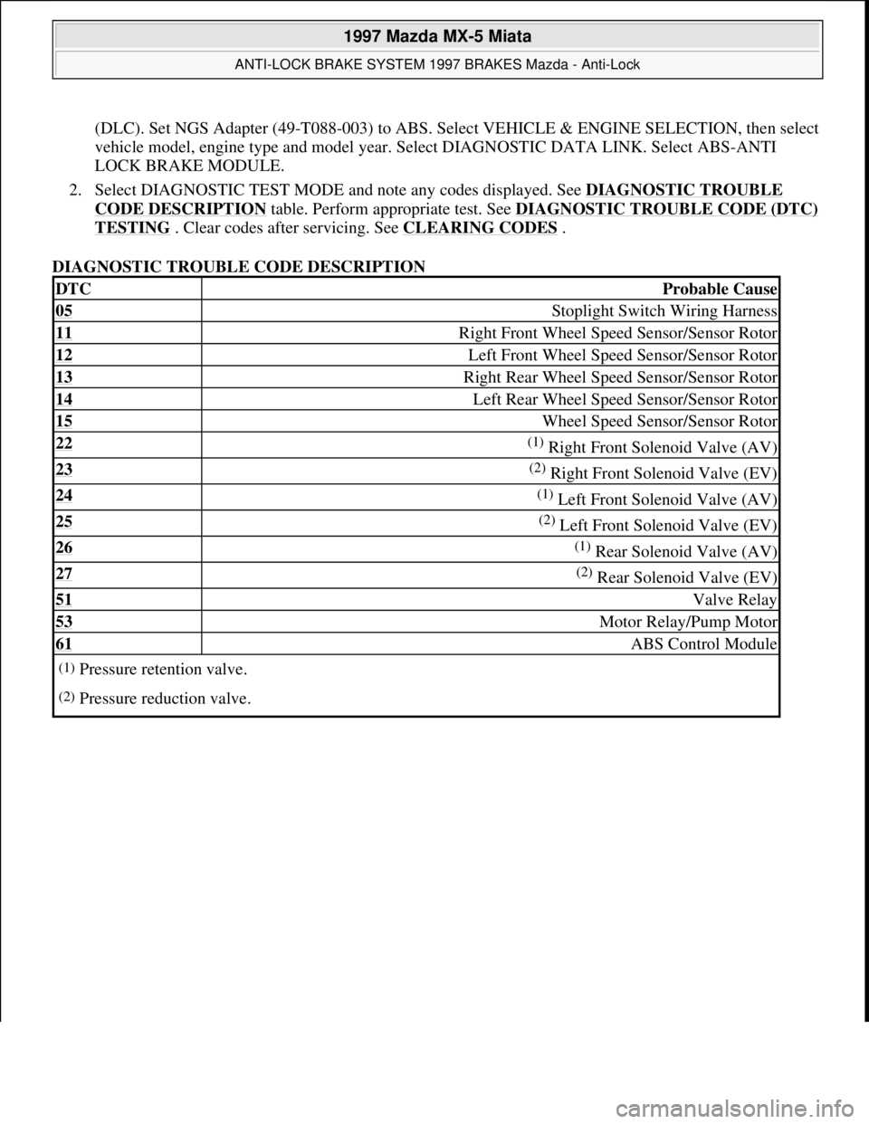
DIAGNOSTIC TROUBLE CODE DESCRIPTION
DTCProbable Cause
05 Stoplight Switch Wiring Harness
11 Right Front Wheel Speed Sensor/Sensor Rotor
12 Left Front Wheel Speed Sensor/Sensor Rotor
13 Right Rear Wheel Speed Sensor/Sensor Rotor
14 Left Rear Wheel Speed Sensor/Sensor Rotor
15 Wheel Speed Sensor/Sensor Rotor
22 (1) Right Front Solenoid Valve (AV)
23 (2) Right Front Solenoid Valve (EV)
24 (1) Left Front Solenoid Valve (AV)
25 (2) Left Front Solenoid Valve (EV)
26 (1) Rear Solenoid Valve (AV)
27 (2) Rear Solenoid Valve (EV)
51 Valve Relay
53 Motor Relay/Pump Motor
61 ABS Control Module
(1)Pressure retention valve.
(2)Pressure reduction valve.
1997 Mazda MX-5 Miata
ANTI-LOCK BRAKE SYSTEM 1997 BRAKES Mazda - Anti-Lock
Microsoft
Sunday, July 05, 2009 1:48:48 PMPage 6 © 2005 Mitchell Repair Information Company, LLC.
Page 29 of 514
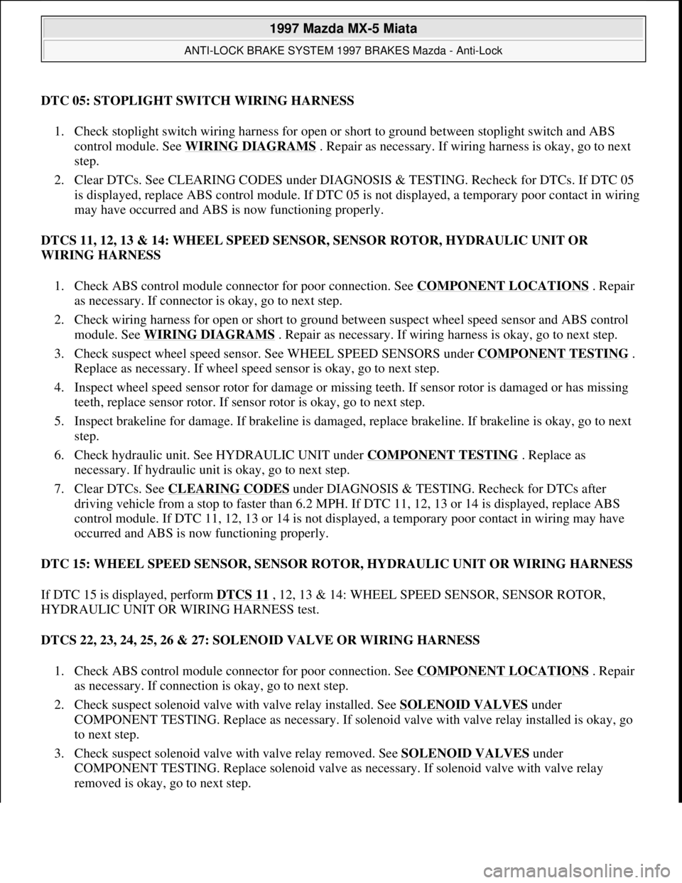
DTC 05: STOPLIGHT SWITCH WIRING HARNESS
1. Check stoplight switch wiring harness for open or short to ground between stoplight switch and ABS
control module. See WIRING DIAGRAMS
. Repair as necessary. If wiring harness is okay, go to next
step.
2. Clear DTCs. See CLEARING CODES under DIAGNOSIS & TESTING. Recheck for DTCs. If DTC 05
is displayed, replace ABS control module. If DTC 05 is not displayed, a temporary poor contact in wiring
may have occurred and ABS is now functioning properly.
DTCS 11, 12, 13 & 14: WHEEL SPEED SENSOR, SENSOR ROTOR, HYDRAULIC UNIT OR
WIRING HARNESS
1. Check ABS control module connector for poor connection. See COMPONENT LOCATIONS
. Repair
as necessary. If connector is okay, go to next step.
2. Check wiring harness for open or short to ground between suspect wheel speed sensor and ABS control
module. See WIRING DIAGRAMS
. Repair as necessary. If wiring harness is okay, go to next step.
3. Check suspect wheel speed sensor. See WHEEL SPEED SENSORS under COMPONENT TESTING
.
Replace as necessary. If wheel speed sensor is okay, go to next step.
4. Inspect wheel speed sensor rotor for damage or missing teeth. If sensor rotor is damaged or has missing
teeth, replace sensor rotor. If sensor rotor is okay, go to next step.
5. Inspect brakeline for damage. If brakeline is damaged, replace brakeline. If brakeline is okay, go to next
step.
6. Check hydraulic unit. See HYDRAULIC UNIT under COMPONENT TESTING
. Replace as
necessary. If hydraulic unit is okay, go to next step.
7. Clear DTCs. See CLEARING CODES
under DIAGNOSIS & TESTING. Recheck for DTCs after
driving vehicle from a stop to faster than 6.2 MPH. If DTC 11, 12, 13 or 14 is displayed, replace ABS
control module. If DTC 11, 12, 13 or 14 is not displayed, a temporary poor contact in wiring may have
occurred and ABS is now functioning properly.
DTC 15: WHEEL SPEED SENSOR, SENSOR ROTOR, HYDRAULIC UNIT OR WIRING HARNESS
If DTC 15 is displayed, perform DTCS 11
, 12, 13 & 14: WHEEL SPEED SENSOR, SENSOR ROTOR,
HYDRAULIC UNIT OR WIRING HARNESS test.
DTCS 22, 23, 24, 25, 26 & 27: SOLENOID VALVE OR WIRING HARNESS
1. Check ABS control module connector for poor connection. See COMPONENT LOCATIONS
. Repair
as necessary. If connection is okay, go to next step.
2. Check suspect solenoid valve with valve relay installed. See SOLENOID VALVES
under
COMPONENT TESTING. Replace as necessary. If solenoid valve with valve relay installed is okay, go
to next step.
3. Check suspect solenoid valve with valve relay removed. See SOLENOID VALVES
under
COMPONENT TESTING. Replace solenoid valve as necessary. If solenoid valve with valve relay
removed is oka
y, go to next step.
1997 Mazda MX-5 Miata
ANTI-LOCK BRAKE SYSTEM 1997 BRAKES Mazda - Anti-Lock
Microsoft
Sunday, July 05, 2009 1:48:48 PMPage 8 © 2005 Mitchell Repair Information Company, LLC.
Page 40 of 514
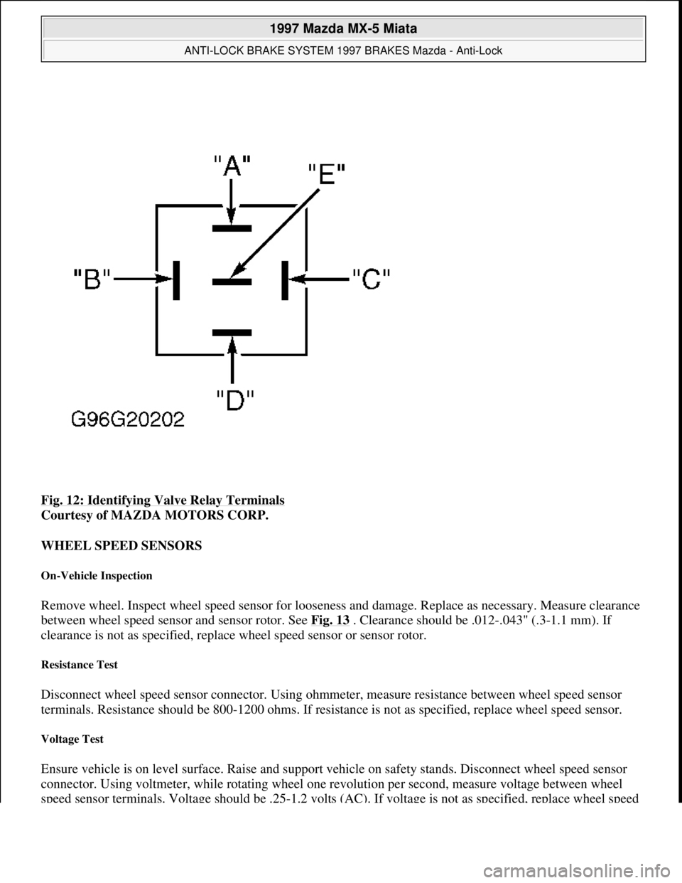
Fig. 12: Identifying Valve Relay Terminals
Courtesy of MAZDA MOTORS CORP.
WHEEL SPEED SENSORS
On-Vehicle Inspection
Remove wheel. Inspect wheel speed sensor for looseness and damage. Replace as necessary. Measure clearance
between wheel speed sensor and sensor rotor. See Fig. 13
. Clearance should be .012-.043" (.3-1.1 mm). If
clearance is not as specified, replace wheel speed sensor or sensor rotor.
Resistance Test
Disconnect wheel speed sensor connector. Using ohmmeter, measure resistance between wheel speed sensor
terminals. Resistance should be 800-1200 ohms. If resistance is not as specified, replace wheel speed sensor.
Voltage Test
Ensure vehicle is on level surface. Raise and support vehicle on safety stands. Disconnect wheel speed sensor
connector. Using voltmeter, while rotating wheel one revolution per second, measure voltage between wheel
speed sensor terminals. Voltage should be .25-1.2 volts (AC). If voltage is not as specified, replace wheel speed
1997 Mazda MX-5 Miata
ANTI-LOCK BRAKE SYSTEM 1997 BRAKES Mazda - Anti-Lock
Microsoft
Sunday, July 05, 2009 1:48:49 PMPage 19 © 2005 Mitchell Repair Information Company, LLC.
Page 41 of 514
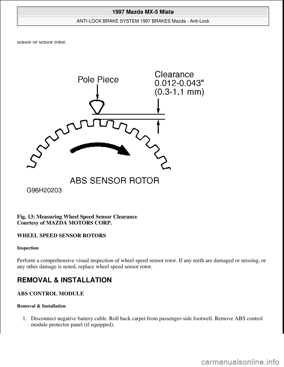
sensor or sensor rotor.
Fig. 13: Measuring Wheel Speed Sensor Clearance
Courtesy of MAZDA MOTORS CORP.
WHEEL SPEED SENSOR ROTORS
Inspection
Perform a comprehensive visual inspection of wheel speed sensor rotor. If any teeth are damaged or missing, or
any other damage is noted, replace wheel speed sensor rotor.
REMOVAL & INSTALLATION
ABS CONTROL MODULE
Removal & Installation
1. Disconnect negative battery cable. Roll back carpet from passenger-side footwell. Remove ABS control
module protector panel (if equipped).
1997 Mazda MX-5 Miata
ANTI-LOCK BRAKE SYSTEM 1997 BRAKES Mazda - Anti-Lock
Microsoft
Sunday, July 05, 2009 1:48:49 PMPage 20 © 2005 Mitchell Repair Information Company, LLC.
Page 42 of 514
2. Disconnect ABS control module electrical connector. Remove ABS control module mounting bolts/nuts.
Remove ABS control module. To install, reverse removal procedure. Tighten ABS control module
mounting bolts/nuts to 61-87 INCH lbs. (6.9-9.8 N.m).
HYDRAULIC UNIT
Removal & Installation
1. Disconnect negative battery cable. Disconnect hydraulic unit electrical connector. Using Flare Nut
Wrench (49-0259-770B), disconnect brakelines from hydraulic unit. Note location of brakelines for
installation reference. Disconnect electrical connectors. Remove hydraulic unit mounting bolts and nuts.
2. Remove hydraulic unit. To install, reverse removal procedure. Tighten mounting bolts and nuts to
specification. See TORQUE SPECIFICATIONS
. Add fluid and bleed air from system. See
BLEEDING BRAKE SYSTEM
.
FRONT WHEEL SPEED SENSOR ROTOR
Removal
Raise and support vehicle. Remove front wheel assemblies. Remove brake caliper and wire aside. Remove
rotor. Remove grease cap and wheel bearing lock nut. Remove wheel hub. Using Puller (49-0839-425C) and
Attachment (49-F027-007), remove wheel speed sensor rotor from hub.
Installation
To install, reverse removal procedure. Tighten bolts and nuts to specification. See TORQUE
SPECIFICATIONS .
REAR WHEEL SPEED SENSOR ROTOR
Removal
Raise and support vehicle. Remove rear wheel assemblies. Remove brake caliper and wire aside. Remove wheel
bearing lock nut. Remove lower control arm-to-rear steering knuckle bolt and nut. Remove drive axle. DO NOT
disassemble drive axle assembly to remove sensor rotor. Replace drive axle assembly.
Installation
To install, reverse removal procedure. Tighten bolts and nuts to specification. See TORQUE
SPECIFICATIONS .
WHEEL SPEED SENSOR
Removal & Installation
Raise and support vehicle. Remove wheel assemblies. Disconnect wheel speed sensor electrical connector.
Remove wheel speed sensor mounting bolt. Remove wheel speed sensor from vehicle. To install, reverse
1997 Mazda MX-5 Miata
ANTI-LOCK BRAKE SYSTEM 1997 BRAKES Mazda - Anti-Lock
Microsoft
Sunday, July 05, 2009 1:48:49 PMPage 21 © 2005 Mitchell Repair Information Company, LLC.
Page 46 of 514
With engine off, depress pedal a few times to eliminate vacuum. Depress brake pedal by hand and check pedal
free play. See BRAKE PEDAL FREE PLAY SPECIFICATIONS
table. Adjust play by loosening push rod
lock nut. Turn push rod until correct free play is obtained. Tighten push rod lock nut to 18-25 ft. lbs. (24-34
N.m).
BRAKE PEDAL FREE PLAY SPECIFICATIONS
PARKING/EMERGENCY BRAKE
1. Depress brake pedal several times. Pull parking brake lever with a force of 44 lbs. (20 kg). If stroke is 7-9
notches, parking brake is properly adjusted. If stroke is not 7-9 notches, raise and support rear of vehicle.
Release parking brake lever.
2. Rotate cable adjusting nut at lever end of cable, located under console cover, until stroke is within
specification. Ensure rear brakes do not drag. Ensure parking brake warning light illuminates when brake
lever is pulled one notch.
TORQUE SPECIFICATIONS
TORQUE SPECIFICATIONS
WIRING DIAGRAMS
ApplicationIn. (mm)
Miata.16-.28 (4-7)
ApplicationFt. Lbs. (N.m)
Brake Caliper Mounting Bolts37-50 (50-68)
Brakeline Nuts10-16 (14-22)
Hydraulic Unit Brakeline Union Bolts18-26 (24-35)
Hydraulic Unit Mounting Bolts/Nuts14-18 (19-24)
I-Arm-To-Rear Steering Knuckle Bolt (RX7)44-54 (59-73)
Lower Control Arm-To-Rear Steering Knuckle Nut47-54 (64-73)
Push Rod Lock Nut18-25 (24-34)
Stoplight Switch Lock Nut10-13 (14-18)
Wheel Bearing Lock Nut
Front123-159 (167-216)
Rear159-217 (216-294)
Wheel Lug Nuts66-86 (89-117)
Wheel Speed Sensor Mounting Bolt12-16 (16-22)
INCH Lbs. (N.m)
ABS Control Unit Mounting Bolts/Nuts61-87 (6.9-9.8)
1997 Mazda MX-5 Miata
ANTI-LOCK BRAKE SYSTEM 1997 BRAKES Mazda - Anti-Lock
Microsoft
Sunday, July 05, 2009 1:48:49 PMPage 25 © 2005 Mitchell Repair Information Company, LLC.
Page 79 of 514
1997-2001 DRIVE AXLES
Axle Shafts - MX-5 Miata
TROUBLE SHOOTING
Inspect CV joint boot on axle shaft for cracks, damage, leaking, grease, and looseness in boot band. Inspect axle
shaft for bending, cracks, and wear of joint splines. Repair or replace as necessary.
REMOVAL & INSTALLATION
AXLE SHAFTS
Removal
1. Raise vehicle and support with safety stands. Remove wheel and tire assembly. Remove axle shaft lock
nut. See Fig. 1
.
2. Remove brake caliper assembly. Remove lower control arm bolt at knuckle, and pull knuckle/hub
assembly outward. Using pry bar between differential housing and inner CV joint, remove inner CV joint
from differential. See Fig. 2
. Remove axle shaft from knuckle/hub assembly. NOTE: See DRIVE AXLE NOISE DIAGNOSIS article in GENERAL INFORMATION.
CAUTION: If vehicle is equipped with ABS, before performing following procedure,
remove ABS wheel speed sensor (axle side) and fix it to an appropriate
place where sensor will not be pulled by mistake while servicing vehicle.
NOTE: If axle shaft will not come out of rear hub support easily, install a discarded nut
onto axle shaft so that nut is flush with end of axle shaft. Tap nut with a copper
hammer to loosen axle shaft from wheel hub.
1997 Mazda MX-5 Miata
1997-2001 DRIVE AXLES Axle Shafts - MX-5 Miata
1997 Mazda MX-5 Miata
1997-2001 DRIVE AXLES Axle Shafts - MX-5 Miata
Microsoft
Sunday, July 05, 2009 1:51:37 PMPage 1 © 2005 Mitchell Repair Information Company, LLC.
Microsoft
Sunday, July 05, 2009 1:51:53 PMPage 1 © 2005 Mitchell Repair Information Company, LLC.
Page 122 of 514
MASTER CYLINDER
Removal & Installation
Disconnect fluid level sensor electrical connector at fluid reservoir. Disconnect and plug brake lines at master
cylinder to prevent entry of dirt and loss of fluid. Remove nuts attaching master cylinder to power brake unit.
Remove master cylinder from vehicle. To install master cylinder, reverse removal procedure. Bleed air from
system.
POWER BRAKE UNIT
Removal & Installation
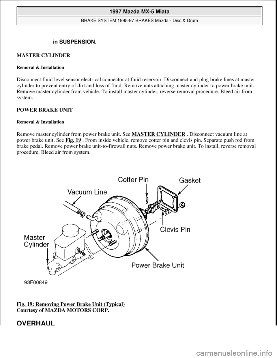
Remove master cylinder from power brake unit. See MASTER CYLINDER . Disconnect vacuum line at
power brake unit. See Fig. 19 . From inside vehicle, remove cotter pin and clevis pin. Separate push rod from
brake pedal. Remove power brake unit-to-firewall nuts. Remove power brake unit. To install, reverse removal
procedure. Bleed air from system.
Fig. 19: Removing Power Brake Unit (Typical)
Courtesy of MAZDA MOTORS CORP.
OVERHAUL
in SUSPENSION.
1997 Mazda MX-5 Miata
BRAKE SYSTEM 1995-97 BRAKES Mazda - Disc & Drum
Microsoft
Sunday, July 05, 2009 1:51:03 PMPage 28 © 2005 Mitchell Repair Information Company, LLC.
Page 197 of 514
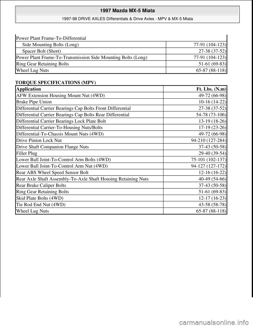
TORQUE SPECIFICATIONS (MPV)
Power Plant Frame-To-Differential
Side Mounting Bolts (Long)77-91 (104-123)
Spacer Bolt (Short)27-38 (37-52)
Power Plant Frame-To-Transmission Side Mounting Bolts (Long)77-91 (104-123)
Ring Gear Retaining Bolts51-61 (69-83)
Wheel Lug Nuts65-87 (88-118)
ApplicationFt. Lbs. (N.m)
AFW Extension Housing Mount Nut (4WD)49-72 (66-98)
Brake Pipe Union10-16 (14-22)
Differential Carrier Bearings Cap Bolts Front Differential27-38 (37-52)
Differential Carrier Bearings Cap Bolts Rear Differential54-78 (73-106)
Differential Carrier Bearings Lock Plate Bolt13-19 (18-26)
Differential Carrier-To-Housing Nuts/Bolts17-19 (23-26)
Differential-To-Chassis Mount Nuts (4WD)49-72 (66-98)
Drive Pinion Lock Nut94-210 (127-284)
Drive Shaft Companion Flange Nuts37-43 (50-58)
Filler Plug29-40 (39-54)
Lower Ball Joint-To-Control Arm Bolts (4WD)75-101 (102-137)
Lower Ball Joint-To-Control Arm Nut (4WD)94-127 (127-172)
Rear ABS Wheel Speed Sensor Bolt12-16 (16-22)
Rear Axle Shaft Assembly-To-Axle Shaft Housing Retaining Nuts40-49 (54-66)
Rear Brake Caliper Bolts37-43 (50-58)
Ring Gear Retaining Bolts51-61 (69-83)
Skid Plate Bolts (4WD)12-17 (16-23)
Tie Rod End Nut (4WD)43-58 (58-78)
Wheel Lug Nuts65-87 (88-118)
1997 Mazda MX-5 Miata
1997-98 DRIVE AXLES Differentials & Drive Axles - MPV & MX-5 Miata
Microsoft
Sunday, July 05, 2009 1:52:42 PMPage 23 © 2005 Mitchell Repair Information Company, LLC.