torque spec MAZDA MX-5 1997 Factory User Guide
[x] Cancel search | Manufacturer: MAZDA, Model Year: 1997, Model line: MX-5, Model: MAZDA MX-5 1997Pages: 514, PDF Size: 17.89 MB
Page 63 of 514
Condition
TCM outputs solenoid pattern of 3rd gear when gear ratio is other than 3rd gear. Possible causes are:
Low ATF level.
Band servo slippage.
Front clutch slippage.
Low line pressure.
Control valve stuck.
Solenoid valve malfunction.
TCM malfunction.
Diagnosis & Repair Procedure
1. Ensure ATF level and condition is okay. Check line pressure and stall speed. See LINE PRESSURE
TEST and STALL SPEED under TESTING in MAZDA NC4A-EL OVERHAUL article. Repair any
components as necessary. If malfunction is not present, go to next step.
2. Inspect 1-2, 2-3 and 3-4 shift solenoid valves. See SOLENOID VALVES
under COMPONENT
TESTING. Repair as needed. If solenoid valves are okay, go to next step.
3. Inspect valve body. Ensure all valves operate smoothly. Repair as needed. If valve body is okay, go to
next step.
4. Clear DTC and retest. See CLEARING CODES
. If DTC P0734 is still present, replace PCM. If code is
no longer present and symptom still exists, problem may be caused by intermittent clutch slippage.
Further investigation may be required. See MAZDA NC4A-EL OVERHAUL article.
DTC P0740: TORQUE CONVERTER CLUTCH MALFUNCTION
Condition
TCM outputs TCC signal, but TCC does not operate. Possible causes are:
Low ATF level.
Low line pressure.
Torque converter slippage.
Control valve stuck.
Lock-up solenoid valve malfunction.
TCM malfunction.
Diagnosis & Repair Procedure
NOTE: If any following DTC is also present, repair it first and then proceed with this
test: DTC P0750
, P0755 , P0760 .
1997 Mazda MX-5 Miata
1997 AUTOMATIC TRANSMISSIONS NC4A-EL Electronic Controls
Microsoft
Sunday, July 05, 2009 1:35:04 PMPage 15 © 2005 Mitchell Repair Information Company, LLC.
Page 64 of 514
1. Inspect ATF level and condition. Correct as needed. If fluid level and condition is okay, check line
pressure. See LINE PRESSURE TEST under TESTING in MAZDA NC4A-EL OVERHAUL article.
Follow repair recommendations if line pressure is not within specifications. If line pressure is okay, go to
next step.
2. Inspect lock-up solenoid. See SOLENOID VALVES
under COMPONENT TESTING. Repair as
needed. If solenoid valve is okay, go to next step.
3. Inspect lock-up control valve in valve body. If valve is okay, go to next step.
4. Using an EC-AT tester connected to TCM, ensure that engine speed and turbine speed during TCC lock-
up in 4th gear are the same. If speeds are different, replace torque converter. If speeds are the same, go to
next step.
5. Clear DTC. See CLEARING CODES
. Retrieve DTC. If DTC P0740 is still present, replace TCM. If
code is no longer present and symptom still exists, problem may be caused by intermittent TCC slippage.
Further investigation may be required. See MAZDA NC4A-EL OVERHAUL article.
DTC P0750: 1-2 SHIFT SOLENOID MALFUNCTION
Possible Causes:
Short or open circuit between TCM and solenoid.
TCM malfunction.
Shift solenoid malfunction.
Diagnosis & Repair Procedure
1. Ensure all connections are clean and tight. Repair as needed. Turn ignition on. Access TCM connectors.
Using voltmeter, backprobe harness connectors. DO NOT disconnect connectors. Go to next step.
2. Measure voltage between ground and terminal No. 2E (Blue/Yellow wire) on TCM connector. During
test drive, voltage should be less than one volt when solenoid is off and battery voltage when solenoid is
on. See SOLENOID OPERATION
table under TCM OUTPUT DEVICES. If voltage is within
specification, go to step 5 . If voltage is not within specification, go to next step.
3. Turn ignition off. Disconnect TCM harness connector. Measure resistance between ground and terminal
No. 2E. If resistance is 13-27 ohms at 68°F (20°C), go to step 5 . If resistance is not 13-27 ohms at 68°F
(20°C), go to next step.
4. Inspect 1-2 shift solenoid and related circuits. See SOLENOID VALVES
under COMPONENT
TESTING. Repair as needed. If solenoid valve and related circuits are okay, go to next step.
5. Clear DTC and road test vehicle. Retrieve DTC. If DTC P0750 is still present, replace TCM. If code is no
longer present, system is okay.
DTC P0755: 2-3 SHIFT SOLENOID MALFUNCTION
Possible Causes:
Short or open circuit between TCM and solenoid.
TCM malfunction.
1997 Mazda MX-5 Miata
1997 AUTOMATIC TRANSMISSIONS NC4A-EL Electronic Controls
Microsoft
Sunday, July 05, 2009 1:35:04 PMPage 16 © 2005 Mitchell Repair Information Company, LLC.
Page 66 of 514
Condition
Vehicle speed sensor signal is not input to TCM. Possible causes are:
Vehicle speed sensor malfunction.
Vehicle speedometer sensor malfunction.
Damaged circuits or connectors between sensors and TCM.
Diagnosis & Repair Procedure
1. Ensure all connections are clean and tight. Repair as needed. Turn ignition on. Using voltmeter,
backprobe TCM harness connector. DO NOT disconnect connector. Test drive vehicle.
2. Measure voltage between ground and terminal No. 1P (Green/Red wire) on TCM harness connector.
During test drive voltage should be about 4 volts. When parked, voltage should be less than 1.5 or 7-9
volts. If voltage is within specifications, go to step 5 . If voltage is not within specifications, go to next
step.
3. Turn ignition off. Disconnect negative battery cable. Remove instrument cluster. Disconnect TCM
harness connectors. Ensure continuity exists on Green/Red wire between terminal No. 1P on TCM
connector and terminal No. 2F on instrument cluster harness left connector. Repair as needed. If
continuity exists, go to next step.
4. With combination meter removed, measure voltage between terminals No. 2F and 2D on combination
meter connector using analog voltmeter. Raise and support vehicle. Rotate rear wheels. If voltage pulse is
present, go to next step. If voltage pulse is not present, inspect speedometer cable. Replace as needed. If
cable is okay, replace combination meter or circuit board (as applicable).
5. Clear codes and road test vehicle. Retrieve DTC. If DTC 1720 is still present, replace TCM. If code is no
longer present, problem may be caused by poor connection. Repair as needed.
DTC P1743: TORQUE CONVERTER CLUTCH (TCC) SOLENOID MALFUNCTION
Possible Causes:
Short or open circuit between TCM and solenoid.
TCM malfunction.
Lock-up solenoid malfunction.
Diagnosis & Repair Procedure
1. Ensure all connections are clean and tight. Repair as needed. Turn ignition on. Access TCM connectors.
Using voltmeter, backprobe harness connectors. DO NOT disconnect connectors. Go to next step.
2. Measure voltage between ground and terminal No. 2K (Yellow/Black wire). Battery voltage should be
present with solenoid on and zero volts with solenoid off. If voltage is within specifications, go to step 5 .
If voltage is not within specifications, go to next step.
3. Turn ignition off. Disconnect TCM harness connector. Measure resistance between ground and terminal
No. 2K. If resistance is 13-25 ohms at 68°F (20°C), go to step 5 . If resistance is not 13-25 ohms at 68°F
(20°C),
go to next step.
1997 Mazda MX-5 Miata
1997 AUTOMATIC TRANSMISSIONS NC4A-EL Electronic Controls
Microsoft
Sunday, July 05, 2009 1:35:04 PMPage 18 © 2005 Mitchell Repair Information Company, LLC.
Page 81 of 514
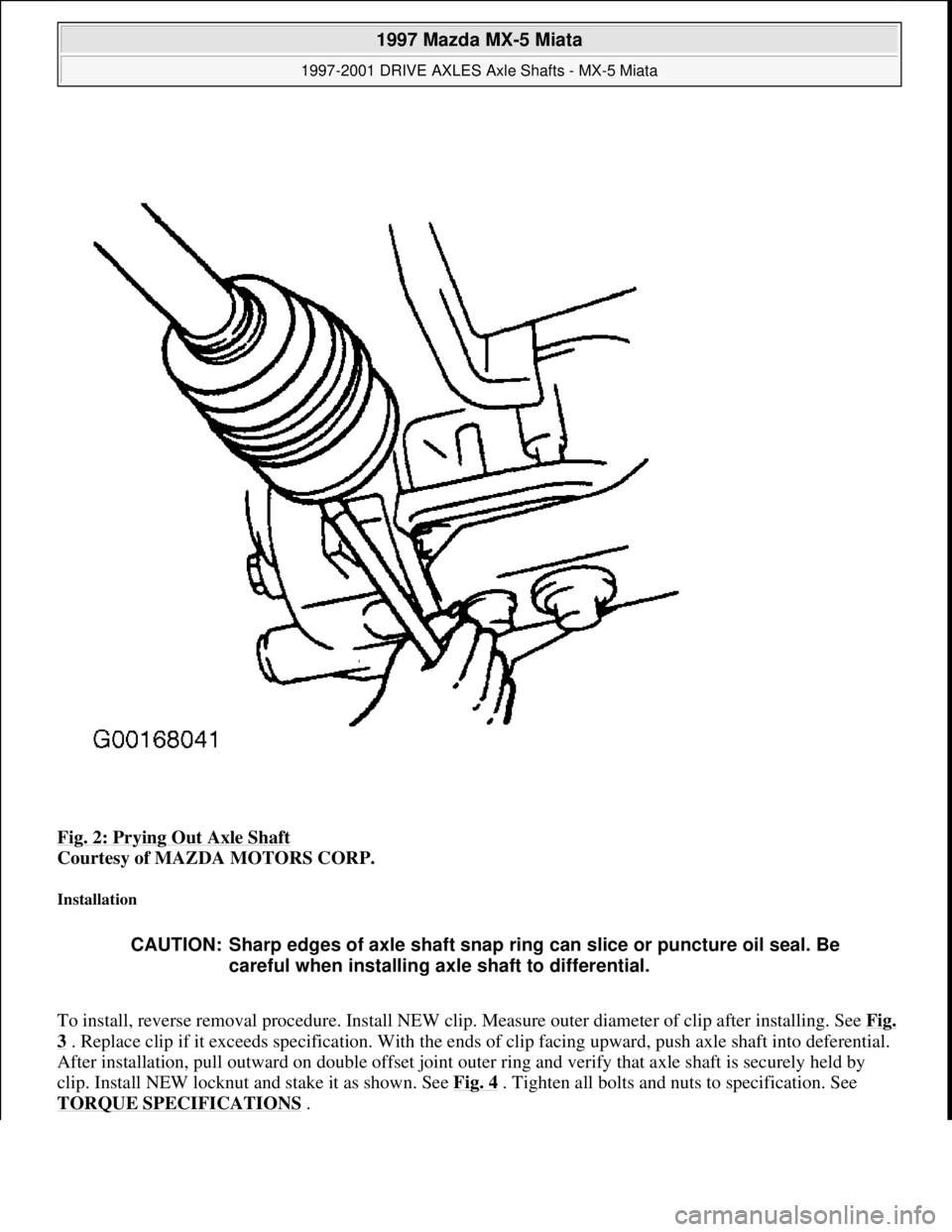
Fig. 2: Prying Out Axle Shaft
Courtesy of MAZDA MOTORS CORP.
Installation
To install, reverse removal procedure. Install NEW clip. Measure outer diameter of clip after installing. See Fig.
3 . Replace clip if it exceeds specification. With the ends of clip facing upward, push axle shaft into deferential.
After installation, pull outward on double offset joint outer ring and verify that axle shaft is securely held by
clip. Install NEW locknut and stake it as shown. See Fig. 4
. Tighten all bolts and nuts to specification. See
TORQUE SPECIFICATIONS
.
CAUTION: Sharp edges of axle shaft snap ring can slice or puncture oil seal. Be
careful when installing axle shaft to differential.
1997 Mazda MX-5 Miata
1997-2001 DRIVE AXLES Axle Shafts - MX-5 Miata
Microsoft
Sunday, July 05, 2009 1:51:37 PMPage 3 © 2005 Mitchell Repair Information Company, LLC.
Page 93 of 514
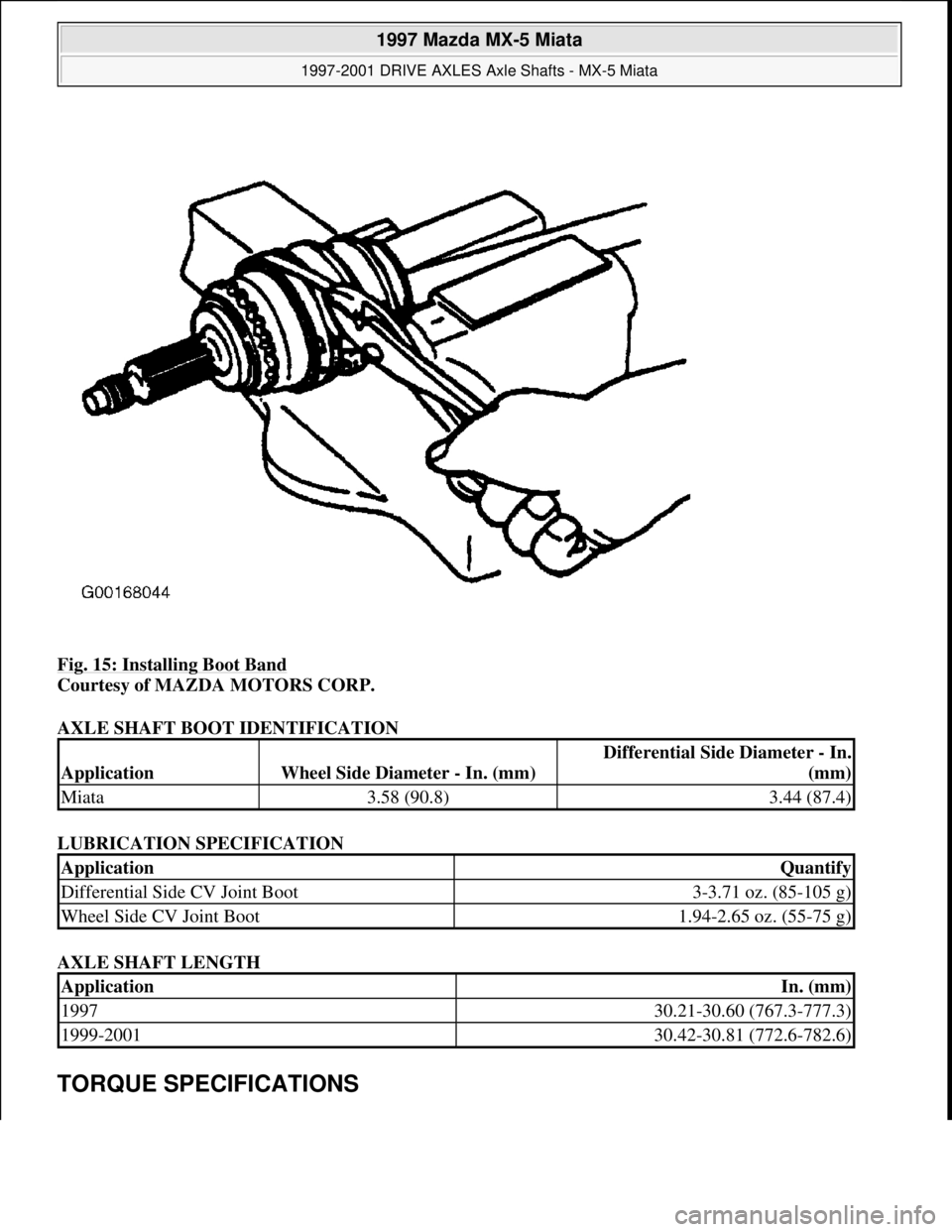
Fig. 15: Installing Boot Band
Courtesy of MAZDA MOTORS CORP.
AXLE SHAFT BOOT IDENTIFICATION
LUBRICATION SPECIFICATION
AXLE SHAFT LENGTH
TORQUE SPECIFICATIONS
ApplicationWheel Side Diameter - In. (mm)
Differential Side Diameter - In.
(mm)
Miata3.58 (90.8)3.44 (87.4)
ApplicationQuantify
Differential Side CV Joint Boot3-3.71 oz. (85-105 g)
Wheel Side CV Joint Boot1.94-2.65 oz. (55-75 g)
ApplicationIn. (mm)
199730.21-30.60 (767.3-777.3)
1999-200130.42-30.81 (772.6-782.6)
1997 Mazda MX-5 Miata
1997-2001 DRIVE AXLES Axle Shafts - MX-5 Miata
Microsoft
Sunday, July 05, 2009 1:51:38 PMPage 15 © 2005 Mitchell Repair Information Company, LLC.
Page 94 of 514
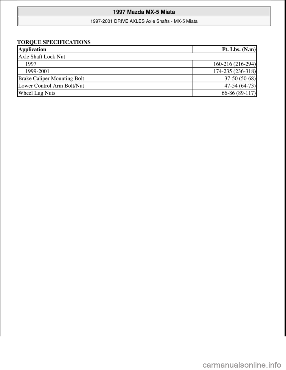
TORQUE SPECIFICATIONS
ApplicationFt. Lbs. (N.m)
Axle Shaft Lock Nut
1997160-216 (216-294)
1999-2001174-235 (236-318)
Brake Caliper Mounting Bolt37-50 (50-68)
Lower Control Arm Bolt/Nut47-54 (64-73)
Wheel Lug Nuts66-86 (89-117)
1997 Mazda MX-5 Miata
1997-2001 DRIVE AXLES Axle Shafts - MX-5 Miata
Microsoft
Sunday, July 05, 2009 1:51:38 PMPage 16 © 2005 Mitchell Repair Information Company, LLC.
Page 117 of 514
caliper. Remove rear brake pads. See REAR DISC BRAKE PADS. Remove remaining caliper guide
bolt. Remove brake caliper from caliper mount. To install, reverse removal procedure. Bleed air from
system.
Removal & Installation (MX-3)
1. Raise and support rear of vehicle. Remove rear wheel assemblies. Release parking brake and disconnect
parking brake cable from caliper. Disconnect brake flexhose from caliper. See Fig. 13
.
2. Remove upper caliper mounting bolt. Rotate caliper downward. Remove "V" spring, pads, shims and
guide plates. Replace brake pads if pad lining thickness is less than .04" (1.0 mm).
3. Remove lower caliper mounting bolt. Pull caliper toward center of vehicle to slide it off of caliper mount.
To install, reverse removal procedure. Using Brake Piston Wrench (49 FA18 602), turn wrench clockwise
until piston bottoms out in brake caliper. Bleed air from system.
REAR BRAKE ROTOR
Removal & Installation (Miata, Millenia, MPV, MX-3, MX-6, Protege, RX7, 626 & 929)
1. Raise and support vehicle. Remove rear wheel assemblies. Remove rear brake caliper with brake hose
connected. See REAR BRAKE CALIPER
. Support caliper using wire. Remove rotor-to-hub screws (if
equipped). Remove rotor.
2. Machine rotor if lateral runout exceeds specification. Replace rotor if measured thickness is less than
specified minimum thickness. See DISC BRAKE SPECIFICATIONS
.
3. To install, reverse removal procedure. Check end play at grease cap. On 929, if end play
exceeds .004" (.10 mm), check lock nut torque or replace wheel bearings. On all other models, if end play
exceeds .002" (.05 mm), check lock nut torque or replace wheel bearings.
REAR BRAKE SHOES & WHEEL CYLINDERS
Removal (B2300, B3000 & B4000)
1. Raise and support vehicle. Remove rear wheel assemblies. Remove brake drum. Machine or replace drum
as necessary if inner diameter is not as specified. See DRUM BRAKE SPECIFICATIONS
.
2. Place a wheel cylinder clamp over ends of wheel cylinder. Disengage adjusting lever from adjusting
screw by pulling backwards on self adjuster cable. See Fig. 15
.
3. Move outboard side of adjusting screw upward and back off pivot nut as far as possible. Pull adjusting
lever, cable and adjusting lever spring down and toward rear to unhook pivot hook from large hole in
secondary shoe. DO NOT pry pivot hook from hole.
4. Remove adjusting lever spring and adjusting lever. Remove secondary shoe-to-retracting spring. Remove
primary shoe-to-retracting spring. Unhook cable anchor and remove anchor pin plate.
5. Note color and position of shoe hold-down springs for reassembly. Remove cable guide, shoe hold-down
springs, brake shoes, adjusting screw, pivot nut and socket. Remove parking brake link spring and link.
6. Disconnect parking brake cable from lever. Remove secondary shoe. Disassemble parking brake lever
from shoe by removing retaining clip and spring washer. See Fig. 16
. Remove brake cylinder-to-shoe
connectin
g links. Disconnect brake line from brake cylinder. Remove brake cylinder.
1997 Mazda MX-5 Miata
BRAKE SYSTEM 1995-97 BRAKES Mazda - Disc & Drum
Microsoft
Sunday, July 05, 2009 1:51:03 PMPage 23 © 2005 Mitchell Repair Information Company, LLC.
Page 132 of 514
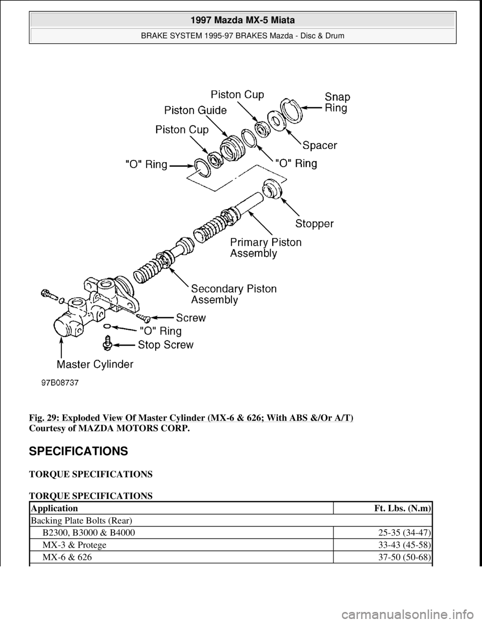
Fig. 29: Exploded View Of Master Cylinder (MX-6 & 626; With ABS &/Or A/T)
Courtesy of MAZDA MOTORS CORP.
SPECIFICATIONS
TORQUE SPECIFICATIONS
TORQUE SPECIFICATIONS
ApplicationFt. Lbs. (N.m)
Backing Plate Bolts (Rear)
B2300, B3000 & B400025-35 (34-47)
MX-3 & Protege33-43 (45-58)
MX-6 & 62637-50 (50-68)
1997 Mazda MX-5 Miata
BRAKE SYSTEM 1995-97 BRAKES Mazda - Disc & Drum
Microsoft
Sunday, July 05, 2009 1:51:03 PMPage 38 © 2005 Mitchell Repair Information Company, LLC.
Page 161 of 514

Installation (B2300, B2500, B3000 & B4000)
1. Lightly coat input shaft splines, release bearing, and fork contact areas with molybdenum disulfide
grease. Align clutch cover dowel holes with flywheel dowels. Tighten clutch cover bolts evenly in a
crisscross pattern to specification. See TORQUE SPECIFICATIONS
.
2. Raise transmission into position. Install and tighten transmission-to-engine block bolts. See TORQUE
SPECIFICATIONS . Install crossmember.
3. On 4WD models, install NEW transfer case gasket. Install transfer case. Tighten transfer case bolts to
specification is sequence. See Fig. 3
. See TORQUE SPECIFICATIONS .
4. On all models, to complete installation, reverse removal procedure. Bleed hydraulic clutch system. See
HYDRAULIC SYSTEM BLEEDING
under ADJUSTMENTS.
Fig. 3: Tightening Transfer Case Bolts (B2300, B2500, B3000 & B4000)
Courtesy of MAZDA MOTORS CORP.
Removal (Miata)
1. Disconnect negative battery cable. Remove gearshift knob, console, and shift lever. See Fig. 4. Raise and
support vehicle. Remove engine undercover. Disconnect exhaust pipe from manifold. Mark drive shaft
flanges for installation reference. Remove drive shaft.
1997 Mazda MX-5 Miata
CLUTCH 1997-98 CLUTCHES Mazda - RWD
Microsoft
Sunday, July 05, 2009 1:36:47 PMPage 5 © 2005 Mitchell Repair Information Company, LLC.
Page 166 of 514
Installation (Miata)
1. Lightly coat input shaft splines, release bearing, and fork contact areas with molybdenum disulfide
grease. Align clutch cover dowel holes with flywheel dowels. Tighten clutch cover bolts evenly in a
crisscross pattern to specification. See TORQUE SPECIFICATIONS
.
2. Place a wooden block on jack, and position jack under front of oil pan. Raise front of engine to ease
transmission installation. Install transmission. Tighten transmission-to-engine block bolts to specification.
See TORQUE SPECIFICATIONS
. Place jack (from front of engine) under transmission.
3. Raise transmission until level with engine. Position Power Plant Frame (PPF) in place. Install
PPF/differential mounting spacer, and tighten bolts to 27-38 ft. lbs. (37-51 N.m). Install and tighten PPF
side mounting bolts.
4. Install sleeve into PPF housing block. Install spacer and bolts. Install reamer bolt into front hole, and
tighten bolt. See Fig. 5
.
5. Install transmission-to-PPF bracket. Install remaining PPF bolts, and tighten to specification. See
TORQUE SPECIFICATIONS
. To complete installation, reverse removal procedure.
RELEASE BEARING & FORK
Removal (B2300, B2500, B3000 & B4000)
With transmission removed, twist release bearing and carrier assembly until preload spring pushes bearing
assembly from slave cylinder. See Fig. 8
.
Installation
Lubricate bearing bore and bearing carrier with NIGI No. 2 (lithium base) grease. Push release bearing
assembl
y onto clutch slave cylinder. NOTE: Front PPF-to-differential side mounting bolt is the reamer bolt, used to
align frame.
NOTE: Use only lithium base grease on release bearing. DO NOT use petroleum base
lubricants.
1997 Mazda MX-5 Miata
CLUTCH 1997-98 CLUTCHES Mazda - RWD
Microsoft
Sunday, July 05, 2009 1:36:47 PMPage 10 © 2005 Mitchell Repair Information Company, LLC.