ECU MAZDA MX-5 1997 Factory Repair Manual
[x] Cancel search | Manufacturer: MAZDA, Model Year: 1997, Model line: MX-5, Model: MAZDA MX-5 1997Pages: 514, PDF Size: 17.89 MB
Page 16 of 514
1. Disable air bag system. See DISABLING & ACTIVATING AIR BAG SYSTEM . Remove meter
hood. Ensure instrument cluster 12 pin connector is securely connected and that terminal No. 1 E is not
damaged. Check continuity between terminal No. 1E of 12 pin cluster connector and terminal No. 2K of
print plate of instrument cluster. If there is continuity, go to next step. If there is no continuity, replace
print plate and then go to next step.
2. Disable air bag system. See DISABLING & ACTIVATING AIR BAG SYSTEM
. Check if terminal
No. Q of 21 pin SAS unit connector is securely connected and is not damaged. If ok, go to next step. If
terminal Q is not securely connected or is damaged, replace air bag harness, then go to next step.
3. Disconnect 21 pin SAS unit connector and 12 pin instrument cluster connector. Check continuity between
terminal No. Q of SAS unit connector and terminal No. 1 E of instrument cluster connector. If there is
continuity, replace SAS unit and then go to next step. See SAS UNIT
under REMOVAL &
INSTALLATION. If there is no continuity, go to next step.
4. Activate air bag system. See DISABLING & ACTIVATING AIR BAG SYSTEM
. Check AIR BAG
warning light for proper system function. See SYSTEM OPERATION CHECK
.
WARNING LIGHT DOES NOT COME ON
Disable air bag system. See DISABLING & ACTIVATING AIR BAG SYSTEM
. Remove meter hood.
Ensure instrument cluster 12 pin connector is securely connected and that terminal No. 1 E is not damaged.
Check continuity between terminal No. 1E of 12 pin cluster connector and terminal No. 2K of print plate of
instrument cluster. If there is continuity, go to next step. If there is no continuity, replace print plate and then go
to next step.
WARNING LIGHT REMAINS ON
1. Measure battery voltage. If voltage is more than 9 volts, go to next step. If voltage is not more than 9
volts, check charging system.
2. Disable air bag system. See DISABLING & ACTIVATING AIR BAG SYSTEM
. Remove dashboard.
Remove heater unit. Check if SAS unit connector is securely connected. Check short bar between SAS
unit terminal No. Q and terminal No. S. If short bar is bent, replace wiring harness and then go to next
step. If short bar is OK, go to next step.
3. Check short bar hook on SAS unit. If hook is OK, go to next step. If hook is damaged, replace SAS unit.
See SAS UNIT
under REMOVAL & INSTALLATION.
4. Disconnect SAS unit 21 pin connector and instrument panel 12 pin connector. Carefully insert an
insulation material between terminal No. Q and terminal No. S of SAS unit so short bar cannot move. NOTE: For connector terminal identification, see WIRING DIAGRAM
.
NOTE: For connector terminal identification, see WIRING DIAGRAM
.
NOTE: For connector terminal identification, see WIRING DIAGRAM
.
NOTE: Use care not to damage short bar when inserting insulation material.
1997 Mazda MX-5 Miata
AIR BAG RESTRAINT SYSTEM 1997 ACCESSORIES/SAFETY EQUIPMENT Mazda - Air Bag Restraint System
Microsoft
Sunday, July 05, 2009 1:40:48 PMPage 16 © 2005 Mitchell Repair Information Company, LLC.
Page 17 of 514
5. Check continuity between terminal No. Q and ground. If continuity exists, replace or repair wiring
harness between instrument cluster and SAS unit. If no continuity exists, replace SAS unit. See SAS
UNIT under REMOVAL & INSTALLATION.
6. Activate air bag system and perform SYSTEM OPERATION CHECK
. Check that AIR BAG warning
light is operating properly. If not, reconfirm malfunction symptoms.
DTC 0 - SAS UNIT
1. Disable system. See DISABLING & ACTIVATING AIR BAG SYSTEM
. Remove dashboard.
Remove heater unit. Check if SAS unit connector is securely connected. If not, reconnect connector and
go next step. If ok, go to next step.
2. Disconnect SAS unit connector and check for continuity between terminal No. V and terminal No. Y of
SAS unit connector. If there is continuity, replace SAS unit. If there is no continuity, replace wiring
harness. Perform SYSTEM OPERATION CHECK
.
DTC 3 - BATTERY
1. Check that battery voltage is at least 8 volts. If not, check battery and/or charging system. Turn ignition
on and check voltage at joint connector terminals A or E (X-33).
2. If voltage is over 8 volts, replace SAS unit. See SAS UNIT
under REMOVAL & INSTALLATION. If
voltage is not over 8 volts, replace wiring harness from battery to fuse box. Perform SYSTEM
OPERATION CHECK .
DTC 6 - DRIVER-SIDE AIR BAG MODULE
1. Disable air ba
g system. See procedures under DISABLING & ACTIVATING AIR BAG SYSTEM. NOTE: When air bag warning light remains on, it can indicate a DTC 0 caused by no
continuity between terminal No. V and terminal No. Y of SAS unit This can be
due to a damaged SAS unit, an open or short circuit in wiring harness or poor
connections.
NOTE: For connector terminal identification, see WIRING DIAGRAM
.
NOTE: When voltage supplied to SAS unit is less than 1 volt due to weak battery, open
or short in wiring harness, poor connection of connector or damaged SAS unit,
DTC 3 will set
NOTE: For connector terminal identification, see WIRING DIAGRAM
.
NOTE: When resistance Is detected between terminals M-O of SAS unit is NOT 2 ohms,
DTC 6 will set.
NOTE: For connector terminal identification, see WIRING DIAGRAM
.
1997 Mazda MX-5 Miata
AIR BAG RESTRAINT SYSTEM 1997 ACCESSORIES/SAFETY EQUIPMENT Mazda - Air Bag Restraint System
Microsoft
Sunday, July 05, 2009 1:40:48 PMPage 17 © 2005 Mitchell Repair Information Company, LLC.
Page 81 of 514
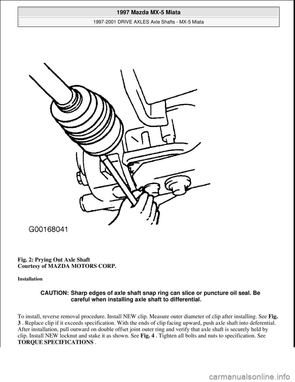
Fig. 2: Prying Out Axle Shaft
Courtesy of MAZDA MOTORS CORP.
Installation
To install, reverse removal procedure. Install NEW clip. Measure outer diameter of clip after installing. See Fig.
3 . Replace clip if it exceeds specification. With the ends of clip facing upward, push axle shaft into deferential.
After installation, pull outward on double offset joint outer ring and verify that axle shaft is securely held by
clip. Install NEW locknut and stake it as shown. See Fig. 4
. Tighten all bolts and nuts to specification. See
TORQUE SPECIFICATIONS
.
CAUTION: Sharp edges of axle shaft snap ring can slice or puncture oil seal. Be
careful when installing axle shaft to differential.
1997 Mazda MX-5 Miata
1997-2001 DRIVE AXLES Axle Shafts - MX-5 Miata
Microsoft
Sunday, July 05, 2009 1:51:37 PMPage 3 © 2005 Mitchell Repair Information Company, LLC.
Page 159 of 514
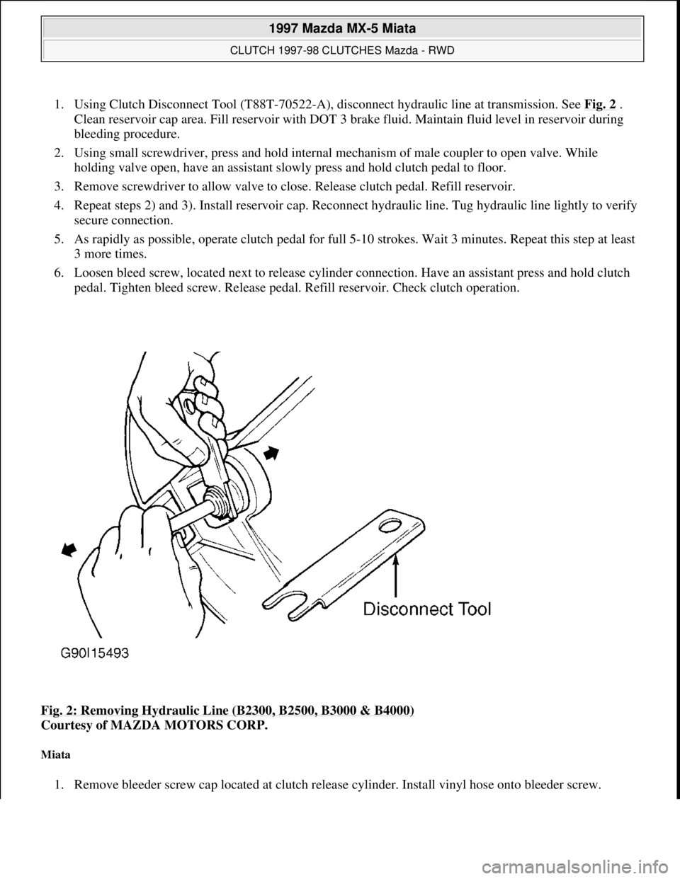
1. Using Clutch Disconnect Tool (T88T-70522-A), disconnect hydraulic line at transmission. See Fig. 2 .
Clean reservoir cap area. Fill reservoir with DOT 3 brake fluid. Maintain fluid level in reservoir during
bleeding procedure.
2. Using small screwdriver, press and hold internal mechanism of male coupler to open valve. While
holding valve open, have an assistant slowly press and hold clutch pedal to floor.
3. Remove screwdriver to allow valve to close. Release clutch pedal. Refill reservoir.
4. Repeat steps 2) and 3). Install reservoir cap. Reconnect hydraulic line. Tug hydraulic line lightly to verify
secure connection.
5. As rapidly as possible, operate clutch pedal for full 5-10 strokes. Wait 3 minutes. Repeat this step at least
3 more times.
6. Loosen bleed screw, located next to release cylinder connection. Have an assistant press and hold clutch
pedal. Tighten bleed screw. Release pedal. Refill reservoir. Check clutch operation.
Fig. 2: Removing Hydraulic Line (B2300, B2500, B3000 & B4000)
Courtesy of MAZDA MOTORS CORP.
Miata
1. Remove bleeder screw cap located at clutch release cylinder. Install vinyl hose onto bleeder screw.
1997 Mazda MX-5 Miata
CLUTCH 1997-98 CLUTCHES Mazda - RWD
Microsoft
Sunday, July 05, 2009 1:36:47 PMPage 3 © 2005 Mitchell Repair Information Company, LLC.
Page 160 of 514
Submerge other end of hose in container of brake fluid.
2. Fill reservoir with DOT 3 brake fluid. Have an assistant press and release clutch pedal several times, then
hold pedal down. With pedal pressed, loosen bleeder screw to let air and fluid escape.
3. Repeat step 2) until no more air bubbles emerge from hose. Tighten bleeder screw. Fill reservoir. Operate
clutch while inspecting for leaks. Check clutch and brake operation.
REMOVAL & INSTALLATION
CLUTCH ASSEMBLY
Removal (B2300, B2500, B3000 & B4000)
1. Disconnect negative battery cable. Shift transmission into Neutral. Remove gearshift lever. Raise and
support vehicle. Mark drive shaft flanges for installation reference. Remove drive shaft. Using Clutch
Disconnect Tool (T88T-70522-A), disconnect hydraulic line at transmission. See Fig. 2
. Plug hydraulic
line to prevent contamination. Disconnect wiring at transmission.
2. Remove starter. Remove exhaust components as necessary for clearance. On 4WD models, remove skid
plate and transfer case. On all models, secure transmission jack under transmission. Remove transmission
mount-to-crossmember nuts and bolts.
3. Remove nuts securing crossmember to frame side rails, and remove crossmember. Lower transmission
enough to gain access to transmission-to-engine block bolts. Remove transmission-to-engine block bolts.
Remove transmission.
4. If clutch parts are going to be reused, mark clutch cover and flywheel for reassembly reference. Loosen
pressure plate bolts evenly in crisscross pattern until springs are not under tension. Remove clutch cover
and clutch disc.
Inspection (B2300, B2500, B3000 & B4000)
1. Inspect disc for loose rivets, worn or defective springs, excessive wear, or oil contamination. Inspect
flywheel and clutch cover for burns, scoring, or grooves.
2. Measure flywheel and clutch cover runout. Resurface or replace flywheel and clutch cover if beyond
specification. See CLUTCH RUNOUT (MAXIMUM)
table.
3. Measure clutch disc runout. Replace disc if it is not to specification. See CLUTCH RUNOUT
(MAXIMUM) table. Inspect disc hub and input shaft splines for excessive wear. Hub must slide
smoothly on input shaft splines.
4. Inspect pilot bearing for wear. Apply inward pressure while rotating pilot bearing. If bearing sticks or has
excessive resistance, replace bearing. Check for tight fit in crankshaft. Replace as necessary. Inspect
release bearing for smooth operation, wear, damage, or looseness. Replace bearing as necessary.
CLUTCH RUNOUT (MAXIMUM)
ApplicationIn. (mm)
Disc0.028 (0.7)
Flywheel0.008 (0.20)
1997 Mazda MX-5 Miata
CLUTCH 1997-98 CLUTCHES Mazda - RWD
Microsoft
Sunday, July 05, 2009 1:36:47 PMPage 4 © 2005 Mitchell Repair Information Company, LLC.
Page 190 of 514
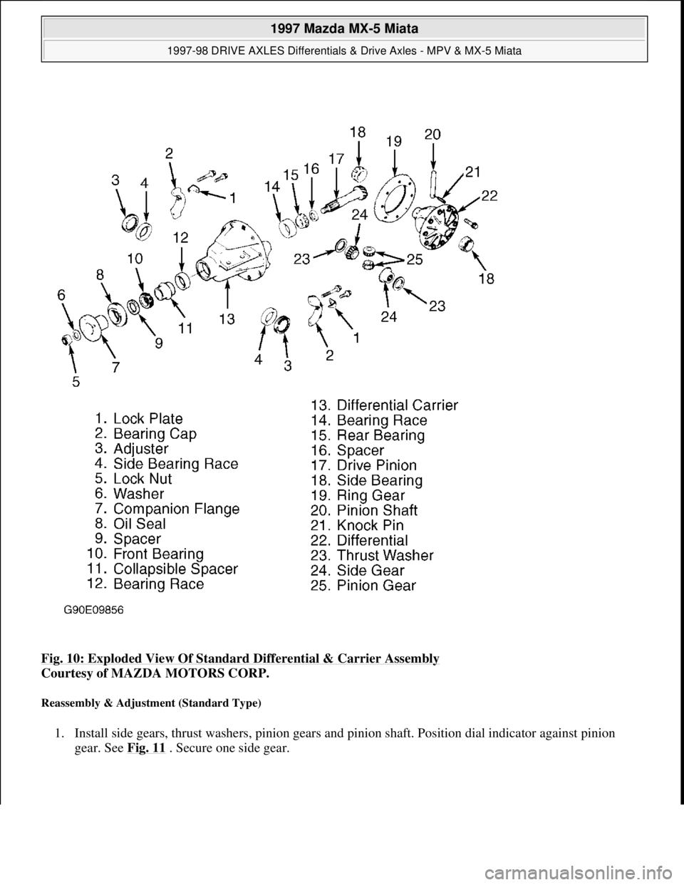
Fig. 10: Exploded View Of Standard Differential & Carrier Assembly
Courtesy of MAZDA MOTORS CORP.
Reassembly & Adjustment (Standard Type)
1. Install side gears, thrust washers, pinion gears and pinion shaft. Position dial indicator against pinion
gear. See Fig. 11 . Secure one side gear.
1997 Mazda MX-5 Miata
1997-98 DRIVE AXLES Differentials & Drive Axles - MPV & MX-5 Miata
Microsoft
Sunday, July 05, 2009 1:52:42 PMPage 16 © 2005 Mitchell Repair Information Company, LLC.
Page 191 of 514
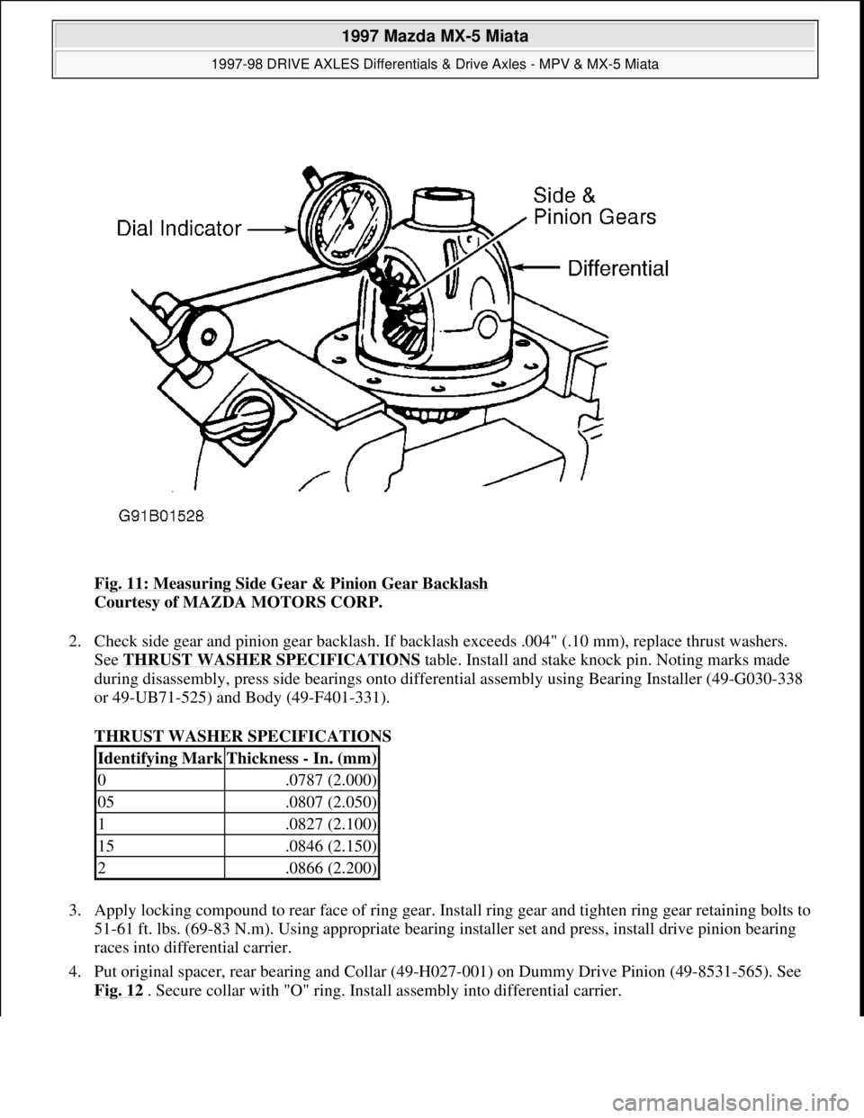
Fig. 11: Measuring Side Gear & Pinion Gear Backlash
Courtesy of MAZDA MOTORS CORP.
2. Check side gear and pinion gear backlash. If backlash exceeds .004" (.10 mm), replace thrust washers.
See THRUST WASHER SPECIFICATIONS
table. Install and stake knock pin. Noting marks made
during disassembly, press side bearings onto differential assembly using Bearing Installer (49-G030-338
or 49-UB71-525) and Body (49-F401-331).
THRUST WASHER SPECIFICATIONS
3. Apply locking compound to rear face of ring gear. Install ring gear and tighten ring gear retaining bolts to
51-61 ft. lbs. (69-83 N.m). Using appropriate bearing installer set and press, install drive pinion bearing
races into differential carrier.
4. Put original spacer, rear bearing and Collar (49-H027-001) on Dummy Drive Pinion (49-8531-565). See
Fig. 12
. Secure collar with "O" ring. Install assembly into differential carrier.
Identifying MarkThickness - In. (mm)
0.0787 (2.000)
05.0807 (2.050)
1.0827 (2.100)
15.0846 (2.150)
2.0866 (2.200)
1997 Mazda MX-5 Miata
1997-98 DRIVE AXLES Differentials & Drive Axles - MPV & MX-5 Miata
Microsoft
Sunday, July 05, 2009 1:52:42 PMPage 17 © 2005 Mitchell Repair Information Company, LLC.
Page 208 of 514
Remove rear seat cushions. Disconnect fuel pump connector. Start engine and allow to stall. After engine stalls,
attempt to restart engine to ensure no residual pressure exists. Turn ignition off and reconnect fuel pump
connector. When disconnecting fuel hoses, cover connection with shop rag to catch fuel leakage. To avoid
excessive cranking after servicing, prime fuel system before starting engine.
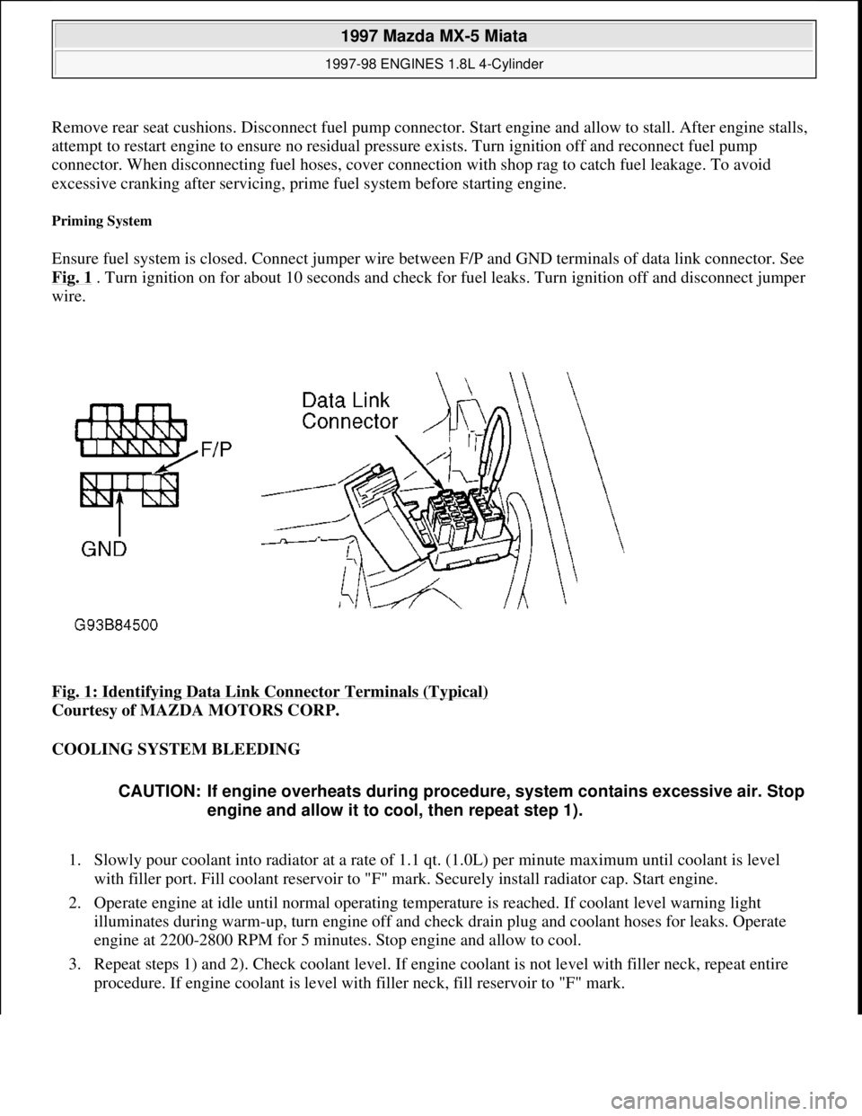
Priming System
Ensure fuel system is closed. Connect jumper wire between F/P and GND terminals of data link connector. See
Fig. 1
. Turn ignition on for about 10 seconds and check for fuel leaks. Turn ignition off and disconnect jumper
wire.
Fig. 1: Identifying Data Link Connector Terminals (Typical)
Courtesy of MAZDA MOTORS CORP.
COOLING SYSTEM BLEEDING
1. Slowly pour coolant into radiator at a rate of 1.1 qt. (1.0L) per minute maximum until coolant is level
with filler port. Fill coolant reservoir to "F" mark. Securely install radiator cap. Start engine.
2. Operate engine at idle until normal operating temperature is reached. If coolant level warning light
illuminates during warm-up, turn engine off and check drain plug and coolant hoses for leaks. Operate
engine at 2200-2800 RPM for 5 minutes. Stop engine and allow to cool.
3. Repeat steps 1) and 2). Check coolant level. If engine coolant is not level with filler neck, repeat entire
procedure. If engine coolant is level with filler neck, fill reservoir to "F" mark.
CAUTION: If engine overheats during procedure, system contains excessive air. Stop
engine and allow it to cool, then repeat step 1).
1997 Mazda MX-5 Miata
1997-98 ENGINES 1.8L 4-Cylinder
Microsoft
Sunday, July 05, 2009 1:55:15 PMPage 2 © 2005 Mitchell Repair Information Company, LLC.
Page 214 of 514
Fig. 5: Removing Engine Components (Protege)
Courtesy of MAZDA MOTORS CORP.
2. Lower vehicle. Remove air cleaner assembly. Remove battery/carrier assembly. Remove throttle cable
and air intake duct across radiator (if equipped).
3. Remove all drive belts. DO NOT disconnect power steering hoses or A/C compressor hoses. Unbolt
power steering pump and A/C compressor from engine, and wire aside.
4. Note locations and disconnect all necessary electrical connectors, ground wires, vacuum hoses, fuel
hoses, coolant hoses and control cables for engine removal.
5. Plug all fuel hoses to avoid leakage. Attach engine support bar or engine hoist to secure engine. Raise
vehicle. Disconnect exhaust manifold down pipe and exhaust brackets from engine. On A/T models,
remove shift control cable.
6. On M/T models, remove shift control linkage and extension bar. Remove clutch release cylinder and fluid
line bracket from transaxle housing, leaving fluid line connected to cylinder. Secure cylinder away from
transaxle.
7. On all models, remove transmission wiring harness connectors and speedometer cable. Remove axle shaft
nuts from hubs. Disconnect stabilizer bar from lower control arms. Separate lower ball joints and steering
tie-rod ends from steering knuckles.
8. Pry axle shafts out of transaxle. Remove and discard circlip from axle shafts. For further information on
axle shafts, see appropriate article in DRIVE AXLES.
9. Remove transaxle mount nuts from crossmember and loosen crossmember bolts. See Fig. 6
. Lower
vehicle and attach engine hoist for engine removal. Remove engine front mount and transaxle top mount
from inner fender panels. Remove transaxle crossmember. Remove engine and transaxle assembly from
top of vehicle.
10. To install, reverse removal procedure. Tighten bolts and nuts to specifications. See TORQUE
SPECIFICATIONS . Fill all fluids to correct level. Prime fuel system before attempting to start engine.
See FUEL PRESSURE RELEASE & PRIMING
. Bleed cooling system. See COOLING SYSTEM
BLEEDING.
1997 Mazda MX-5 Miata
1997-98 ENGINES 1.8L 4-Cylinder
Microsoft
Sunday, July 05, 2009 1:55:15 PMPage 8 © 2005 Mitchell Repair Information Company, LLC.
Page 227 of 514
1. Drain engine coolant. Disconnect battery cable. Position No. 1 cylinder at TDC of compression stroke.
On Protege, remove right side cover and undercover.
2. On Miata, remove air cleaner intake duct from between throttle body and air cleaner/filter assembly. On
all models, remove upper radiator hose and by-pass hoses from thermostat housing.
3. Remove drive belts and water pump pulley. Remove power steering pump with hoses attached and secure
pump away from engine (if necessary). Remove timing belt, tensioner and idler. See TIMING BELT.
4. Unbolt water inlet pipe from water pump. Water pump inlet pipe has lower radiator hose and by-pass pipe
attached to it. Remove bolts from water pump. To install, reverse removal procedure. Tighten bolt to
specification. See TORQUE SPECIFICATIONS
.
OIL PAN
Removal & Installation (Miata)
1. Disconnect negative battery cable. Drain engine oil. Remove dipstick, tube and "O" ring. Raise vehicle on
hoist. Remove engine undercover. Disconnect steering column shaft at steering rack coupling. See Fig.
14 . Remove engine mount nuts. Lift and support engine using jack.
2. Support crossmember using transmission jack and remove crossmember bolts. Slowly and carefully lower
crossmember until clearance between oil pan and steering rack is about 4 inches. Remove oil pan bolts
from engine block and transmission.
3. DO NOT damage sealant contact surfaces. Remove oil pan by prying between oil pan and transmission
support. Remove oil pan baffle by prying it from engine. See Fig. 14
. DO NOT deform oil pan baffle.
Replace oil pan baffle if deformed. Clean sealant from oil pan, bolts, engine block and both sides of oil
pan baffle.
4. To install, apply oil resistant sealant to engine block and oil pan. Install oil pan baffle and oil pan within 5
minutes of applying sealant. To complete installation, reverse removal procedure. Tighten bolts to
specification. See TORQUE SPECIFICATIONS
. Fill engine with oil to specification. See ENGINE
LUBRICATION SYSTEM under ENGINE OILING. NOTE: For further information on cooling systems, see SPECIFICATIONS & ELECTRIC
COOLING FANS article in ENGINE COOLING.
NOTE: On Miata, engine must be supported in order to remove oil pan.
1997 Mazda MX-5 Miata
1997-98 ENGINES 1.8L 4-Cylinder
Microsoft
Sunday, July 05, 2009 1:55:15 PMPage 21 © 2005 Mitchell Repair Information Company, LLC.