clock MAZDA MX-5 1997 Factory Repair Manual
[x] Cancel search | Manufacturer: MAZDA, Model Year: 1997, Model line: MX-5, Model: MAZDA MX-5 1997Pages: 514, PDF Size: 17.89 MB
Page 1 of 514
AIR BAG RESTRAINT SYSTEM
1997 ACCESSORIES/SAFETY EQUIPMENT Mazda - Air Bag Restraint System
DESCRIPTION & OPERATION
The Supplemental Restraint System (SRS), when used in conjunction with seat belt, provides increased
protection for driver and front passenger in a frontal collision. The air bag restraint system consists of AIR BAG
warning light, driver-side air bag module, passenger-side air bag module, clockspring, SAS unit, and wiring
harness. See Fig. 1
. WARNING:To avoid injury from accidental air bag deployment, read and carefully
follow all WARNINGS and SERVICE PRECAUTIONS
.
1997 Mazda MX-5 Miata
AIR BAG RESTRAINT SYSTEM 1997 ACCESSORIES/SAFETY EQUIPMENT Mazda - Air Bag Restraint System
1997 Mazda MX-5 Miata
AIR BAG RESTRAINT SYSTEM 1997 ACCESSORIES/SAFETY EQUIPMENT Mazda - Air Bag Restraint System
Microsoft
Sunday, July 05, 2009 1:40:47 PMPage 1 © 2005 Mitchell Repair Information Company, LLC.
Microsoft
Sunday, July 05, 2009 1:40:53 PMPage 1 © 2005 Mitchell Repair Information Company, LLC.
Page 3 of 514
SYSTEM OPERATION CHECK
Turn ignition on. AIR BAG warning light in instrument cluster should glow for 6 seconds and then turn off. If
AIR BAG warning light does not function as described, a failure has occurred in Supplemental Restraint
System (SRS). Repair malfunctioning SRS. See DIAGNOSIS
. Also, see SERVICE PRECAUTIONS .
SERVICE PRECAUTIONS
The following precautions should be observed when working with air bag systems:
Disable air bag before servicing any air bag system/steering column component. See DISABLING &
ACTIVATING AIR BAG SYSTEM .
Because of critical system operating requirements, DO NOT service any air bag system component or
wiring harness. Corrections are made by replacement only.
DO NOT use an ohmmeter to check resistance of air bag module, as it may cause air bag deployment.
When carrying a live (undeployed) module, ensure trim cover is pointed away from your body. This
minimizes chance of injury in event of accidental air bag deployment.
When placing a live air bag module on any surface, always face trim cover upward to reduce motion of
module if it is accidentally deployed.
SAS unit must always be installed with arrow facing the front of the vehicle.
DO NOT disconnect SAS unit until unit is firmly mounted in vehicle.
Disconnecting or removing SAS unit with ignition switch in ON position can cause accidental
deployment and serious personal injury. Before disconnecting or removing SAS unit connector or
removing SAS unit, turn ignition to LOCK position.
Air bag system clockspring MUST be aligned in neutral position, since its rotation ability is limited. DO
NOT turn steering wheel or column after removal of steering gear.
A double-lock mechanism is used on clockspring connectors. DO NOT use excessive force when
disconnecting connectors, as damage to connector may occur.
ADJUSTMENTS
CLOCKSPRING CENTERING
Turn clockspring clockwise until it stops, then turn clockspring counterclockwise 2.75 turns. Align marks on
clocksprin
g with marks on outer housing. See Fig. 2.
1997 Mazda MX-5 Miata
AIR BAG RESTRAINT SYSTEM 1997 ACCESSORIES/SAFETY EQUIPMENT Mazda - Air Bag Restraint System
Microsoft
Sunday, July 05, 2009 1:40:47 PMPage 3 © 2005 Mitchell Repair Information Company, LLC.
Page 4 of 514
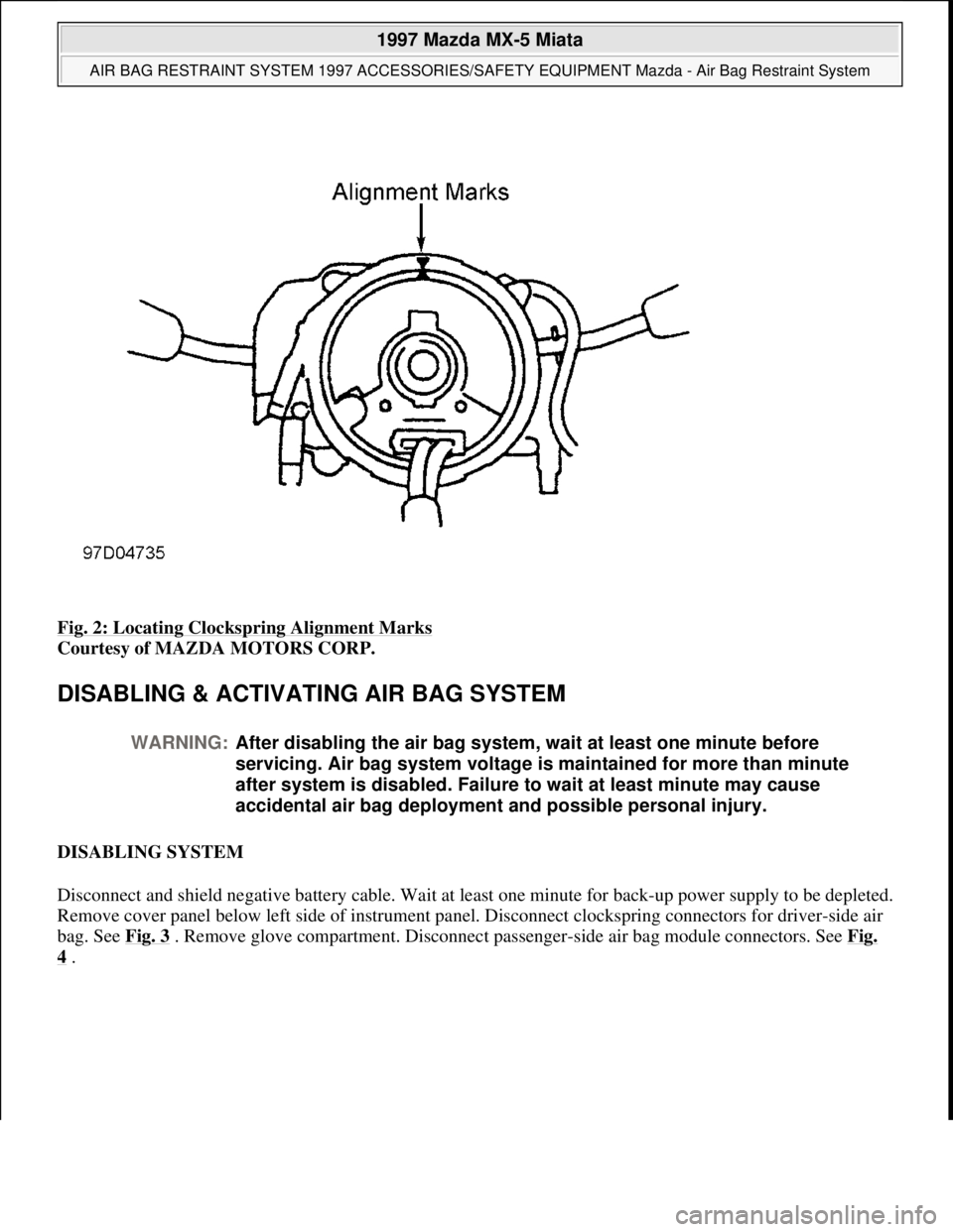
Fig. 2: Locating Clockspring Alignment Marks
Courtesy of MAZDA MOTORS CORP.
DISABLING & ACTIVATING AIR BAG SYSTEM
DISABLING SYSTEM
Disconnect and shield negative battery cable. Wait at least one minute for back-up power supply to be depleted.
Remove cover panel below left side of instrument panel. Disconnect clockspring connectors for driver-side air
bag. See Fig. 3
. Remove glove compartment. Disconnect passenger-side air bag module connectors. See Fig.
4 .
WARNING:After disabling the air bag system, wait at least one minute before
servicing. Air bag system voltage is maintained for more than minute
after system is disabled. Failure to wait at least minute may cause
accidental air bag deployment and possible personal injury.
1997 Mazda MX-5 Miata
AIR BAG RESTRAINT SYSTEM 1997 ACCESSORIES/SAFETY EQUIPMENT Mazda - Air Bag Restraint System
Microsoft
Sunday, July 05, 2009 1:40:47 PMPage 4 © 2005 Mitchell Repair Information Company, LLC.
Page 5 of 514
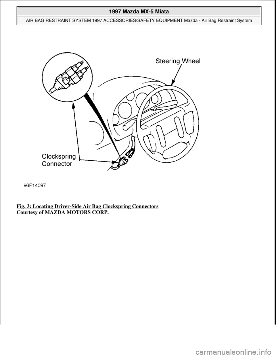
Fig. 3: Locating Driver-Side Air Bag Clockspring Connectors
Courtesy of MAZDA MOTORS CORP.
1997 Mazda MX-5 Miata
AIR BAG RESTRAINT SYSTEM 1997 ACCESSORIES/SAFETY EQUIPMENT Mazda - Air Bag Restraint System
Microsoft
Sunday, July 05, 2009 1:40:47 PMPage 5 © 2005 Mitchell Repair Information Company, LLC.
Page 6 of 514
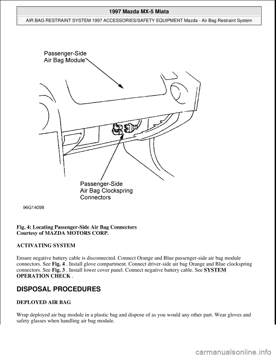
Fig. 4: Locating Passenger-Side Air Bag Connectors
Courtesy of MAZDA MOTORS CORP.
ACTIVATING SYSTEM
Ensure negative battery cable is disconnected. Connect Orange and Blue passenger-side air bag module
connectors. See Fig. 4
. Install glove compartment. Connect driver-side air bag Orange and Blue clockspring
connectors. See Fig. 3
. Install lower cover panel. Connect negative battery cable. See SYSTEM
OPERATION CHECK .
DISPOSAL PROCEDURES
DEPLOYED AIR BAG
Wrap deployed air bag module in a plastic bag and dispose of as you would any other part. Wear gloves and
safet
y glasses when handling air bag module.
1997 Mazda MX-5 Miata
AIR BAG RESTRAINT SYSTEM 1997 ACCESSORIES/SAFETY EQUIPMENT Mazda - Air Bag Restraint System
Microsoft
Sunday, July 05, 2009 1:40:47 PMPage 6 © 2005 Mitchell Repair Information Company, LLC.
Page 7 of 514
SCRAPPED VEHICLE
INSPECTING DEPLOYMENT TOOL
1. Connect Red deployment tool clip to battery positive terminal. Connect Black deployment tool clip to
battery negative terminal. Observe deployment tool lights. Green light should be on with Red light off.
2. Connect deployment tool connector "A" to connector "B". See Fig. 5
. Green light should be off with Red
light on. Press deployment tool activation switch. Green light should be on with Red light off.
3. If deployment tool lights function as described, it is safe to use deployment tool to activate air bag. If
deployment tool lights do not function as described, DO NOT use deployment tool. Replace deployment
tool with another unit and repeat procedure.
Driver-Side Air Bag
1. Before deploying air bag, inspect operating condition of Deployment Tool (49 H066 002). See
INSPECTING DEPLOYMENT TOOL
under DISPOSAL PROCEDURES. Ensure vehicle is in an
open space and away from other vehicles and people. Open doors. Open convertible top (if equipped).
Disconnect negative battery cable.
2. Remove lower center panel. Disconnect clockspring connectors from driver-side air bag. See Fig. 3
.
3. Connect deployment tool (49 H066 002) to clockspring connector. See Fig. 5
. Connect Red deployment
tool clip to battery positive terminal. Connect Black deployment tool clip to battery negative terminal.
Verify deployment tool Red light is on.
4. Ensure all persons are at least 20 feet from vehicle. Press deployment tool activation switch to deploy air
bag. Because of heat generated from air bag deployment, wait at least 15 minutes before handling
deplo
yed air bag module. NOTE: When scrapping vehicles with an undeployed air bag(s), air bag(s) must be
deployed inside vehicle.
NOTE: Deployment tool should always be inspected for proper operation before
deploying air bag.
1997 Mazda MX-5 Miata
AIR BAG RESTRAINT SYSTEM 1997 ACCESSORIES/SAFETY EQUIPMENT Mazda - Air Bag Restraint System
Microsoft
Sunday, July 05, 2009 1:40:47 PMPage 7 © 2005 Mitchell Repair Information Company, LLC.
Page 8 of 514
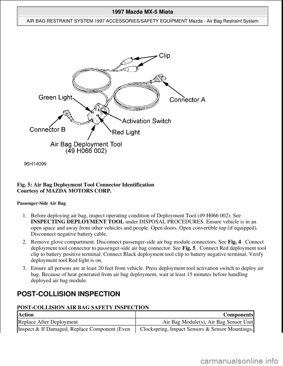
Fig. 5: Air Bag Deployment Tool Connector Identification
Courtesy of MAZDA MOTORS CORP.
Passenger-Side Air Bag
1. Before deploying air bag, inspect operating condition of Deployment Tool (49 H066 002). See
INSPECTING DEPLOYMENT TOOL
under DISPOSAL PROCEDURES. Ensure vehicle is in an
open space and away from other vehicles and people. Open doors. Open convertible top (if equipped).
Disconnect negative battery cable.
2. Remove glove compartment. Disconnect passenger-side air bag module connectors. See Fig. 4
. Connect
deployment tool connector to passenger-side air bag connector. See Fig. 5
. Connect Red deployment tool
clip to battery positive terminal. Connect Black deployment tool clip to battery negative terminal. Verify
deployment tool Red light is on.
3. Ensure all persons are at least 20 feet from vehicle. Press deployment tool activation switch to deploy air
bag. Because of heat generated from air bag deployment, wait at least 15 minutes before handling
deployed air bag module.
POST-COLLISION INSPECTION
POST-COLLISION AIR BAG SAFETY INSPECTION
ActionComponents
Replace After DeploymentAir Bag Module(s), Air Bag Sensor Unit
Inspect & If Damaged, Replace Component (Even Clockspring, Impact Sensors & Sensor Mountings,
1997 Mazda MX-5 Miata
AIR BAG RESTRAINT SYSTEM 1997 ACCESSORIES/SAFETY EQUIPMENT Mazda - Air Bag Restraint System
Microsoft
Sunday, July 05, 2009 1:40:47 PMPage 8 © 2005 Mitchell Repair Information Company, LLC.
Page 12 of 514
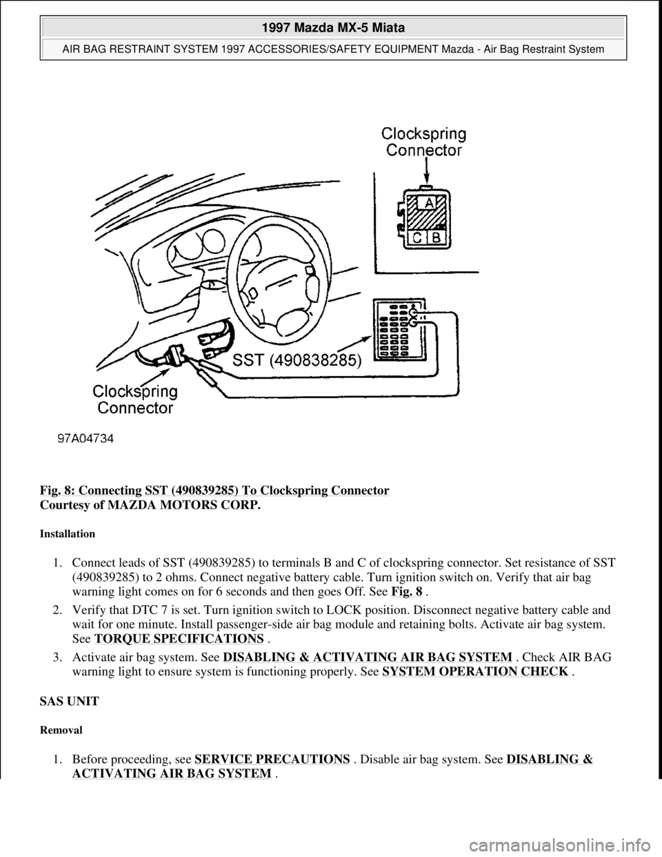
Fig. 8: Connecting SST (490839285) To Clockspring Connector
Courtesy of MAZDA MOTORS CORP.
Installation
1. Connect leads of SST (490839285) to terminals B and C of clockspring connector. Set resistance of SST
(490839285) to 2 ohms. Connect negative battery cable. Turn ignition switch on. Verify that air bag
warning light comes on for 6 seconds and then goes Off. See Fig. 8
.
2. Verify that DTC 7 is set. Turn ignition switch to LOCK position. Disconnect negative battery cable and
wait for one minute. Install passenger-side air bag module and retaining bolts. Activate air bag system.
See TORQUE SPECIFICATIONS
.
3. Activate air bag system. See DISABLING & ACTIVATING AIR BAG SYSTEM
. Check AIR BAG
warning light to ensure system is functioning properly. See SYSTEM OPERATION CHECK
.
SAS UNIT
Removal
1. Before proceeding, see SERVICE PRECAUTIONS . Disable air bag system. See DISABLING &
ACTIVATING AIR BAG SYSTEM.
1997 Mazda MX-5 Miata
AIR BAG RESTRAINT SYSTEM 1997 ACCESSORIES/SAFETY EQUIPMENT Mazda - Air Bag Restraint System
Microsoft
Sunday, July 05, 2009 1:40:47 PMPage 12 © 2005 Mitchell Repair Information Company, LLC.
Page 13 of 514
2. Drain cooling system. Remove dashboard. Remove heater unit. SAS unit connectors. Remove 4 SAS unit
mounting bracket nuts. Remove 2 SAS unit retaining screws. Remove SAS unit. See Fig. 9
.
Installation
To install, reverse removal procedure. Position SAS unit and bracket with arrow toward front of vehicle.
Tighten fasteners to specification. See TORQUE SPECIFICATIONS
. After SAS unit is installed, activate air
bag system. See DISABLING & ACTIVATING AIR BAG SYSTEM
. Check AIR BAG warning light to
ensure system is functioning properly. See SYSTEM OPERATION CHECK
.
CLOCKSPRING
Removal
1. Set front wheels in straight-ahead position. Before proceeding, see SERVICE PRECAUTIONS .
Disable air bag system. See DISABLING & ACTIVATING AIR BAG SYSTEM
.
2. Remove driver-side air bag module. See DRIVER
-SIDE AIR BAG MODULE . Remove steering wheel
nut. Using a puller, remove steering wheel. Remove steering column covers. Remove clockspring screws.
Remove clockspring and combination switch as an assembly.
Installation
1. To install, reverse removal procedure. Tighten steering wheel nut to specification. See TORQUE
SPECIFICATIONS .
2. After installation, activate air bag system. See DISABLING & ACTIVATING AIR BAG SYSTEM
.
Check AIR BAG warning light to ensure system is functioning properly. See SYSTEM OPERATION
CHECK .
SAS UNIT
Removal
1. Before proceeding, see SERVICE PRECAUTIONS . Disable air bag system. See DISABLING &
ACTIVATING AIR BAG SYSTEM .
2. SAS unit is located under center of dashboard. See Fig. 1
. Remove dashboard. Remove heater assembly.
Disconnect SAS unit connectors. Remove 4 SAS unit mounting bracket nuts. Remove 2 SAS unit
retainin
g screws. Remove SAS unit. See Fig. 9. NOTE: Clockspring is part of combination switch. When replacing clockspring, replace
the clockspring and combination switch as an assembly.
1997 Mazda MX-5 Miata
AIR BAG RESTRAINT SYSTEM 1997 ACCESSORIES/SAFETY EQUIPMENT Mazda - Air Bag Restraint System
Microsoft
Sunday, July 05, 2009 1:40:47 PMPage 13 © 2005 Mitchell Repair Information Company, LLC.
Page 18 of 514
Remove driver-side air bag module. See DRIVER-SIDE AIR BAG MODULE under REMOVAL &
INSTALLATION.
2. Inspect clockspring connectors for damage. If connectors are okay, go to next step. If connectors are
damaged, replace clockspring. Perform SYSTEM OPERATION CHECK
.
3. Connect Special Service Tool (49 0839 285) to terminal No. 3B and terminal No. 3C of clockspring. Set
SST resistance to 2 ohms. Connect clockspring connector. Connect negative battery cable. Turn ignition
switch to ON position and cheek for codes. If CODE 6 is displayed, go to next step. If CODE 6 is not
present, replace driver-side air bag module. Perform SYSTEM OPERATION CHECK
.
4. Turn ignition switch to LOCK position. Disconnect negative battery cable and wait for 1 minute.
Disconnect clockspring connector and inspect. If pins are ok go next step. If pins are damaged, replace
wiring harness from clockspring to SAS unit.
5. Connect Special Service Tool (49 0839 285) to terminal No. A and terminal No. B of clockspring
connector. Set SST resistance to 2 ohms. Connect clockspring connector and connect negative battery
cable. Turn ignition switch to ON position and cheek for codes. If CODE 6 is displayed, go to next step.
If CODE 6 is not present, replace clockspring. See CLOCKSPRING
under REMOVAL &
INSTALLATION. Perform SYSTEM OPERATION CHECK
.
6. Turn ignition switch to LOCK position. Disconnect negative battery cable. Wait for 1 minute. Remove
dashboard and heater unit. Disconnect SAS unit connector.
7. Check wiring harness between terminal No. O of SAS unit connector and between terminal No. A of
clockspring connector. Also check between terminal No. M of SAS unit connector and terminal No. B of
clockspring connector. Check for short to ground, short to power or open circuit. If wiring is OK, replace
SAS unit. See SAS UNIT
under REMOVAL & INSTALLATION.If wiring is not OK, replace wiring
harness from clockspring to SAS unit. Perform SYSTEM OPERATION CHECK
.
DTC 7 - PASSENGER-SIDE AIR BAG MODULE
1. Disable air bag system. See DISABLING & ACTIVATING AIR BAG SYSTEM
. Inspect passenger-
side air bag module connectors for damage. If connectors are okay, go to next step. If connectors are
damaged, replace wiring harness from passenger-side air bag module to SAS unit. Perform SYSTEM
OPERATION CHECK .
2. Connect Special Service Tool (49 0839 285) to terminal No A and terminal No. B of passenger-side air
bag module connector. Set Special Service Tool resistance to 2 ohms. Connect clockspring connector.
Connect negative battery cable. Turn ignition switch to ON position and check for codes. If DTC 7 is
displayed, go to next step. If CODE 7 is not present replace passenger-side air bag module. See
PASSENGER
-SIDE AIR BAG MODULE under REMOVAL & INSTALLATION. Perform SYSTEM
OPERATION CHECK .
3. Turn ignition switch to LOCK position. Disconnect negative battery cable and wait 1 minute. Disconnect
clocksprin
g connector. Remove dashboard and heater unit. NOTE: For connector terminal identification, see WIRING DIAGRAM
.
NOTE: When resistance is detected between terminals l-K of SAS unit is NOT 2 ohms
and/or there is no continuity between terminal No. E of SAS unit and ground,
DTC 7 will set
1997 Mazda MX-5 Miata
AIR BAG RESTRAINT SYSTEM 1997 ACCESSORIES/SAFETY EQUIPMENT Mazda - Air Bag Restraint System
Microsoft
Sunday, July 05, 2009 1:40:48 PMPage 18 © 2005 Mitchell Repair Information Company, LLC.